

patent · US4331129A
Solar energy for LNG vaporization
25 May 1982
Text
Page 1bibliographic recordscan →
United States Patent (19) 11 4,331,129 Hong et al. 45 May 25, 1982 (54) SOLAR ENERGY FOR LNGWAPORIZATION 3,867,818 2/1975 Tornay .................................... 62/52 3,892,103 7/1975 Antonelli................................ 62/58 Inventors: Charles C. Hong, Columbus; David E. 3,978,663 9/1976 Mandrin et al. 60/39.67 Price, Plain City; William F. Morse, 4,003,363 1/1977 Grossman ...... ... 126/450 Columbus, all of Ohio 4,004,380 l/1977 Kwake ...................................... 52/2 4,033,326 7/1977 Leitner ....... ... 26/415 73 Assignee: Columbia Gas System Service 4,037,652 7/1977 Brugger . 126/435 Corporation, Columbus, Ohio 4,057,048 11/1977 Maine ..... ... 126/440 4,063,419 12/1977 Garrett ... ... 126/435 21 Appl. No.: 55,008 4,143,642 3/1979 Beaulieu, ... 126/435 22 Filed: Jul. 5, 1979 4,253,446 3/1981 Muller ................................. 126/435 Int. Cl. ................................................. F24J 3/02 Primary Examiner-Carroll B. Dority, Jr. 52 U.S.C. .................................... 126/427; 126/435; Attorney, Agent, or Firm-Millard & Cox 126/900; 62/52 ABSTRACT Field of Search ............... 126/452, 900, 435, 420, Disclosed is an apparatus for vaporizing a normally 126/427, 432; 62/52, 53; 237/80, 81 gaseous fluid which is in liquefied state which apparatus References Cited employs solar energy for heating a second fluid which
passed into heat exchange relationship with said lique 1,588,699 6/1926 Brooks .................................. 122/32 fied gaseous fluid for its vaporization. The preferred
liquefied gaseous fluid is liquefied natural gas (LNG) 3,452,548 7/1969 Pitaro ...................................... 62/53 and the second fluid preferably is water which option 3,720,057 3/1973 Arenson ... ... 60/39.02 ally contains an anti-freeze additive for prevention of 3,724,229 4/1973 Selber ..................................... 62/52 freezing of the water during the operation. 3,726,085 4/1973 Arenson ....... ... 60/36 3,726, 101 4/1973 Arenson .................................. 62/52 4 Claims, 7 Drawing Figures
solar
HEATER
CONVENTIONAL
HEATER
Drawings
Page 2drawing sheetscan →
Page 3drawing sheetscan →
Page 4drawing sheetscan →
Page 5drawing sheetscan →
Page 6drawing sheetscan →
Page 7scan →
fluid into heat exchange relationship with said liquefied
SOLAR ENERGY FOR LNG VAPORIZATION gaseous fluid for vaporizing the same. Accordingly, advantages of the present invention
BACKGROUND OF THE INVENTION include the especially efficient utilization of solar en ergy to at least augment, if not totally replace, conven
The present invention relates to the regasification or 5 tional vaporization of normally gaseous fluids in liquefied gases, such fuel combustion heaters for vaporizing liquefied as LNG. Another advantage is an especially state and more particularly to the use of solar energy for efficient solar water heater which can absorb heat from such vaporization.
Natural gas, for example, often is available in areas 10 peratures prevail,even the atmosphere when freezing ambient (air) tem remote from where it ultimately will be used. Often, These and other advantagesas will as well absorb heat from the sun.
be readily apparent to shipment of such natural gas involves marine transpor those skilled in the art from the disclosure contained tation which makes it desirable to bulk transfer the herein.
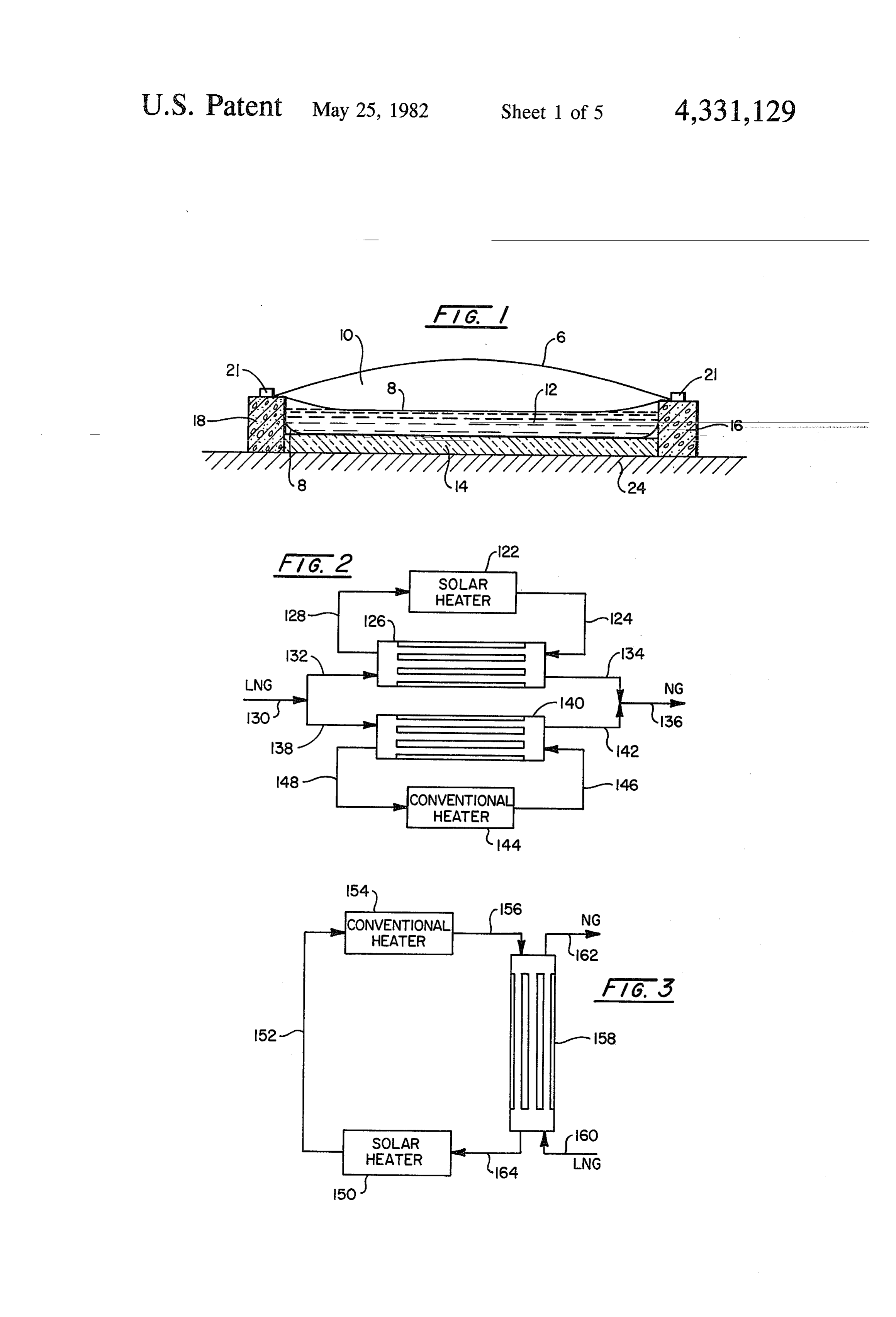
natural gas by liquefying the natural gas so as to greatly reduce its volume for transportation at essentially atmo 15 BRIEF DESCRIPTION OF THE DRAWINGS spheric pressure. Under these conditions, the liquefied FIG. 1 shows a shallow solar pond module in cross natural gas (hereinafter referred to as LNG) is at a sectional elevation.
temperature of approximately - 162 C., though FIG. 2 shows a schematic flow diagram of a solar heavier hydrocarbons (such as, for example, ethane, heater and heat exchanger therefor operating in parallel propane, butane, and the like) often vary the boiling with a conventional heater and heat exchanger therefor point range of the LNG to between about -133 and for the vaporization of LNG.
- 168° C. Heretofore, a wide variety of heat transfer FIG. 3 shows a schematic flow diagram of a solar fluids have been proposed for the regasification or va heater and conventional heater operating in series for porization of LNG. Such heat transfer fluids include air the vaporization of LNG.
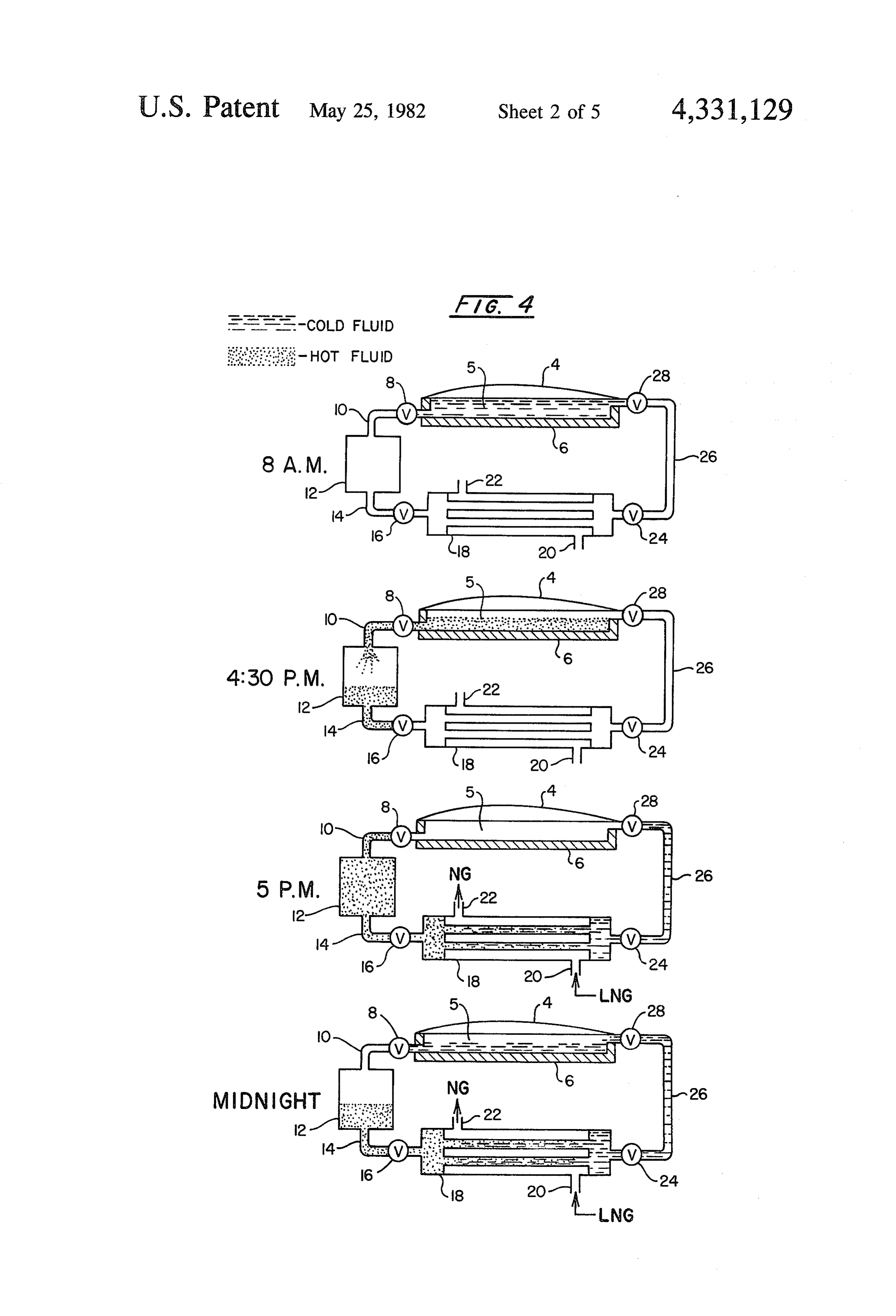
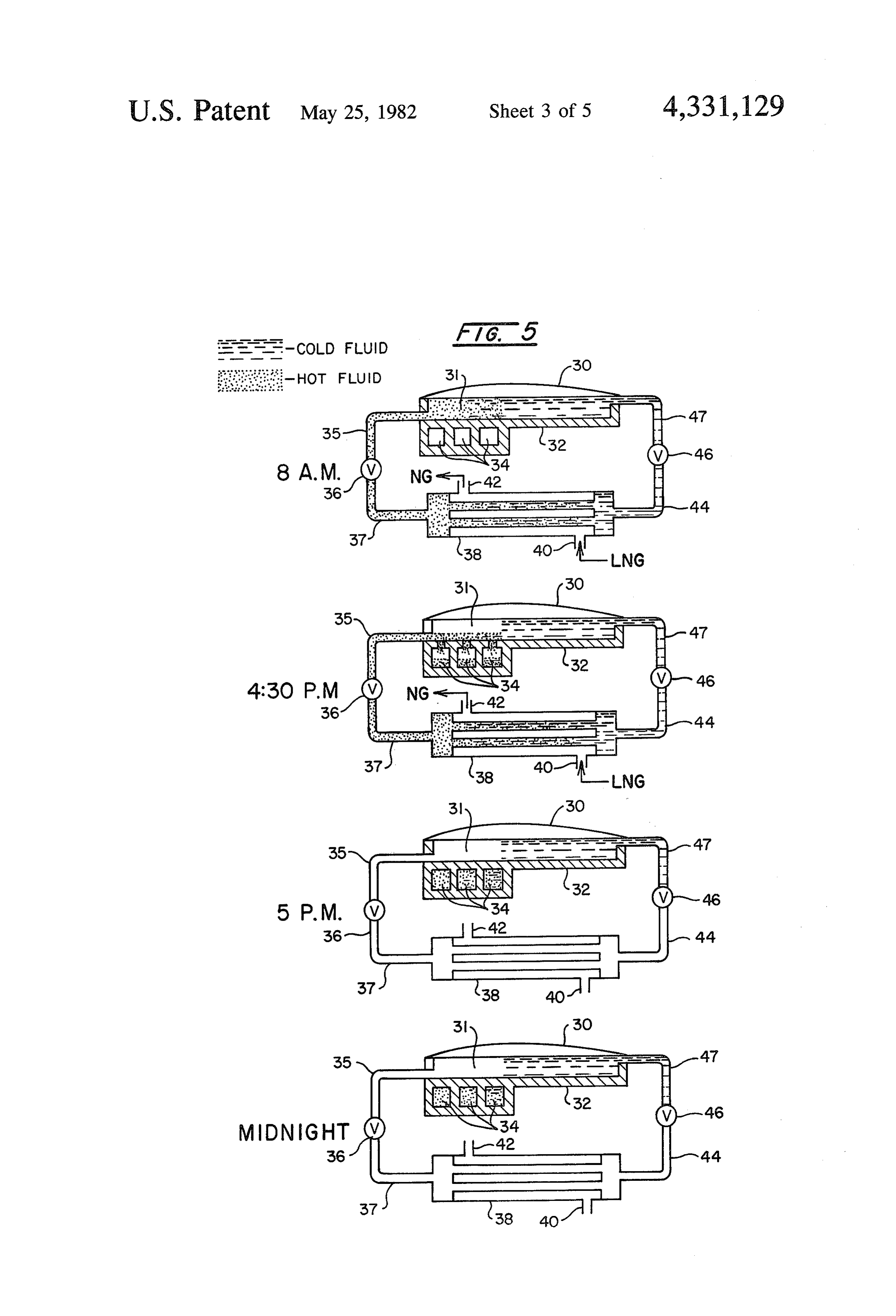
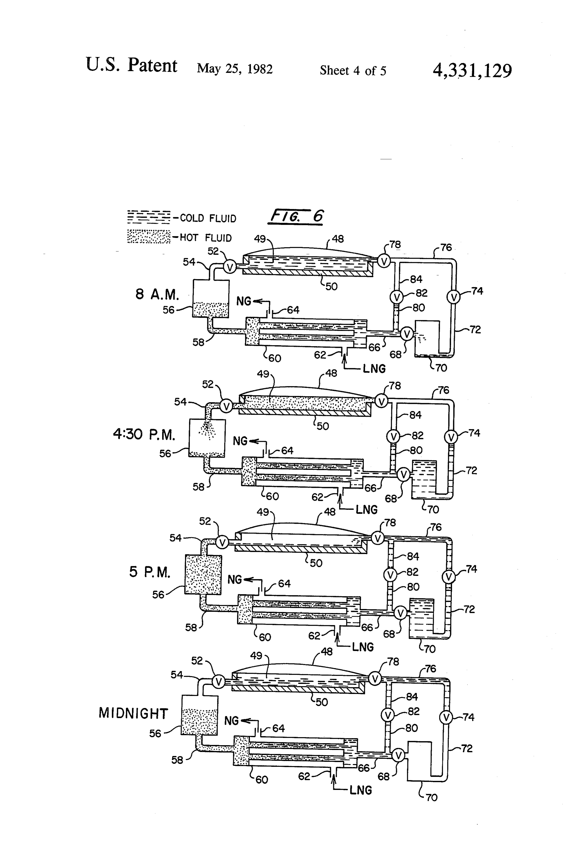
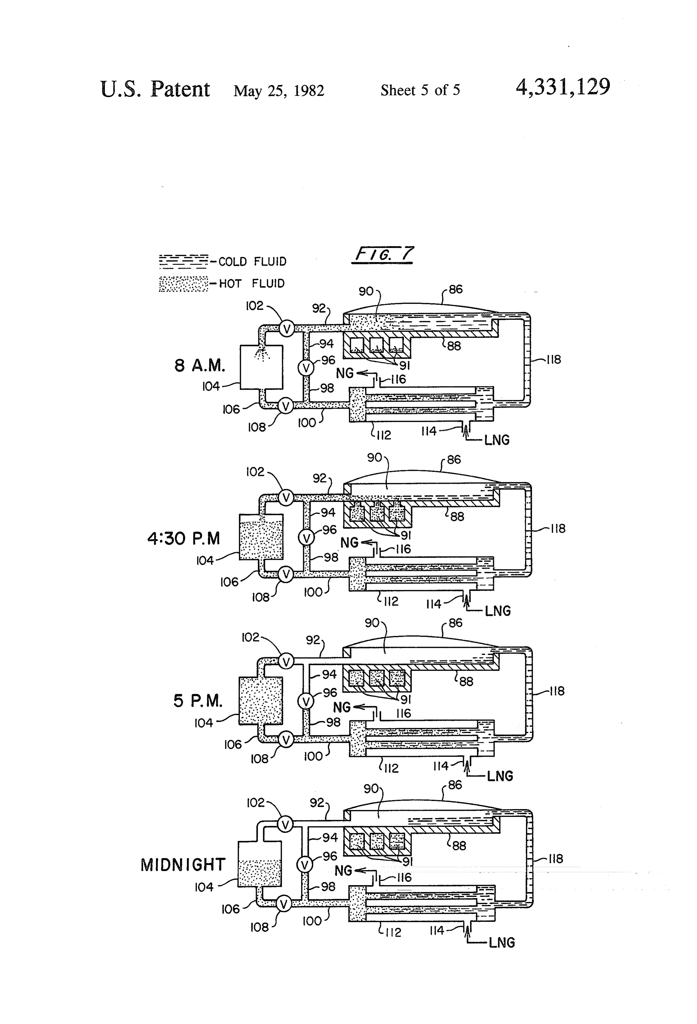
(U.S. Pat. No. 3,978,663), ambient water (U.S. Pat. Nos. 25 FIGS. 4–7 show schematic flow diagrams of LNG 3,726, 101: 3,726,085; and 3,720,057), distillate from hy vaporization installations using solar energy for the drocarbon distillation columns (U.S. Pat. No. vaporization. They will be described in detail later in 3,452,548), sea water often in conjunction with a desali connection with several design operational modes for nization process (U.S. Pat. Nos. 3,724,229; 3,892,102; practice of the present invention.
and 3,892,103), and like fluids. It even has been pro 30 DETAILED DESCRIPTION OF THE posed to vaporize liquid chlorine with ambient water DRAWINGS
In all of the foregoing prior art proposals, the heat The solar heater of FIG. 1 is a “shallow solar pond' transfer fluid can be at ambient temperature, be heated 35 module (hereinafter SSP module). The module is fitted by conventional fuel fired heaters, be heated by turbine can with cover 6 which is transparent or translucent and exhaust gas and the like. However, the application of or can be of inflatable material such as plastic or the like, solar energy for the regasification of normally gaseous the like.beCover of rigid material such as glass, fiberglass, or fluids in liquefied state has not been advocated in the erwise treated to6 can be coated on its underside or oth art, nor has an efficient and economic solar energy 40 cover 6 into the heater butsolar permit energy to pass through prevent escape of reflected system for such regasification been proposed. energy. Cover 6 is fitted over water sheath 8 to define BROAD STATEMENT OF THE INVENTION plenum 10 which can be a dead air space or pressurized One aspect of the invention is an improvement in loss air or other gas space for minimizing convective heat process wherein solar heated water is passed into a heat 45 the airfrom the solar heater. In colder climates especially exchange relationship with the medium which is at a desiccant, in plenum 10 suitably has been dried (e.g. with a lower temperature than the temperature of said solar antifreeze additive) though the air optionally may contain an heated water, the water in said process being exposed to therein. Water sheathto8preventretains freezing of water vapor the water in pond 12 and a condition adequate for freezing at least a portion of is transparent or translucent for permitting said water during said process. Such improvement com 50 to pass through it and be absorbed by pondsolar energy prises admixing with said water a sufficient proportion sheath 8 can be of similar construction as cover 6.Water
The of an additive which prevents said freezing of said wa lower layer of water sheath 8 lying on insulation 14 is a ter. Another aspect of the invention is a process for black body for absorbing heat to heat pond 12. A paint, vaporizing a normally gaseous fluid which is in lique fied state which comprises passing a solar heated second 55 coating, or manufactured black color for the lower layer of water sheath 8 can be used as is necessary, fluid into heat exchange relationship with said liquefied desirable, or convenient. The interior of SSP module is gaseous fluid for vaporizing same. Yet another aspect of retained by concrete piers 16 and 18 which in FIG. 1 the invention is an improvement in a process for vapor have anchors 21 affixed thereto for securing cover 6 and izing a normally gaseous fluid which is in liquefied state water sheath 8. Insulation 14 prevents undesirable heat wherein a second fluid is fed to a fuel combustion heater 60 loss to ground 24.
and said heated second fluid passed into heat exchange A typical SSP module will be about 5.5 by 71.5 me relationship with said liquefied gaseous fluid for vapor ters and preferably constructed of weatherable polyvi izing the same. This improvement comprises preheating nyl chloride or other plastic. The depth of water in said second fluid fed to said fuel combustion heater in a pond 12 normally will range from about 5 centimeters Solar heater. A still further aspect of the invention is a 65 to 30 centimeters for efficiency of heating pond 12. process for vaporizing a normally gaseous fluid which is Multiple modules can be laid together using piers 16 and in liquefied state which comprises passing a fuel com 18 as common interior walls and/or laid end to end. The bustion heated second fluid and a solar heated third modules can be interconnected in a variety of parallel, 8 series, and combination of parallel and series arrange changer 140. Typical operating temperatures for such a ments depending upon the heat demand required of the scheme include the solar heater heating water to about heated water. For preventing any freezing of the water 63' C. for vaporizing LNG entering the system at about in pond 12 due to low ambient temperatures and/or - 162 C. Natural gas withdrawn from the heat ex heat transfer to cryogenic fluids, for example, a suitable changers normally will be about 4 C. in temperature. additive will be admixed with the water in pond 12 such With an anti-freeze additive added to the water for the as, for example, an anti-freeze such as an alcohol, gly solar collector (solar heater 122), the cold water solu col, glycol ether, salt, ammonia and the like. Further, tion withdrawn from the heat exchangers can be in pond 12 can contain purely a hydrocarbon or hydrocar temperature as low as about - 40 C. Further, the hot bon mixture or can be a gaseous fluid such as air or the 10 water from either the solar collector or the conven like. Conventional piping, pumps, headers, feeders, and tional heater can be passed into heat exchange relation the like are not shown in FIG. 1 but are to be provided ship (heat exchangers not shown) for heating an inter in conventional fashion where necessary, desirable, or mediate heat transfer fluid such as propane or the like convenient. Further, it must be recognized that a vari and such heated intermediate fluid passed into heat ety of other construction designs can be conceived for 15 exchange relationship with the LNG for its vaporiza the SSP module and such will satisfactorily serve to tion. The parallel flow process depicted in FIG. 2 is provide heat transfer to normally gaseous fluids in liq believed to be a good design for installing a solar collec uefied state for their regasification or vaporization. tion system at an existing LNG plant which employs The inlet temperature of the water forming pond 12 conventional heating means for the vaporization of can range from as low as -40 C. and lower when an 20 LNG.
anti-freeze additive is admixed with the water to as high Referring to FIG. 3, solar heater 150 heats water or as 16-38 C. or higher depending upon prior conditions other heat transfer fluids noted above. The heated water of exposure to the water, ambient temperature to which is withdrawn from solar heater 150 through line 152 and the SSP module is exposed, and heat demand required passed into conventional heater 154. Thus, the solar of the heated water withdrawn from the SSP module. 25 heater is used as a "preheater' for preheating water or Those skilled in the art will appreciate the various com other heat transfer fluid for use in a conventional heat binations of factors which will be accounted for in de ing system. The conventional heating system can be a signing a suitable SSP module and such is within the conventionally fired burner, waste heat from gas tur skill of those in the art. bines, or the like. The finally-heated water is withdrawn Referring to FIG. 2, solar heater 122 can be used to 30 from a conventional heater 154 through line 156 and heat any suitable heating fluid, though such heater pref passed into heat exchanger 158. LNG is passed into heat erably is used to heat water for the vaporization of exchanger 158 through line 160 and vaporized natural LNG. The hot water from solar heater 122 is passed gas is withdrawn from heat exchanger 158 through line through line 124 into heat exchanger 126 from which 162. Spent cold water from heat exchanger 158 is recy spent cold water is returned to solar heater 122 through 35 cled to solar heater 150 through line 164. line 128. LNG enters the system through line 130 and The heat required to vaporize the LNG in the series can be split into two flow paths. Line 132 conveys the process depicted in FIG. 3 is the heat from the solar LNG into heat exchanger 126 where it is vaporized to collector plus the heat from the conventional heater. form natural gas which is withdrawn from heat ex With maximum solar heat collection, the heat input changer 126 through line 134 and then passed into line 40 from the conventional heater can be nominal or none. 136 for further processing and/or distribution into exist With little or no solar heat collection available, the ing natural gas lines. conventional heater can provide up to 100 percent of Conventional heater 144 can utilize gas burners, coal the heat required to vaporize the LNG. An intermedi burners, turbine exhaust gas, or like conventional means ate heat transfer fluid can be utilized in the series flow for heating water or other heat transfer fluid. The pref. 45 process shown in FIG. 3 in conventional fashion, such erable fluid for such conventional heater is water which as described above. Temperatures for all flows in this is withdrawn from heater 144 through line 146 and series flow system can be the same as the temperatures passed into heat exchanger 140. Spent cold water is given in connection with the description of FIG. 2 withdrawn from heat exchanger 140 and recycled to above. It must be recognized that for providing heat heater 144 through line 148. Alternatively, heat ex 50 transfer to other fluids, different temperatures may be changer 140 and heater 144 can be a single integrated required. Also, different temperatures may be required unit wherein the water is internally cycled. The second in the vaporization of LNG, and those temperatures flow path for the LNG is through line 138 into heat given herein are merely typical operating temperatures exchanger 140 where it is vaporized to natural gas. Such under which conventional LNG regasification plants natural gas is withdrawn from heat exchanger 140 55 have been operated.
through line 142 and passed into line 136 as described DETAILED DESCRIPTION OF THE above.
With good solar heat collection, most of the LNG INVENTION will pass through line 132 into heat exchanger 126 for its A variety of factors, design features, and operational vaporization. When insufficient solar energy is avail 60 modes ultimately will determine the details of the SSP able, the LNG can be routed through line 138 into heat module, number of modules to be established, the inter exchanger 140 for its vaporization. Suitably, a heat connection of multiple SSP modules to various surge sensor can be installed in line 124 or in solar heater 122 tanks, heat exchangers, and the like which are designed to sense the temperature of the water in order to deter in conjunction with the SSP module. Factors include mine the proportion of LNG which can be passed into 65 geographic location and climate of the SSP installation, heat exchanger 126 for its vaporization. Thus, when the season of operation of the SSP module, particular lique water in solar heater 122 drops in temperature, more fied fluid to be vaporized (for example, LNG, liquid LNG will be diverted through line 138 into heat ex oxygen, liquid nitrogen, liquid chlorine, or the like), and 9 like factors. Design features of the SSP module and appurtenant installations include intergration of con ventional fuel-fired heaters with the solar heaters, par ticular construction of the SSP module, number of mod ules established (perhaps limited by open land availabil ity though the modules may be floated on water if de sired), type of pond solution used in the SSP module, solar collection efficiency of the SSP module estab lished (frost and dew formation on and in the SSP mod ule, for example, may significantly affect the efficiency 10 of the SSP module), and like design features. The vari ous operational modes are virtually limitless and several commercially viable operational modes will be de scribed in connection with FIGS. 4–7 later herein. Underlying the above are the economics in establish 15 ing large scale solar heater installations, operational costs, and expected useful life of such installations. Still, use of solar energy has many non-economic benefits such as, for example, conservation of fossil and other depletible fuels. The description of the invention which 20 follows addresses some of the foregoing variables, but it must be remembered that custom designing of commer cial solar heater systems and their integration into exist ing or new commercial facilities probably is wise. Those skilled in the art will appreciate fully how to practice 25 the invention from the description herein and also the pertinent variables to be factored into the proper design of a complete solar system.
The invention will be particularly described in detail in connection with the vaporization or regasification of 30 LNG, though this is not a limitation on the present invention. Also, water (or an aqueous solution) is the preferred fluid for solar heating and the description herein will be with respect to water, though this is not a limitation of the invention. The solar heater modules 35 can vary from a few in number to virtually thousands of them covering up to several hundred acres of ground, depending upon the energy requirements of such solar heater system. LNG usually is at a temperature of about - 162 C. though this temperature can vary signifi cantly as noted above. Preferably, the LNG is heated to about 4 C. or thereabouts to convert it to natural gas for further processing for eventual distribution into existing gas lines. Typical commercial LNG vaporiza tion installations can produce up to 28 million standard 45 cubic meters (SCM) of vaporized natural gas daily so that energy requirements for such vaporization process can amount to billions of gram-calories per year. For SSP modules, solar energy collection efficiency increases with decreasing average pond temperature. 50 The average pond temperature (temperature of the water or other liquid fluid to be heated in the solar heater) can be lowered by increasing the depth of the water, for example. Use of an organic pond solution (for example, an alcohol, glycol, hydrocarbon, or the like) 55 permits very low inlet pond temperatures for increasing the solar energy collection efficiency of the solar heater. For solar water heaters, the addition of an anti freeze additive to the water also permits very low inlet temperatures of the water solution to be practiced (for 60 example, as low as -40° C. and lower) and, thereby, improve the solar collection efficiency of the solar water heater. Higher solar energy collection efficien cies can translate into relatively lower final solution temperatures for relatively larger throughput volumes 65 of solution or can translate into relatively higher final solution temperatures for relatively smaller throughput volumes of solution, depending upon the capacity of the solar, heater and volumetric flow rate of solution through the heater. Volumetric flow rates of the solu tion in the present invention generally are adjusted and maintained to achieve the former result. The outlet temperature of the solution from the solar heater, in turn, is an important factor in determining heat ex changer size when the solar heated solution is to be passed into heat exchange relationship with another fluid. Usually, minimum area of the heat exchanger is an important design variable for minimizing costs of the heat exchanger,
The foregoing can be illustrated by studying the ef fects of the pond depth and average solution tempera ture for a model SSP operating in a locale at which the total solar flux is known. For purposes of this illustra tion, the chosen sight was the Washington, D.C. area for which SOLMET (Solar Radiation-Surface Meteo rological Observations) information is available from the United States Department of Commerce, National Oceanic and Atmospheric Administration, Environ mental Data Service. The SOLMET information pro vides the daily total solar flux for the Washington-Sterl ing, D.C. area (as well as other locales) as compiled by the National Weather Service. For purposes of this illustration, the 1972 solar flux information was used with the “best day' solar radiation being 697 gram-calo ries per square centimeter per day as recorded for June 22, 1972. This location strictly is for purposes of illustra tion of the invention and in no way is a limitation of the invention. The solar collection efficiency for a model SSP module was determined from an empirical equa tion developed by Dickinson et al for Lawrence Liver more Laboratory and can be found in preprint UCRL 78288, revision 1 (June 17, 1976), for presentation at the International Solar Energy Society, Solar Energy Con ference '76, Winnipeg, Manitoba, Canada, Aug. 15-20, 1976. The empirical equation is based upon the Hottel Whillier-Bliss model given at page 6 as equation 2 in the cited preprint. The empirical equation developed by Dickinson et al is found on page 12, FIG. 4 of the pre print and can be expressed as follows:
Ni=collection efficiency
AT= water temperature-ambient (air) temperature
I=Total solar flux incident on SSP (BTU/Square
The pond depth and average solution temperature are independent variables in the empirical equation and determine the final solution temperature and collection efficiency of the SSP module. The collection efficiency is defined as the net energy collected divided by the total radiation or total flux incident upon the SSP mod ule. For comparative purposes, the SSP is compared to a representative commercial gas-fired heat exchange system designed for LNG vaporization wherein natural gas fired heaters are used to heat water which is passed through a heat exchanger to vaporize the LNG. The LNG is assumed to enter into the heat exchangers at -162C. and leave in vaporized form at 4°C. using hot water heated by the gas firing heaters to 42° C. The relative heat exchanger size required for the solar sys tem-compared to the size required for the conventional 10 gas heating system is calculated from the "log mean given area on the best day of the year. Such a system temperature drop' (LMTD) for each heat exchange would supply all of the energy on the best day for va system. The LMTD is used in design of heat exchangers porizing the LNG and would be the most cost effective and can be calculated from the entrance and exit tem because it would require a minimum solar collector area peratures of fluids passing through the heat exchanger. per unit energy utilized. LNG would be vaporized with The LMTD equation can be found in the Chemical such a designed system when sufficient energy is pro Engineer's Handbook, Fifth Edition, R. H. Perry and C. vided from the system, and would be supplemented H. Chilton, Section 10, page 10, equation 10–27, with natural gas or other conventional fuel heaters McGraw-Hill Book Company, New York, New York when insufficient energy from the solar system is avail (1973), the disclosure of which is expressly incorpo O able.
rated herein by reference. For the SSP module operat Several operating schemes or modes of the solar ing with entry solution temperatures of less than 0°C., heater system based on the foregoing design are possi it was assumed that methanol (45% by weight) was ble. Such a solar system could be operated on a batch added to the water in order to prevent freezing of the basis or continuously, as well as modified versions of water. The following table displays the operation pa 15 both such schemes. Certainly, an almost limitless num rameters and results that would be obtained for such a ber of operating modes can be conceived for practice of model SSP module. the invention. In order to illustrate some of the various
Table i
Relative
Pond Heat
Depth Solution Temp. (C) . Collection Efficiency (%) Log Mean Exchanger (cm) Minimum Maximum Day Night Total Temp. Drop (C.) Size % Methanol 5.08 16 63 34 O 34 107 0.91 O 4. 62 39 3 42 102 0.96 O - 40 62 39 18 57 86 1.14 45 10.16 24 55 45 O 45 104 0.94 O 16 52 53 O 53 98 0.99 O 4 48 61 3 64 92 107 O - 40 48 74 24 97 76 1.28 45 20.32 16 38 66 O 66 87 1.13 O 4 32 78 4. 82 77 1.27 O - 40 21 108 27 135 53 1.85 45 30.48 16 32 72 O 72 81 1.21 0 4. 24 84 4. 88 69 1.42 O - 40 6 124 29 153 26 3.83 45
Several valuable results are seen from the foregoing 35
Table. First, it should be noted that the solar energy modes under which the invention can be practiced, four collection efficiency increases with increasing pond depth and with decreasing minimum solution tempera preferred operating modes are illustrated below in con ture (i.e. entry temperature of water to SSP module). nection with FIGS. 4-7. of the drawings. Second, the nighttime contribution to energy collection 40 OPERATIONAL MODES increases with decreasing minimum solution tempera Nighttime Batch Operation ture. Normally, the net energy collected is the solar energy collected minus the heat lost to the environment. FIG. 4 depicts a nighttime (15 hours) batch operation With minimum solution temperatures of less than the for using solar energy for the vaporization of LNG. ambient temperature, however, the solution in the SSP 45 This mode is designed to heat water or other solution in module will gain heat from the surrounding ambient air the solar pond during the daytime hours and use the (even if the ambient air is at a temperature of less than thus-heated water at night only for the LNG vaporiza O C. with an anti-freeze additive admixed with the tion. Referring to FIG. 4 and the sample time sequence water), providing that the entry temperature of the given thereon, at 8:00 a.m. SSP module 4 (like that solution to the SSP module is lower than the ambient shown and described in FIG. 1) is filled with cold water temperature. Third, it can be seen that collection effi making up pond 5. Insulation 6 prevents heat loss from ciencies of greater than 100% of the available solar the water or other solution in pond 5. Between the energy can be realized from the SSP module at very hours of 8:00 a.m. and 4:30 p.m., solar energy is col low minimum solution temperatures and increasing lected by SSP module 4 and pond 5 therein is heated to pond depths. Such collection efficiencies of greater than 55 produce hot water (desirably at about 35-65 C.). At 100% are possible because the solution in the SSP mod 4:30 p.m. the maximum temperature of pond 5 has been ule extracts a significant amount of heat from the sur reached so that valve 8 is opened for the hot water to rounding atmospheric air due to the extremely low flow through line 10 into hot water storage tank 12. At minimum solution temperatures which are possible pro 5:00 p.m. when all of the hot water from SSP module 4 vided that the water also contains an additive which has been transferred into tank 12, valve 8 is closed and prevents freezing of the water. Last, it can be seen that hot water contained in tank 12 flows through line 14 the relative heat exchanger size between a heat ex through open valve 16 into heat exchanger 18. LNG changer required for an SSP module system operating enters heat exchanger 18 through inlet 20 and by trans as described in Table I and a heat exchanger for a con fer of heat from the hot water therein is vaporized or ventional gas-fired heater system can be comparable 65 regasified into vaporous natural gas which exits heat under many circumstances. exchanger 18 through outlet 22. The LNG enters at An SSP system probably is best designed on the basis about - 162 C. and the vaporized natural gas is with of the maximum solar flux or radiation available in a drawn from heat exchanger 18 at about 4 C. The va 11 porization process is scheduled to operate between the 24 Hour Batch Operation hours of 5:00 p.m. and 8:00 a.m. the following day, thus the "15 hour' batch operation time period. Cold water FIG. 6 depicts a 24-hour batch operation mode for from heat exchanger 18 flows through open valve 24 practice of the present invention. This mode of opera through line 26 and open valve 28 continuously into 5 tion is designed to vaporize LNG continuously from module 4 for forming pond 5 for reheating the follow batches of stored hot water. Referring to FIG. 6 and the ing day. Valve 8 is closed while the pond is being filled time sequence shown thereon, SSP module 48 retains with cold water. Tank 12 has a sufficient capacity for pondAt498:00which is insulated from heat loss by insulation retaining hot water to vaporize the LNG during such 15 O 50. a.m., pond 49 is filled with cold water from the heat exchanger system. Between 8:00 a.m. and 4:30 hour time sequence. At 8:00 a.m. the following day, the p.m. the water in the pond is heated from the sun. When sequence is repeated. the water reaches a maximum temperature around 4:30 It should be understood in connection with the opera p.m. the hot water flows out of module 48 through tional modes herein, that the modules depicted are rep valve 52, through line 54 into hot water storage tank 56. resentative of a system of SSP modules which can range 15 While the water in pond 49 is being heated during the from a few in number to hundreds of modules covering day, tank 56 which contains hot water heated from a hundreds of acres of ground. Such modules can be prior day continuously is passed from tank 56 through interconnected in various series and parallel flow ar line 58 into heat exchanger 60. LNG enters heat ex rangements and provided with inlet and outlet piping changer 60 through inlet 62 and in vaporized form the arrangements to suit the particular needs of the plant. 20 natural gas is withdrawn from exchanger 60 through Also, while the pond will be described in connection outlet 64.
with water, it should be realized that a variety of fluids Cold water is withdrawn from exchanger 60 through may be used to form the pond as described above. Also, line 66 and during the daytime passes through valve 68. the time sequence described is merely illustrative and is into cold water storage tank 70. At 5:00 p.m. when the not a limitation of the present invention. 25 water in pond 49 has reached its maximum temperature and has been collected in tank 56, the cold water stored
Daytime Continuous Operation in tank 70 is withdrawn therefrom through line 72, open FIG. 5 depicts a daytime (9 hour) continuous opera valve 74, line 76, open valve 78, and into module 48 for tion for practice of the present invention. The basic 30 forming pond 49 for heating the following day. After concept for this operation is to heat the water in the 5:00 p.m., also, cold water from exchanger 60 can pass SSP module during the daytime (about 9 hours) and to from line 66 through the indicated tee into line 80 with valve 82 being open, and through line 84 for combining continuously vaporize LNG with such heated water with during such 9-hour operating day. Referring to FIG. 5 form the pond water in line 76 for passage into module 48 to 49. Between the hours of about 5:00 p.m. and and the time sequence given thereon, SSP module 30 is 35 8:00 a.m. the following day, the hot water from tank 56 like that described in connection with FIG. 1 and re continuously is passed into exchanger 60 for vaporiza tains pond 31 for heating therein. Insulation 32 prevents tion of the LNG. If the temperature of the water passed heat loss from SSP module 30 and insulates retention into pond 49 is lower than the ambient temperature, tanks 34. Retention tanks 34 suitably can be a single tank then pond 49 also will be heated to a degree during the for retention of hot water from one or several SSP night. The sequence as explained above then is repeated modules or can be a series of tanks for retaining water the following day.
from a series of modules. Piping for retention tanks 34 24 Hour Continuous Operation (not shown) is to be provided in conventional engineer ing fashion. In operating this mode, hot water heated in FIG. 7 depicts a 24 hour continuous operation mode SSP module 30 during the 9-hour operating day contin 45 for practice of the present invention. In this mode of uously is passed from 8:00 a.m. through 5:00 p.m. operation, LNG continuously is vaporized and cold through line 35, open valve 36 and line 37 into heat water from such vaporization operation continuously is exchanger 38. LNG enters heat exchanger 38 through returned to the solar system. Referring to FIG. 7 and inlet 40 and vaporized natural gas is withdrawn from 50 the sample time sequence given thereon, SSP module 86 heat exchanger 38 through outlet 42. Cold water with retains pond 90 and has insulation 88 for prevention of drawn from heat exchanger 38 during the day continu heat loss therefrom. Also, retention tanks 91 are insu ously passes through line 44, open valve 46, and line 47 lated by insulation 88. The description of the retention tanks given in the Daytime Continuous Operation mode into SSP module 30 to form pond 31 for heating during discussed the day. At about 5:00 p.m. when solar collection 55 hot water above applies for this mode also. At 8:00 a.m. in retention tanks 91 is withdrawn therefrom ceases, heated water in pond 31 is transferred into reten and passed with SSP module 86 for forming pond 90. tion tanks 34 for overnight storage. This hot water is The use of this stored hot water at the beginning of the stored so that at the beginning of the next day's opera day is to minimize the time lag that would otherwise tion at around 8:00 a.m. there is a minimum of lag time develop by having to heat up cold water at the start of in commencing the LNG vaporization. Without such the day. Of course, cold water can be metered into SSP heated water being available at the start of the day, module 86 along with the stored hot water, if desired. there would be significant time required for water to be Line 92 from SSP module 86 has two pathways which heated in SSP 30 so that LNG vaporization could begin. include line 92 through open valve 102 and thence into Thus, this mode provides continuous heating of water tank 104 for storage of hot water, and into line 94. The in the SSP module and continuous vaporization of 65 hot water from tank 104 passes through line 106, LNG only during the daytime or 9-hour time sequence through valve 108, and thence into line 100 for admis shown in FIG. 5 with the provision of stored hot water sion to heat exchanger 112. During the daylight hours, to ensure prompt start-up of the process each morning. however, valve 108 is in a closed position so that hot 12 water is retained within tank 104 and hot water from TABLE II-continued SSP module 86 flows through line 94, through open Minimum Porld valve 96, line 98, and line 100 for admission to heat Temperature (C) . exchanger 112. At about 5:00 p.m. until 8:00 a.m. the 16 4 - 40(1) following day, the vaporization is accomplished by the Total Energy Collected (10gm-Cal/year) 587 690 969 hot water which is stored in tank 104. Heat exchanger Total Energy Required (10gm-Cal/year) 1,393 1,393 1,393 112 has LNG passed thereinto through inlet 114 and Annual Solar Assist (%) 42 50 70 vaporized natural gas withdrawn through line 116. The July Solar Assist (%) 84 88 93 spent or cold water from exchanger 112 is withdrawn December Solar Assist (%) 6 14 46 therefrom through line 118 and returned to SSP module 10 Best Day Solar Assist (%)
Gas Saved, 1012 SCM/year(2)
86 for forming pond 90. The sequence as described then ()Pond water contains 45% METHANOL is continued for the next day for vaporization of LNG (Assuming 1006 x 10gm-Cal/SCM on a continuous 24-hour basis.
Regardless of the particular operational mode chosen Clearly reflected in the above-tabulated results is the for practice of the present invention, the cold water 5 fact that the lower the minimum pond temperature, the withdrawn from the heat exchanger (or heat exchang less area of pond required to vaporize the LNG and the ers) need not entirely be returned to the solar heater for greater efficiency the SSP system has. Such improved additional heating. Especially when an anti-freeze addi efficiency is due, in part, to the ability of the pond to tive is incorporated into the water and the temperature absorb heat during the nighttime hours (provided that of the water withdrawn from the heat exchanger is 20 the ambient temperature is greater than the minimum relatively low (e.g. as low as about -40°C.), at least a pond temperature of -40° C), as well as to the im portion of such cold water can be used as a refrigerant proved efficiency which the lower pond temperature is for a variety of conventional purposes as those skilled in expected to provide during daylight hours. Even during the art will appreciate. Also, some of the hot water the winter months assuming typical winter-time ten withdrawn from the solar heater may be used as a heat 25 peratures as found in Washington, D.C. area (used for ing fluid for purposes other than vaporization of LNG the calculations herein as described above for the SOL or other normally gaseous fluids in liquefied state. Pref MET information), the above-tabulated results clearly erably, though, all of the hot water from the solar heater show that the contribution of solar energy in the LNG is used for the vaporization of LNG. vaporization is 46 percent during December for a mini In order to further illustrate the magnitude of contri 30 mum pond temperature of -40 C. During such time bution of solar energy to LNG vaporization, for exam periods when the SSP system is unable to provide the ple, the performance of an SSP system operated sub full heat requirements for vaporization of the LNG, stantially in accordance with the "24-hour Batch Oper conventional gas-fired heaters can be used to heat water ation' described above and shown in FIG. 6 was calcu 35 for passage into the heat exchangers for vaporization of lated for three minimum pond temperatures (minimum the LNG.
pond temperature being the temperature at which the It will become apparent to those skilled in the art that water is withdrawn from the heat exchanger and passed a variety of modifications and alternative operating into the SSP system). The pond depth was assumed to modes are possible for practicing the present invention. be 10.2 cm and the solar flux or radiation data used to For example, the solar heated water (or other fluid) calculate the performance of the SSP system was from 40 may be used to heat an intermediate heat transfer fluid the SOLMET system as described previously. The which heated fluid is used to vaporize the LNG. Appro following Table shows the calculated performance of priate heat transfer fluids include, for example, petro the SSP system for its best day performance (June 22, leum hydrocarbons, such as propane, isobutane, isopen 1972) and for its annual performance. In calculating the 45 tane, propylene, 1-butene or 1-pentene; or a fluorinated annual performance, it was assumed that the SSP sys hydrocarbon such as monochloro-difluoromethane or tem is designed to produce 28 million SCM/day (one dichloro-difluoromethane; and mixtures thereof. Such billion SCF/day) of vaporized natural gas. This assump fluids even could be heated in the solar heater. In this tion is particularly reflected in the "Pond Area' and application, all percentages and proportions are by "Total Energy Required' entries in the Table. Further, 50 weight and all units are in the metric system, unless the last entry in the Table, “Gas Saved', reflects the otherwise expressly indicated. Also, all citations herein amount of gas that would be saved by implementation are expressly incorporated by reference. of the SSP system for the LNG vaporization rather than We claim:
using natural gas heaters to heat water for such vapori 1. Apparatus for vaporizing liquefied natural gas and zation. 55 the like comprising in combination solar heater means, a TABLE II secondary source of heat and a heat exchanger means;
Minimum Pond the solar heater means including a liquid with a freez
Temperature (C) ing point below about - 40 C. which is located 16 4 - 40(1) within a structure having an open top for exposure
Best Dav Performance 60 to the rays of the sun; a plenum chamber filled with % Energy Collection Efficiency 53 64 97 dry gaseous material located above the liquid, said Heat Collected (gm-Cal/cm/day) 369 448 678 plenum chamber comprises a cover in contact with Heat Production (100 gm-Cal/day) 378 378 378 ambient air and a water sheath adjacent said liquid, Pond Area (10 meters) 102 85 56 said chamber extending completely across the top
Annual Performance of the structure to prevent contact between said Solar Radiation (10gm-Cal/cm/year) 13 113 13 liquid and ambient air, said cover and water sheath % Energy Collection Efficiency 51 72 154 both being translucent to allow the rays of the sun Energy Collected (10gm-Cal/cm2/year) 58 82 174 to pass therethrough and into said liquid;
Page 13scan →
inlet and outlet means in said structure to permit said other being connected to the secondary source of liquid to be withdrawn and reinserted; said inlet heat; and and outlet means being connected by liquid con the means for conducting the liquefied natural gas to ducting means to said heat exchanger means; the heat exchanger means comprises two flow means for forcing the liquid to flow from the struc 5 paths, one through each exchanger. ture, through the heat exchanger means and back 2. The apparatus of claim 1 including a storage tank in to the structure; the liquid conducting means between the solar heater the secondary source of heat including means for and the heat exchanger means for storing heated liquid. heating a fluid, means for conducting said fluid 3. The apparatus of claim 2 wherein said liquid com from said secondary source through said heat ex O prises changer means and back to said secondary source; percentwater,and optionally admixed with between about 1 about 60 percent by weight of an alcohol, a means for conducting liquefied natural gas at a tem perature of below about - 162° C. through said glycol, or a mixture thereof.
heat exchanger means whereby it exists said ex 4. The apparatus of claim 1 wherein said liquid com changer above about 4 C.; 15 prises water, optionally admixed with between about 1 said heat exchanger means comprising two heat ex percent and about 60 percent by weight of an alcohol, a changers arranged in parallel, one of said exchang glycol, or a mixture thereof. a ers being connected to the solar heater and the
Provenance
- Collection
- Patents citing this work
- Pages
- 13
- Method
- pdftotext (the PDF's own text layer) + pdftoppm 300dpi page scans
- Patent office record
- patents.google.com →
- Source
- Google Patents citing-documents table
- Assignee
- Columbia Gas System Service Corporation
- Published
- 1982-05-25
- Transcribed from
- patentimages.storage.googleapis.com →