

patent · US4299201A
Solar energy focusing means
10 November 1981
Text
Page 1bibliographic recordscan →
United States Patent (19)
Tsubota
54). SOLAR ENERGY FOCUSING MEANS
(76) Inventor: Junjiro Tsubota, 2392, .
Jindaiji-machi, Chofu-shi, Tokyo 182, Japan
Int. Cl.................................................. F24J 3/02 52 U.S.C. ..................................... 126/440; 126/442 Field of Search ........................ 126/440, 446, 450
3,125,091 3/1964 Sleeper, Jr. ......................... 126/426 4,057,048 11/1977 Maine .... ... 126/440 4,069,812 1/1978 O'Neill ...... ... 126/440 4,116,223 9/1978 Vasilantone .. ... 126/440 4,134,393 1/1979 Stark et al..... ... 126/440 4,136,670 1/1979 Davis ........ ... 126/441 4,144,873 3/1979 Blanton ............................... 126/440
4,147,561 4/1979 Knight ................................ 126/440 4, 171,695 10/1979 Sletten ................................. 126/440 4,194,949 3/1980 Stark ................................... 126/432 Primary Examiner-Stephen P. Garbe
Attorney, Agent, or Firm-Shoemaker and Mattare, Ltd.
A highly efficient solar focusing means being hollow and in semi-cylindrical or arcuate shape, the surface of which has such fine menisci as to act like convex lenses to focus solar rays towards the center of the focusing body, irrespective of the position of the sun, where a solar energy conversion device is located and further acts to disperse light reflected thereonto from the solar energy conversion device. The focusing body can as sume several shapes and thus can be used for roofing of a building, such as a house, or the like, and still be aes thetically pleasing.
12 Claims, 11 Drawing Figures
Drawings
Page 2drawing sheetscan →
Page 3drawing sheetscan →
Page 4drawing sheetscan →
Page 5drawing sheetscan →
Page 6scan →
SOLAR ENERGY FOCUSING MEANS tally arranged multiple focuses so that multiple focused beams apply at all times when the sun shines, irrespec
BACKGROUND OF THE INVENTION tive of the position of the sun, onto a portion of an energy trapping unit of a solar energy conversion sys
The present invention relates in general to solar col tem, and thus condense the density of solar energy and lectors, and, more particularly, to solar energy focusing yet can dispense with complicated mechanisms to pur means used with solar collectors.
There are many types of solar focusing means avail sue the position of the sun which are otherwise neces sary for effectively condensing and receiving solar rays, able for use in solar collector systems which convert solar energy into usable power. An example of a solar 10 as in some conventional solar collecting devices. Fur thermore, the centripetal focusing of multiple beams energy collector is described in U.S. Pat. No. 3,987,784. can materially
One drawback to presently known solar focusing ping device andreduce the surface area of a solar trap minimize energy loss by way of re means is the practical difficulties or non-adaptabilities radiation. Thus, the solar focusing means embodying thereof to use on residential buildings, such as houses, the teachings or the like. These known focusing means are aesthetic condensation ofofsolar the present invention enable a high energy at all times during daylight liabilities, that is, they do not fit in well with an overall without using any mechanical means and at the same aesthetic effect created for the building. In fact, most time minimize re-radiation quantity and resulting en known solar focusing means must be hidden, if possible. ergy loss by centripetally applying solar rays upon fo If not hidden, these solar focusing means are immedi cusing them in multiple beams.
ately noticeable and often severely detract from an 20 otherwise pleasing design. Thus, to take full advantage A plurality of fine menisci on the inner surface of the of solar energy, there is need for a solar focusing means focusing body are designed and arranged in such ways which not only is an aesthetic asset, but also can be used as to act like multiple convex lenses for incident solar to enhance the beauty and overall appearance of a rays to focus that solar energy onto a solar energy con building. 25 version device such as a pipe having heat transfer fluid Another drawback to presently known solar collec flowing therethrough to heat that fluid. Such menisci tor systems is the vulnerability to rough weather such as on the surface also act to spread light reflected upon the typhoons or the like, when installed on a building. Thus, inner surface from within the focusing body, which it is desirable to integrate a solar collector device into effectively disperses the light reflected by such heat the roof of a building in such a way as to constitute part 30 transfer pipe while focusing incident light onto that of it in a useful way. pipe.
Another major problem for presently known solar The reflected light is produced primarily by reflec collector systems is the low efficiency in energy con tion from the pipes or other solar energy conversion version and utility, which can be improved when the devices enclosed within the focusing body. Dispersing density of the solar energy is condensed. This improve- 35 that ment is particularly necessary for practical use of solar take reflected on a light permits the overall focusing body to color corresponding to that of the pipe or energy collecting systems in the areas of high latitude, other solar trapping such time.
as the northern part of the United States in winter heat exchange pipes means. Thus, for example, if black are contained within the focusing
Yet another problem for presently known solar col- 40 pearance means, the entire focusing body will have a black ap lector systems lies in the cost-effectiveness thereof. To to a viewer outside of the focusing body due solve this problem, there is need for making a solar to the dispersing of reflected light by the focusing focusing body which not only acts as a solar collector, means. Thus, a roof will have a black color, and if the focusing body is in the style of a Spanish roof tile, the but also performs other functions, such as roofing of a overall roof will have a Spanish appearance. Such a building or shielding of an outer wall. 45
One of the technical problems associated with known the design is highly desirable and aesthetically pleasing. If Solar collecting systems of a high efficiency is a neces pipes of the heat exchange system are copper, the sity of complicated mechanisms for pursuing the posi entire roof will take on a copper cast, again, a very tion of the sun. Thus, there is need for. dispensing with desirable result. The support on which the pipes are such complications, while retaining high efficiency. 50 mounted may, if desired, be used to influence the over Another technical problem associated with known all color of the design.
solar collecting systems is an inevitable energy loss by The solar focusing means of the present invention can way of re-radiation from the surface of a solar trapping be formed in other shapes as well, and thus, architects device. Thus, there is need for minimizing such energy can use a wide variety of roof styles.
loss to increase overall efficiency of an entire system. 55 OBJECTS OF THE INVENTION SUMMARY OF THE INVENTION It is, therefore, a main object of the present invention The solar focusing means embodying the teachings of to provide highly efficient solar energy focusing means the present invention provides a highly efficient and which are also aesthetically pleasing in outward appear cost effective solar collecting device and is yet aestheti- 60 ance.
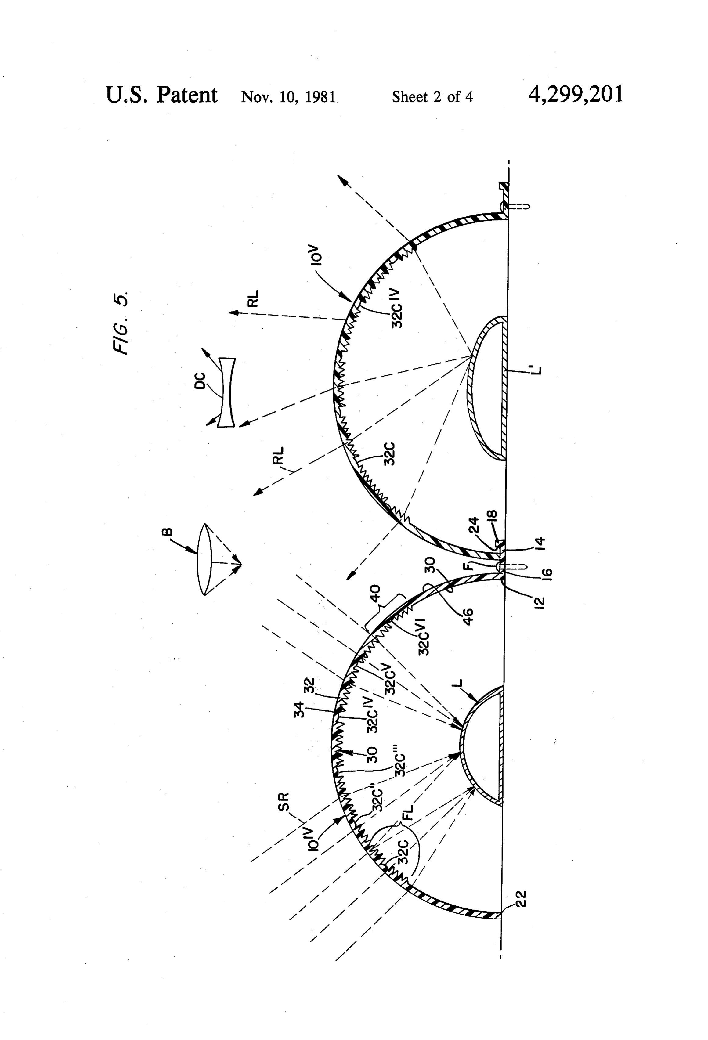
cally pleasing in appearance, and can be easily inte It is another object of the present invention to pro grated into a roof or wall of a building so as to consti vide solar energy focusing means which can present an tute part of it. outward appearance of a roof tile and function as such The preferred form of the focusing body is that of a so as to constitute part of a roof structure or outer wall Spanish-style roof tile. Thus, in the preferred form, the 65 of a building. r focusing body is semi-cylindrical in shape. The focusing It is another object of the present invention to dis body has certain multiple fine menisci defined on the pense with complicated mechanical means of pursuing surface of that focusing body which constitute centripe the position of the sun for achieving higher efficiency in 7 solar collection and thus to simplify in entirety a solar hollow inside of such focusing body provides confined collecting system, yet retaining high efficiency. air space. The total angle included by the transverse It is another object of the present invention to mini cross-section of each focusing means is about 180 de mize energy loss by way of re-radiation from the sur grees so that the focusing means forms about half of a face of a solar trapping means and enhance overall plane figure, as will be described in more detail below. efficiency of a solar collecting system. As shown in FIGS. 2 and 10, the portion of a plane It is another object of the present invention to enable figure PF may be materially less than 180 degrees. integrating a solar collecting system in a building so as As best shown in FIG. 5, the solar focusing means to constitute part of it in useful ways, such as forming each has a proximal longitudinal edge 12 having a the roof or outer wall thereof, so that it can not only be 10 mounting flange 14 integrally mounted thereon. The aesthetically pleasing, but also withstand rough weather flange 14 includes a base 16 and a lip 18 extending up and can further prevent the building from being heated wardly therefrom. A fastener F, such as a nail, or the up by solar energy, particularly in summertime, by way like, attaches the flange 14 to the roof bed to thereby of taking out solar energy for conversion thereof into attach the focusing means to the roof bed. As shown in useful utilities of energy, as well as acting as an adiabatic 15 FIG. 5, each focusing means has a distal longitudinal means of a building by way of providing confined air edge 22 which is received on the flange 14 of an adjoin space within a solar focusing body which embodies the ing collector adjacent, and preferably abutting, the present invention. inner surface 24 of the lip 18. In this manner, the solar These together with other objects and advantages focusing means are integrated into a roof as part thereof which will become subsequently apparent reside in the 20 and function as roof tiles while each solar focusing details of construction and operation as more fully here means can, if desired, straddle and thereby enclose at inafter described and claimed, reference being had to least one longitudinal pipe L of the piping heat ex the accompanying drawings forming part hereof, change system P. The solar focusing means are thus wherein like reference numerals refer to like parts securely mounted on a roof bed and interconnected throughout. , ' 25 with each other and perform the function of roof tiles, if so desired.
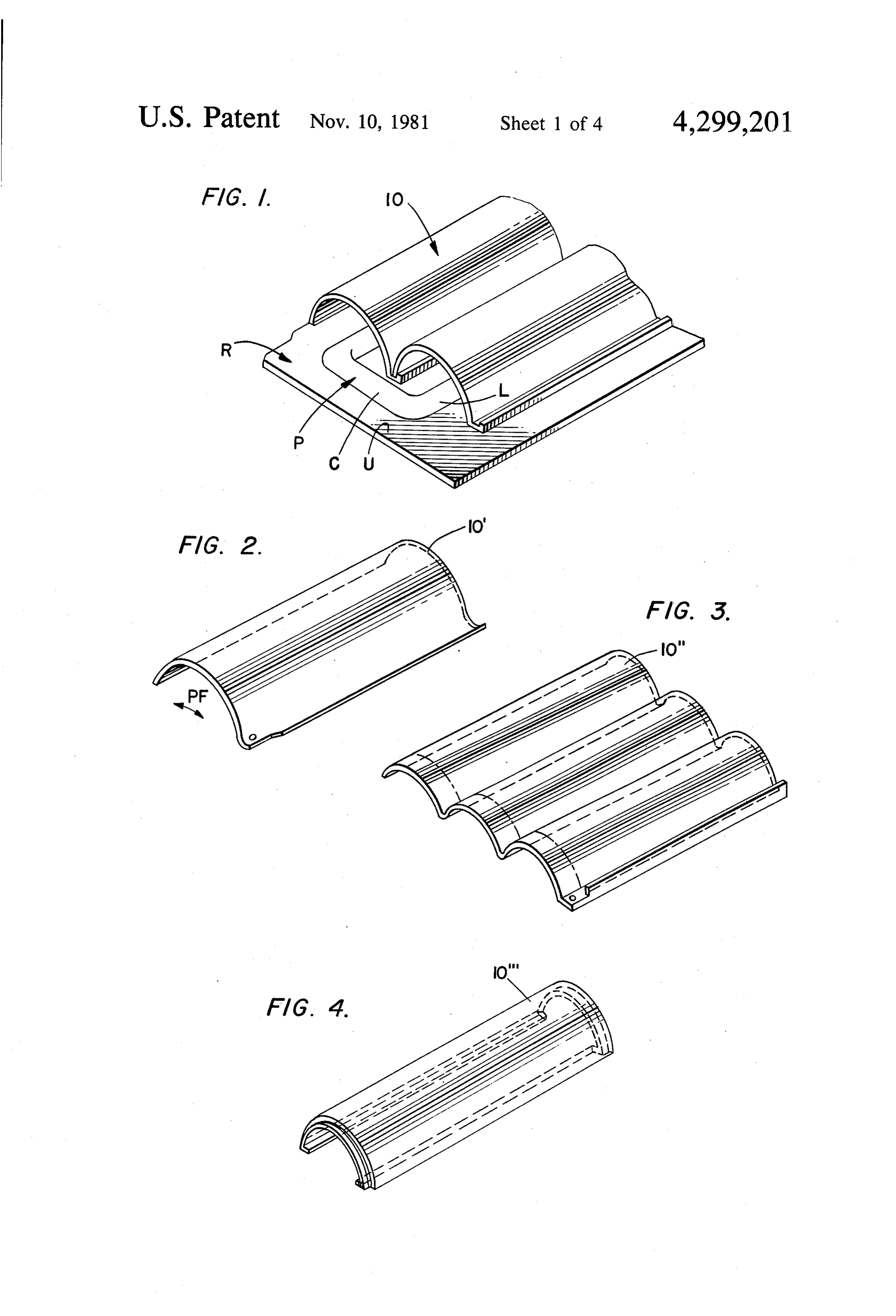
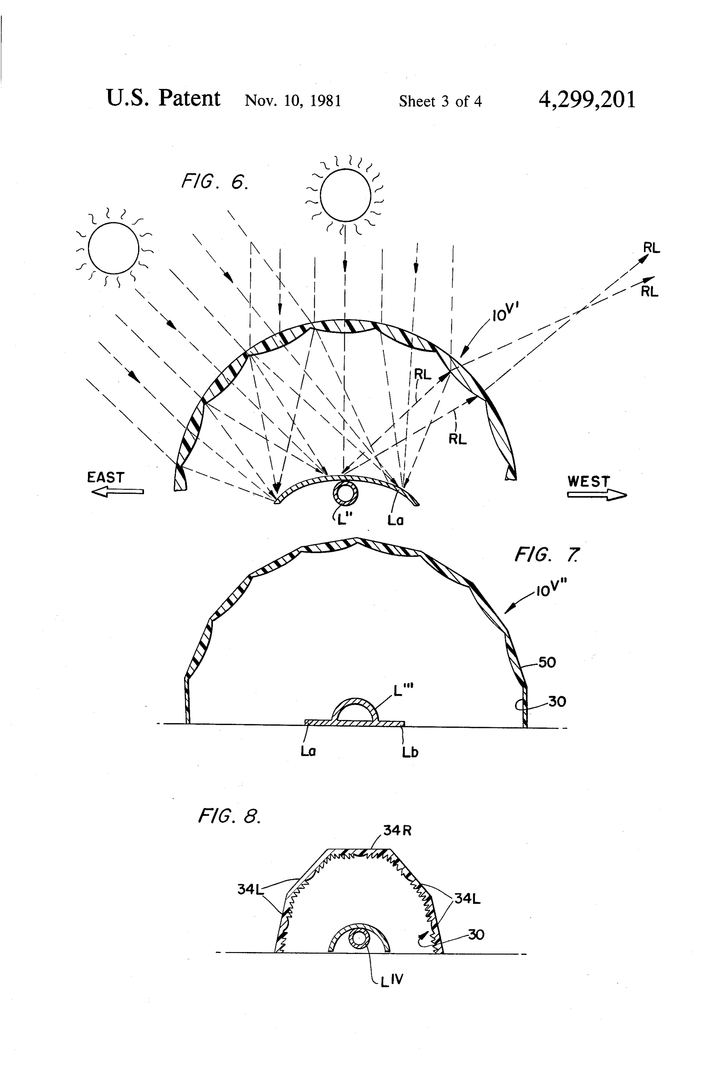
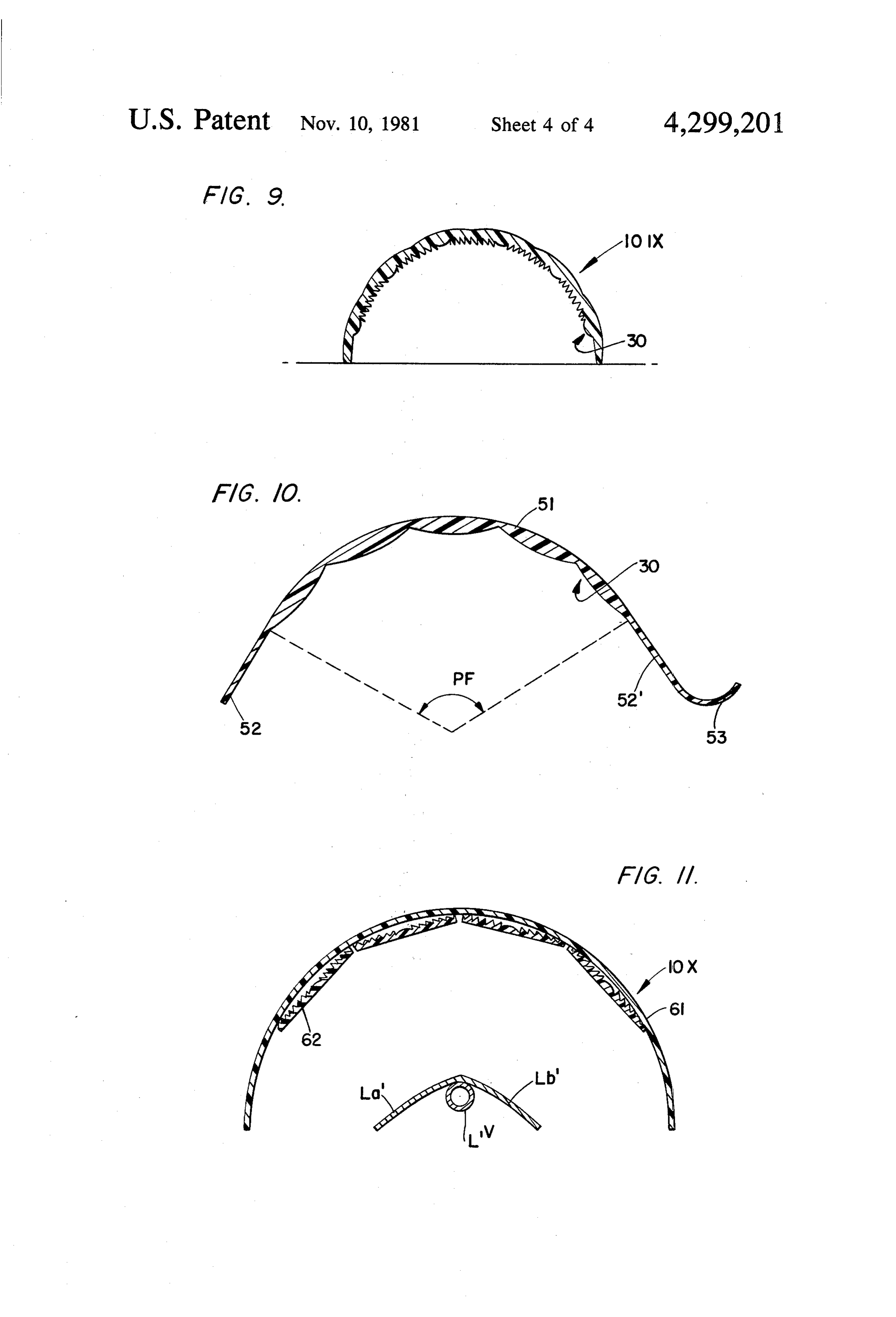
BRIEF DESCRIPTION OF THE DRAWINGS As best shown in FIGS. 5 and 7-10, the inner surface FIGS. 1-4 are perspectives of various solar focusing 30 of the body of each solar focusing means or part bodies comprising solar focusing means embodying the thereof may be so grooved by a plurality of rulings 32, teachings of the present invention. 30 and areas 32c, 32c', 32c', 32c and 32c to define a FIG. 5 shows interlocked solar focusing bodies with multiplicity of essentially parallel facets 34 which ex one form of certain fine menisci defined on the inside of tend longitudinally of the focusing means. The facets the solar focusing bodies. are spaced to define an appropriate grating spacing, and FIG. 6 is an elevation view showing another form of the thickness of the solar collector is selected so that a certain multiple menisci defined on the inside surface of 35 plurality of Fresnel gratings, or plural Fresnel lenses 40, the solar focusing body, are formed by the solar focusing means. A single unit of FIGS. 7-11 show alternative embodiments of the a Fresnel lens is indicated by the bracket indicator FL. solar focusing means embodying the teachings of the Each of the pipes L is located centering around the present invention. focuses of such lenses, and thus the lenses 40 focus 40 incident solar rays SR onto the longitudinal pipes L as
DETAILED DESCRIPTION OF THE indicated for solar focusing means 10 in FIG. 5. The INVENTION focusing means thus approximates a plurality of convex Shown in FIG. 1 is a portion of a roof bed R having lenses, such as lens B, for incident solar rays. As indi a heat exchanger pipe P mounted on the upper surface cated in FIG, 6, the inside surface of the focusing means U thereof. The heat exchanger pipe has heat exchange 45 may be so defined as to constitute a plurality of convex fluid, such as water, or the like flowing therethrough, lenses for incident solar rays. In FIG. 6, pipe L' has and is part of a heat exchange system used in a building heat absorber La. The solar energy thus focused in such as a house, apartment, commercial building, fac multiple beams onto the pipes L' heats the fluid con tory, or the like. The fluid flowing in the pipes P is tained therein.
heated by solar energy and exchanges that heat with 50 Thus, as indicated in FIGS. 6 and 7, no matter what suitable equipment for heating water, or the building position the sun assumes with respect to the focusing itself, in ways which will occur to those skilled in the art means, the convex nature of the lenses causes incident from reading this disclosure. Heat can be given up by solar rays to be focused in multiple beams onto the pipes the fluid in the pipes P to the environment surrounding L" and L" to thereby heat the fluid flowing there them in many instances, if so desired. On the upper 55 through at all times during the sunshine hours. Thus, surface of pipes P, semi-conductors converting solar efficient heating of the heat transfer fluid is effected by rays to electricity may be placed for the conversion of the solar focusing means for the entire period of day. solar energy in another form. light.
The pipes P include longitudinal pipes L and con The solar focusing means 10 constitute an aestheti. necting pipes C which fluidly connect the ends of the 60 cally pleasing roof because of their semi-cylindrical or longitudinal pipes together to define a continuous flow gutter-like shapes and the lenses defined therein. As path through the piping system. just-discussed, for incident solar rays, in case the Fres A plurality of solar energy focusing means 10 are nel lenses are defined on the focusing body, they act like mounted on the roof upper surface to straddle each double convex lenses to focus that energy onto the pipes longitudinal pipe L. The focusing means 10 are hollow, 65 L. However, for reflected light RL as indicated for the and elongate, and extend nearly the entire length of the solar focusing means 10 in FIG. 5, such Fresnel lenses longitudinal pipes, leaving just enough clearance at the 40 spread reflected light, indicated as DC in FIG. 5, ends thereof for the transverse connecting pipes C. The Reflected light is thus dispersed and the rays scattered 8 by the Fresnel lenses. In case focusing means such as equivalents are, therefore, intended to be embraced by convex lenses as shown in FIG. 6 are defined on the those claims.
focusing body, reflected light is also dispersed out I claim:
wardly for the point beyond the outer focus thereof, as 1. A solar energy focusing means comprising: indicated in FIG. 6. a hollow solar energy focusing body, having a trans The dispersal of light rays reflected from the pipes L verse cross-section which includes a substantial gives the overall roof a uniform appearance having a fraction of a plane figure, said focusing body strad color corresponding to the color of the pipes L. Thus, dling a portion of a solar energy conversion device copper pipes will give the overall roof a copper hue so that solar energy is incident upon said focusing when a building incorporating the solar collection fo 10 body prior to being incident upon such conversion cusing means herein described is viewed. The color of device portion;
the focusing means is uniform over the outer surface 46 a multiplicity of fine menisci defined in said solar of the focusing means bodies and the overall roof can energy focusing body to be in a plurality of groups have the appearance of a Spanish-style roof, or the like. with spacing between said groups, said menisci Of course, other colors for the pipes can be used with being ground and angled to define a plurality of out departing from the scope of the present disclosure. 15 biconvex lenses for incident solar energy and a The focusing means shown in FIG. 5 are semi-circu plurality of biconcave lenses for solar energy lar in transverse cross-section, but other shapes can be which is reflected from said solar energy conver selected for the focusing means. Examples of such other sion device, said plurality of bi-convex lenses hav shapes are shown in FIGS. 7-11. Thus, FIG. 7 shows a ing a plurality of focuses on said focusing body to focusing means 10 comprising a multiplicity of planar 20 focus incident solar rays in multiple beams onto sections 50 integrally edge coupled together to define such conversion device portion in the manner of an arcuate semi-cylindrical shape similar to the semi convex lenses, said multiple focuses applying multi cylindrical shape of the focusing means shown in FIGS. ple focused beams onto the solar energy conver 1 and 5. The pipes L' shown in FIG. 7 are also semi sion device at all times irrespective of the position cylindrical in shape and have fins Lb and La to act as 25 of the sun so that the sun need not be tracked, said heat absorbers, but other shapes can also be used for the concave lenses dispersing said reflected solar en pipes P without departing from the scope of the present ergy so that said focusing body has an outward disclosure. overall coloring corresponding to the coloring of As indicated best in FIGS. 7 and 8, the focusing body such conversion device portion straddled by said may be defined so that facets 34L slope away from facet 30 focusing body.
34R on multi-sectional focusing means each having 2. The solar energy focusing means defined in claim planar outer surfaces. The slope of the facets may be 1, wherein the upper part of such focusing body has altered so the desired focusing operation can be ob about one-third of a plane figure and the lower part tained. The size, number, shape and relative orientation thereof is an extension of such plane figure in any de of the facets and grooves of the various focusing means sired form.
disclosed herein can be set to obtain the desired results 35 3. The solar energy focusing means defined in claim for focusing and reflecting light. 1, wherein said plane figure is about one-half of a circle FIG. 9 shows a semi-cylindrical focusing means 10K so that said focusing body is approximately semi-cylin wherein the focusing body is essentially semi-cylindri drical in shape.
cal and the focusing means are defined on both surfaces. 4. The solar energy focusing means defined in claim FIG. 10 shows a collector means having semi-planar 40 1, wherein said plane figure is arcuate. portion 51 with the total angle PF of about 120 degrees and having planar portions 52 and 52", with smaller 1, 5.wherein The solar energy focusing means defined in claim said plane figure is centripetally multi-sided.
semi-planar portion 53. 6. The solar energy focusing means defined in claim FIG. 11 shows another focusing means 10 imple menting the present invention, wherein a multiple num 45 a1,fluid wherein the solar energy conversion device includes flow pipe of semi-cylindrical shape.
ber of lenses 62 are attached to a surface cover 61 in a semi-cylindrical shape so that a multiple focusing body wherein saidsolar 7. The energy focusing device of claim 1, convex lenses are defined on said focusing is comprised of a transparent cover and multiple lenses body.
attached to it in a centripetal form. 8. The solar energy focusing device of claim 1, The pipes L through L can be used with any of the 50 wherein said convex lenses are attached to said focusing focusing means shown if so desired. body.
The Fresnel gratings on the focusing means can be 9. The solar energy focusing means of claim 1 ruled or formed according to methods known to those wherein the solar energy conversion device includes a skilled in the art. Such methods are described in Light, fluid flow pipe with solar energy absorbing means by R. W. Ditchburn, published by Blackie and Son 55 thereon.
Limited in 1967 (copyright 1963). Other methods also 10. The solar energy focusing means defined in claim can be used to form the gratings on the surfaces of the 1, wherein said solar energy focusing body has a shape focusing means. It is noted that the just-referenced similar to that of a Spanish roof tile.
Ditchburn text also discusses the theory of Fresnel 11. The solar energy focusing means defined in claim deflection and lenses, and attention is directed thereto 1, further including fastening means for attaching said for such discussion. 60 focusing means to a roof bed of a building.
As this invention may be embodied in several forms 12. The solar energy focusing means defined in claim without departing from the spirit or essential character 11, wherein said fastening means includes a flange on istics thereof, the present embodiments are, therefore, one longitudinal edge of said focusing body with an illustrative and not restrictive, since the scope of the other longitudinal edge of said focusing body being invention is defined by the appended claims rather than 65 free, said free edge of one body being received in said by the description preceding them, and all changes that flange of an adjacent body to interlock the two adjacent fall within the metes and bounds of the claims or that bodies together.
form their functional as well as conjointly cooperative k sk ck k sk
Provenance
- Collection
- Patents citing this work
- Pages
- 8
- Method
- pdftotext (the PDF's own text layer) + pdftoppm 300dpi page scans
- Patent office record
- patents.google.com →
- Source
- Google Patents citing-documents table
- Assignee
- Junjiro Tsubota
- Published
- 1981-11-10
- Transcribed from
- patentimages.storage.googleapis.com →