

patent · US4341201A
Solar energy collecting and utilization system
27 July 1982
Text
Page 1bibliographic recordscan →
United States Patent (19)
Ziemann
54 SOLAR ENERGY COLLECTING AND
- UTILIZATION SYSTEM
Inventor: Ronald W. Ziemann, 4307
Moonbeam Dr., Colorado Springs,
Int. Cli................................................. F24J 3/02 52 U.S. C. .................................... 126/422; 126/427;
2,509,460 5/1950 Transue............................... 219/338 3,934,573 1/1976 Dandini............................... 126/440 3,981,295. 9/1976 Minnick .............................. 126/419 4,057,048 11/1977 Maine .................................. 126/440
4,205,661 6/1980. Chapman ............................ 126/440 4,211,212 7/1980 Braun .................................. 126/440
FOREIGN PATENT DOCUMENTS
Primary Examiner-Carroll B. Dority, Jr.
Attorney, Agent, or Firm-William G. Gapcynski;
Werten F. W. Bellamy
A solar energy collecting and utilization system is pro vided which comprises a lens matrix formed by a plural ity of lens units disposed in a generally planar array. Each unit comprises a plurality of lenses arranged in a dome-like configuration and having a common focal length. A solar heat collection surface, formed by a thin metallic (e.g. copper) sheet, is shaped to conform to the curve defined by a line drawn through the focal points of the lenses. A viscous liquid (e.g., a vegetable oil) is circulated in contact with the heat collecting foil to extract heat therefrom. A back-up system includes a plurality of infra-red lamps and associated lenses which focus the light from the lamps onto a further heat col lecting surface in contact with the circulating, heat extracting liquid.
8 Claims, 5 Drawing Figures
Drawings
Page 2drawing sheetscan →
Page 3drawing sheetscan →
Page 4drawing sheetscan →
Page 5drawing sheetscan →
Page 6scan →
aspect of the invention, the heating collecting fluid
Solarutilizationsystem
ENERGY COLLECTING AND comprises a liquid heat collecting medium selected from the group consisting of lubricating oils, vegetable oils, glycerine, and paraffin oils.
FIELD OF THE INVENTION 5 In an advantageous embodiment, the heat collecting The invention relates to solar heating systems and, surface is supported by a heat reflective support surface, more particularly, to an improved solar energy collec the heat collecting surface being disposed relative to the tion and utilization system. support surface, such that a space is defined therebe BACKGROUND OF THE INVENTION 10 above through tween which the circulating fluid referred to flows. The metallic member preferably com
With the increasing awareness of the long term prob prises a thin black copper foil and the support surface lems which must be solved in view of the finite nature of preferably comprises an aluminum surface. conventional energy sources such as petroleum, there In accordance with a further important aspect of the has been much attention focused on so-called, alterna invention, the overall system incorporates a back-up tive energy sources, such as solar energy. Although system including a further heat collecting fluid, and a many solar heat collecting systems have been devel oped and substantial improvements have been made, no infra-red heating arrangement for heating the further prior art solar heat collecting system provides the effi ment comprisesmember.
heat collecting
The infra-red heating arrange plurality of infra-red lamps and a like ciency, cost effectiveness and versatility of the present plurality of lenses for focusing the infra-red light from invention, particularly in the area of home heating use, 20 the lamps on the further heat collecting A number of solar heat collecting systems use lenses tageously, the further heat collectingsurface. member Advan com to collect and focus the rays of the sun onto a heat prises a thin black copper foil, and the system further collecting surface. Some examples of such systems are comprises a support surface for supporting the copper disclosed in U.S. Pat. Nos. 3,981,295 (Minnick); foil in spaced relationship therewith so that said heat 4,029,077 (Gorniak); 4,057,048 (Maine); 4,134,393 25 collecting fluid flows in a passage defined therebe (Stark et al); and 4,136,670 (Davis). The Maine and tween, this passage being inclined to the horizontal so as Davis patents both disclose solar heat collectors utiliz ing a hemispheric array of lenses, the focal lengths of to enhance flow of the viscous heat collecting fluid. the lenses being chosen so as to focus the radiant energy The system further comprising a storage container for the liquid heating collecting medium and a pump for from the sun onto a collecting surface such as a shallow 30 circulating ray of water or a collector dish. A number of other solar the medium. The heat extracting means heat collecting surfaces or bodies have been used in further comprises a fluid heating system such as a cluding metallic foils (see, for example U.S. Pat. No. forced air or steam heat system that is connected in heat 3,129,703 to Tabor). Further, many prior art systems exchange relationship with the heating collecting me provide for circulating a heating collecting fluid such as 35 dium in the storage container. A thermostatically con water in contact with the heat collecting surface to trolled system is advantageously employed for control provide for transfer of the collected heat (see, for exam ling energization of the infra-red lamp in accordance ple, the Starket al, Tabor, Minnick and Gorniak patents with the sensed temperature of the heat collecting fluid. referred to above). Although the various systems dis The system of the invention provides a number of closed in these patents possess certain advantages, these 40 advantages over the prior art. For example, the use of a systems generally suffer the common disadvantages of plurality of lenses of common or constant focal length is the prior art with respect to factors such as efficiency, considerably less expensive than the hemispherical cost, cost effectiveness and versatility. array of lenses of varying focal length provided in the SUMMARY OF THE INVENTION Maine and David patents discussed above. As described 45 in more detail hereinafter, the lens arrangement of the
According to the invention, a solar energy collecting invention not only maximizes the socalled "green and utilization apparatus is provided which substan house" effect commonly used inflat plate collectors by tially reduces or overcomes the problems and short reducing the air space between the lens and collector comings of prior art systems. surfaces but also provides manufacturing and installa In accordance with a preferred embodiment of the 50 tion advantages.
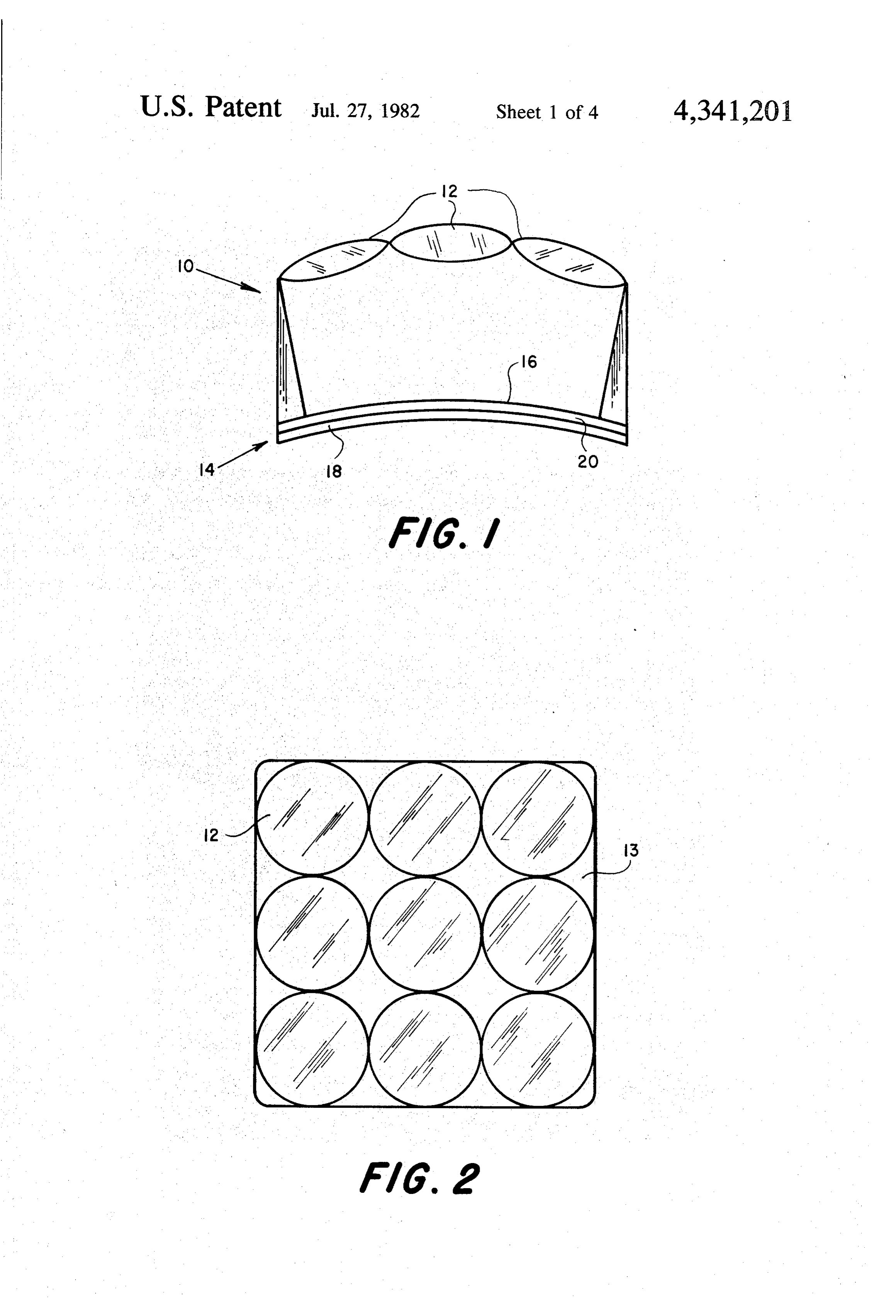
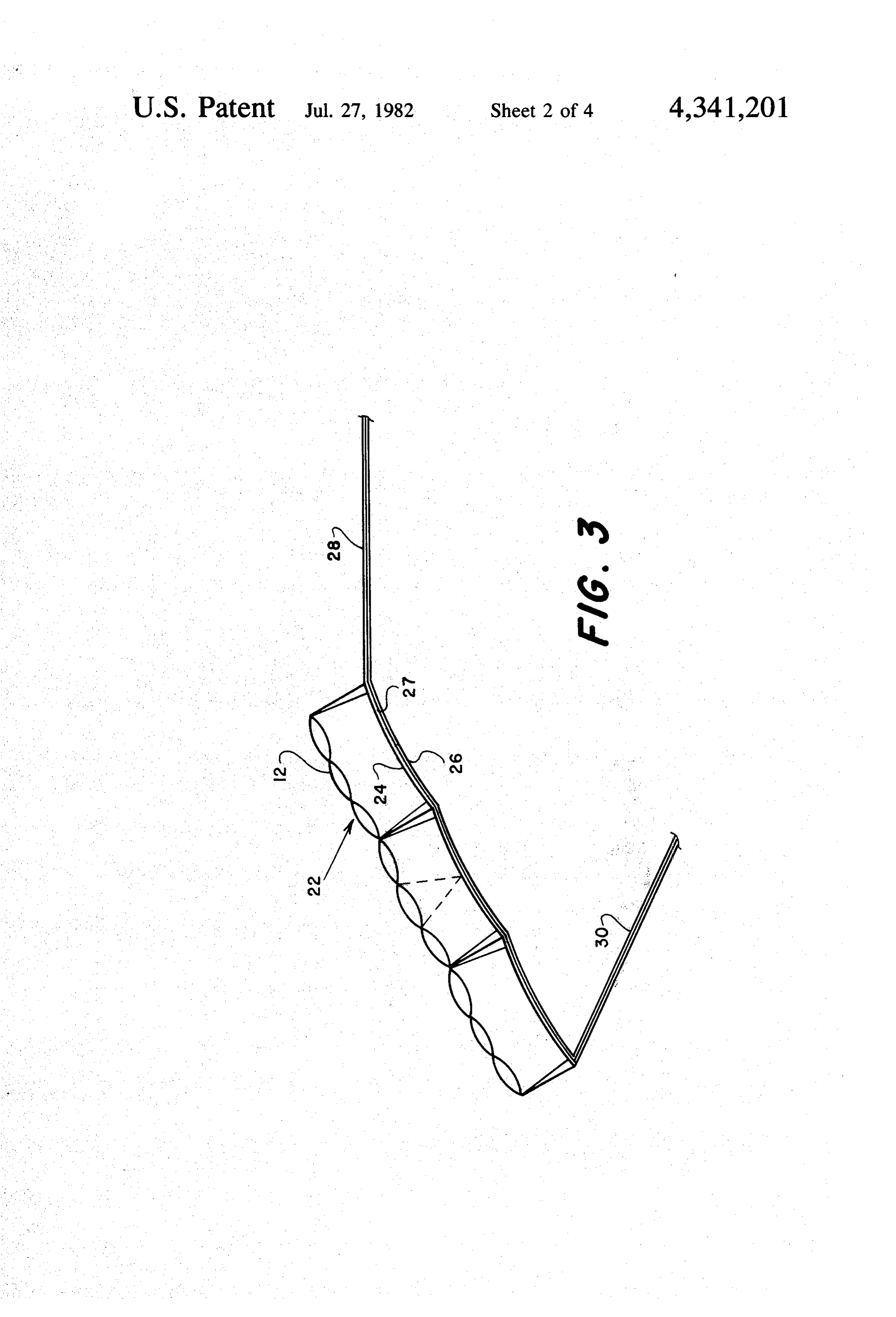
invention, a solar energy collecting and utilization sys Other features and advantages of the invention, will tem is provided which comprises a lens matrix formed be set forth in, or apparent from, the detailed descrip by a plurality of lens units disposed in a generally planar tion of the preferred embodiments which follows. array, each of the lens units comprising a plurality of lenses, preferably double convex lenses, having a com 55 BRIEF DESCRIPTION OF THE DRAWINGS mon focal length and being arranged in dome-like con FIG. 1 is a side elevational view of a solar energy figuration; a solar heat collection surface for receiving collecting unit in accordance with the invention; solar energy focused thereon and shaped to conform to FIG. 2 is a plan view of the solar energy collecting the curve defined by a line drawn through the focal unit of FIG. 1;
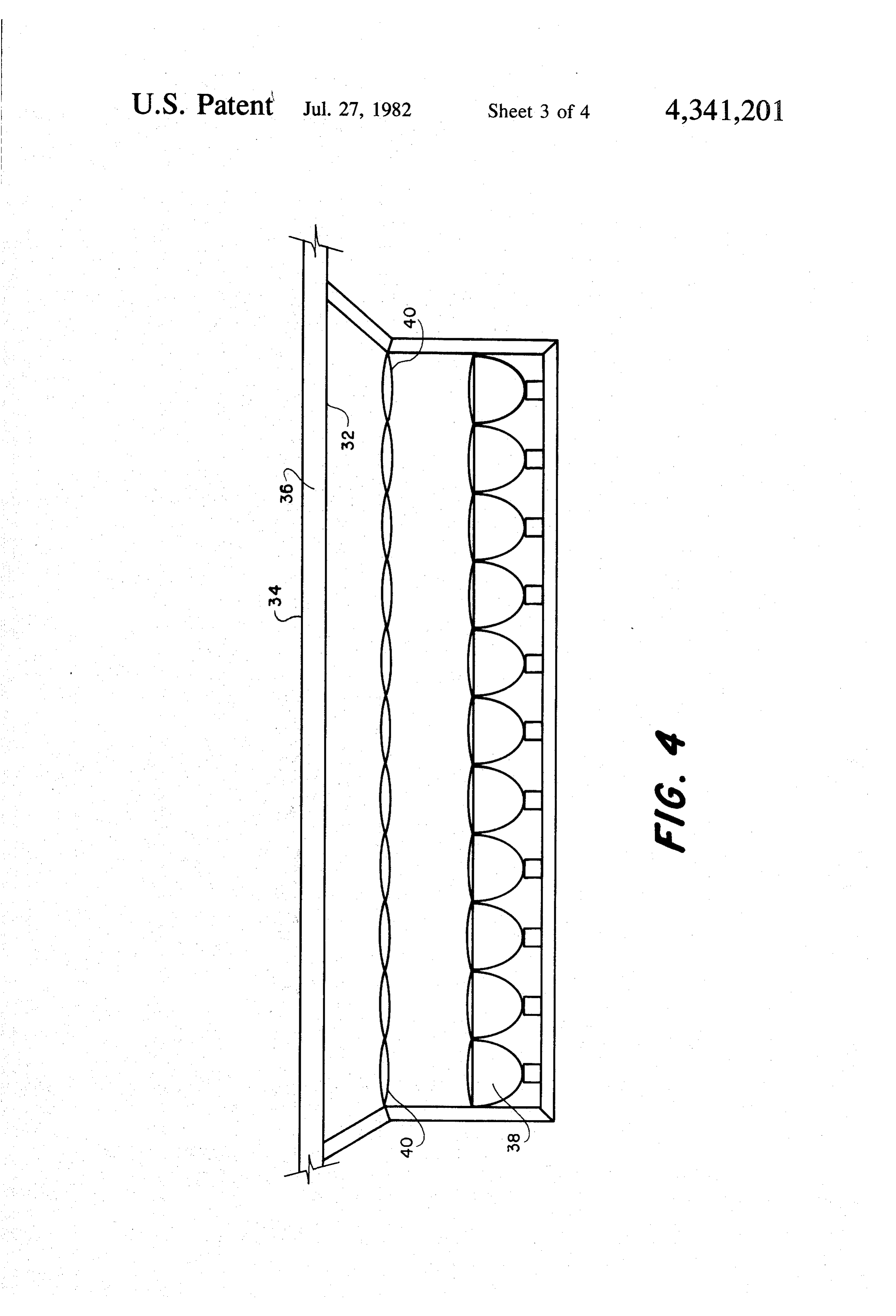
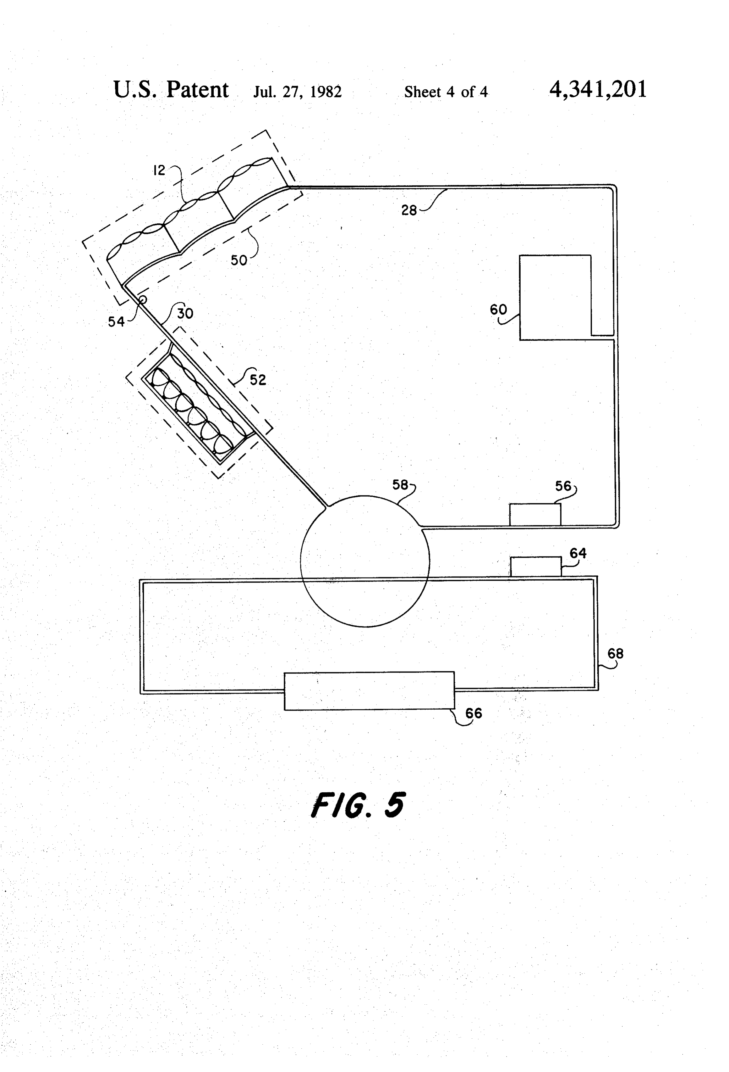
points of the lenses of the plurality of lens units; and FIG. 3 is a schematic diagram, in side elevation, of a means for extracting the radar solar heat collected by solar heat collector comprising a matrix or array of the solar heat collection surface. solar collecting units corresponding to those of FIGS. 1 The solar heat collecting surface preferably com and 2; '. prises one surface of a thin metallic member (foil) and FIG. 4 is a side elevational view of a back-up heatin the solar heat extracting means advantageously com 65 system in accordance with a further aspect of the inven prises a heat collecting fluid circulated in contact with tion; and the surface of the metallic member opposite to the heat FIG. 5 is a schematic diagram of an overall solar collecting surface. In accordance with an important energy home-heating system incorporating the solar 7 heat collector of FIG.3 and the back-up system of FIG. As discussed above in connection with FIGS. 1 and 2, 4. ‘. . . a space, denoted 27, is again defined between the copper DESCRIPTION OF THE PREFERRED foil collecting surface 24 and the aluminum support 26 and this space 27 is connected to suitable conduits, such
EMBODIMENT as formed by copper tubing, for a circulating heat col Referring to FIGS. 1 and 2, there is illustrated a lens lecting medium. The conduits, denoted 28 and 30, are unit which forms a building block in constructing the connected in an overall systern which is described solar heat collecting system of the invention. The lens below in discussing FIG. 5 and which includes a back unit, which is generally denoted 10, includes a plurality up heating arrangement shown in FIG. 4. of double convex lenses 12 of constant focal length, 10 Before considering the overall system in more detail, supported by suitable means indicated at 13. In the the circulating medium itself should be discussed. Tra specific embodiment illustrated, each unit comprises ditionally, most conventional solar heating units use nine lenses 12 arranged to form a square as shown in water as the circulating medium. Although water does, FIG. 2. Each unit 10 also includes a heat collecting of course, possess a number of advantages, the system of surface 14 comprising a very thin black, copper foil 16 15 the invention requires a medium having different physi supported on a reflective aluminum support surface 18. cal properties from those of water. In particular, the The aluminum support surface 18 provides the neces medium must have a high boiling point (150-350 F) sary support and insulation for a circulating heat col to accommodate the increased range of temperatures to lecting medium described below because of the reflec which the system is to be subjected. In this regard, the tive and negative thermal conductive characteristics 20 concentration of the solar energy provided by the lens thereof. The copper foil 16 is located at the focal length matrix results in a foil temperature of between 300 F. of the lenses 12 of lens, unit 10. The copper foil 16 is and 1000 F. on a sunny day. The medium must also disposed in contact with support surface 18 such that a have a higher viscosity and hence a slower flow rate so narrow but definite space 20 is provided therebetween as to allow for conduction of heat from the copper foil through which the heat collecting medium mentioned 25 collecting surface to the circulating medium. This above circulates. It will be understood that the showing higher viscosity also permits the formation of a thin film in FIG. 1 of foil 16, support surface 18 and space 20 is throughout the space 27 between the collecting surface highly schematic and that, for example, foil 16 and 24 and the support 26, thereby facilitating rapid and space 20 are more narrow in cross section than is uniform heat transfer with minimum energy loss. Pref. shown. - 30 erably, the medium is one selected from the group con As shown in FIG. 3, the lens units 10 are combined sisting of lubricating oils, vegetable oils such as olive together in a solar heating collector matrix or array 22. oil, glycerine, and paraffin oils. In general, these com The lenses 12 of units 10 are arranged, along a hyber positions possess the necessary properties discussed bolic curve rather than in a hemisphere as is the case above and at the same time are inexpensive enough to with prior art solar collectors such as discussed above. 35 be cost effective. . Further, as illustrated in FIG.3, a copper foil collecting Referring to FIG. 4, the back-up arrangement men surface 24, corresponding to individual foil 16, is sup tioned above is shown in schematic form. It will be ported by an aluminum support 26, corresponding to understood that in most climates solar heating systems individual support 18, in spaced relationship to lens require a back-up heating arrangement of some kind. matrix 22. Collecting surface 24 has the same curvature Most such back-up arrangements utilize traditional as the lens matrix 22. The shape of the collecting surface heating, such as electric heat, and the necessity for the 22 can be seen to follow the curvature that would be installation of such an arrangement, thus diminishes the outlined by the focal points of the lenses 10 which make value of the solar heating system. Stated differently, up collecting surface 24. This feature not only maxi such back-up systems are not integrated with the solar mizes the so-called "greenhouse effect" as commonly 45 heating system and the necessity for two systems gener employed in flat plate collectors by reducing the air ally means that the solar system is not cost effective. space between the inner surfaces of the lenses and the This is also true for systems which use the latent heat collecting surface but also reduces production costs and developed from solar radiation itself. The present in on-site design fees. vention provides for a back-up system which utilizes the Although the lenses of the individual units 10 are 50 circulating medium which is part of the solar heat col domelike in shape (and thus the collecting surface 24 lecting system discussed above. As shown in FIG. 4, the presents a waffle-like appearance when viewed in plan), back-up arrangement includes a copper foil collecting lenses 12 are positioned along a relatively flat curve so surface 32 with an aluminum support 34, similar to the that the collecting surface 24 formed thereby is substan heat collector discussed hereinbefore. The heat collec tially planar in overall cross sectional shape. The planar 55 tor formed by collecting surface 32 and support 34 is surface so formed can thus be arranged in an advanta generally planar and is disposed so as to be gradually geous position relative to the sun depending on geo sloping, to thereby permit gravity to aid in the circula graphical location and other factors. On the other hand, tion of the viscous heating collecting medium which the dome shape of the individual units eliminates the flows through the space 36 defined between the two need for costly tracking of the sun, since at least one surfaces. The arrangement further includes a plurality lens of each unit should be focused on the collecting of serially arranged infra-red lamps 38 which are posi surface at all times of the day during any season, assum tioned so that the infra-red light therefrom is directed ing that the lens matrix is properly disposed for the towards collecting surface 32. A like plurality of lenses geographical location. It should be understood that it is 40, individual to each of the lamps 38, are used to focus the shape of the copper foil collecting surface 24 which 65 the infra-red light energy from lamps 38 onto collecting is conformed to the shape defined by the focal points of surface 32. It is noted that because of the relatively low lenses 12 and that although the aluminum support 26 is resistance of infra-red lamps 38 the energy demands are shown as having the same shape, this is not required. lower than those of previous systems and the lamps may 8 feasibly be powered by solar cells, thereby decreasing prising a heat collecting fluid circulated in contact with energy costs and increasing the versatility of the system. the surface of said metallic member opposite to said It will be appreciated that the lenses 38 concentrate the heating collecting surface; and a back-up system includ infra-red energy onto the collecting surface thereby ing a further heat collecting member having one surface multiplying the heat transfer and increasing the effec in contact with said heat collecting fluid and infra-red tiveness of the back-up system. heating means for heating said further heat collecting Turning now to FIG. 5, which illustrates an overall member; said infra-red heating means comprising a system incorporating the various aspects of the inven plurality of infra-red lamps and a like plurality of lenses tion discussed above, the solar collector of FIG. 3 is for focusing the infra-red light from said lamps on said indicated at 50 and the infra-red back-up system of FIG. 10 further heat collecting surface. 4 is indicated at 52. A thermostatic switch 54 is con 2. A system as claimed in claim 1 wherein said heat nected to conduit 30 so as to sense the temperature of ing collecting fluid comprises a liquid heat collecting the heat collecting medium and to automatically pro medium selected from the group consisting of lubricat vide switching "on" of the infra-red lamps 38 of back ing oils, vegetable oils, glycerine, and paraffin oils. up system 52 when this temperature falls below a prede 15 3. A system as claimed in claim 1 wherein the metallic termined level. Conduit 28 is connected through a member containing said heat collecting surface is sup pump 56 to a storage tank 58 for the circulating me ported by a heat reflective support surface, said heat dium. An expansion tank 60 is also provided as part of the circulating system. The storage container or tank 58 collecting port surface being disposed relative to said sup surface such that a space is defined therebetween is preferably cylindrical in shape and is as perfectly through which said circulating fluid flows.
insulated as possible. Because of the high temperatures 4. A system as claimed in claim 1 wherein said metal referred to above (300' to 1000), a steel container is lic member comprises a thin black copper foil and said practical and cost effective. support surface comprises a aluminum support surface. The heat from the storage tank is used in a conven 5. A system as claimed in claim 1 wherein said further tional heating system such as a forced air or steam heat 25 heat collecting member comprises system, as indicated schematically in FIG. 5. The sys foil, said system further comprisinga support thin black copper means for tem includes a heating grid 64 located in tank 58 in heat exchange relationship with the heat collecting medium supporting said copper foil in spaced relationship there stored therein and a pump 64 for circulating the heated with so that said heat collecting fluid flows in a passage fluid to a enclosure (house or other building) indicated 30 defined therebetween, said heat collecting fluid com prising a viscous liquid and said passage being inclined at 66 through a suitable conduit 68.
Although the invention has been described in relation to the horizontal.
to exemplary embodiments thereof, it will be under 6. A system as claimed in claim 1 wherein said heat stood by those skilled in the art that variations and collecting fluid comprises a liquid heat collecting me modifications can be effected in these exemplary em 35 dium selected from the group consisting of lubricating bodiments without departing from the scope and spirit oils, vegetable oils, vegetable oils, glycerine and paraf of the invention. fin oils, said system further comprising a storage con I claim: tainer for said liquid heat collecting medium and a pump 1. A solar energy collecting and utilization system for circulating said medium.
comprising a matrix of double convex lenses formed by 7. A system as claimed in claim 6 further comprising a plurality of lens units disposed in a generally planar a fluid heating system for a enclosure connected in heat array, each said lens unit comprising a plurality of lenses exchange relationship with the heat collecting medium having a common focal length and being arranged in in said storage container.
dome-like configuration; a solar heat collecting surface 8. A system as claimed in claim 1 further comprising for receiving solar energy focused thereon comprising 45 a thermostatically controlled switch for automatically one surface of a thin metallic member and shaped to controlling energization said infra-red lamps in accor conform to the curve defined by a line drawn through dance with the sensed temperature of the heat collect the focal points of the lenses of said plurality of lens ing fluid.
units; means for extracting the radiant solar heat com k
Provenance
- Collection
- Patents citing this work
- Pages
- 8
- Method
- pdftotext (the PDF's own text layer) + pdftoppm 300dpi page scans
- Patent office record
- patents.google.com →
- Source
- Google Patents citing-documents table
- Assignee
- Ziemann Ronald W
- Published
- 1982-07-27
- Transcribed from
- patentimages.storage.googleapis.com →