

patent · US4512335A
Solar energy collecting apparatus
23 April 1985
Text
Page 1bibliographic recordscan →
35 0-962 3 SR
United States Patent (19) 11 Patent Number: 4,512,335 Mori Date of Patent: Apr. 23, 1985 (54). SOLAR ENERGY COLLECTING 4,223,174 9/1980 Moeller ........................... 26/425 X APPARATUS 4,257,401 3/1981 Daniels ................................ 126/439 4,307,711 2/1981 Doundovlakis. ... 126/440 X 76 Inventor: Kei Mori, No. 3-16-3-501, 4,307,936 2/1981 Ochiai ............................. 126/417 X Kaminoge, Setagaya-ku, Tokyo,
Japan FOREIGN PATENT DOCUMENTS 21 Appl. No.: 482,027 14150 l/1982 Japan ................................... 26/424 (22 Filed: Apr. 4, 1983 Primary Examiner-Margaret A. Focarino Attorney, Agent, or Firm-Cantor and Lessler 30 Foreign Application Priority Data
Apr. 3, 1982 JP Japan .................................. 57-55668
Apr. 5, 1982 JP Japan .................................. 57-5625 A solar energy collecting apparatus comprising a cap Int. Cl. ................................................. F24J 3/02 sule being made of a transparent material, plurality of 52 U.S. C. .................................... 126/440; 126/424; lenses capsulated in said transparent capsule and collect 126/443; 350/96.23 sunbeams, a sunbeam collecting means and heat collect 58. Field of Search ............... 126/417, 424, 425, 440, ing means deposited at the focal point of the lens, a 126/443, 451; 350/96.10, 96.23, 96.24 photo-conductive cable which transmits the sunbeam collected by said sunbeam collecting means to the de References Cited sired place and a heat transmitting pipe which transmits
4,026,267 5/1977 Coleman ......................... 126/440 X desired place.
4,156,420 5/1979 Gunderson ... ... 126/433 X 4,201,197 5/1980 Dismer ................................ 126/451 12 Claims, 15 Drawing Figures
SatayyawadayStawawawayawa
SAA FA is
Drawings
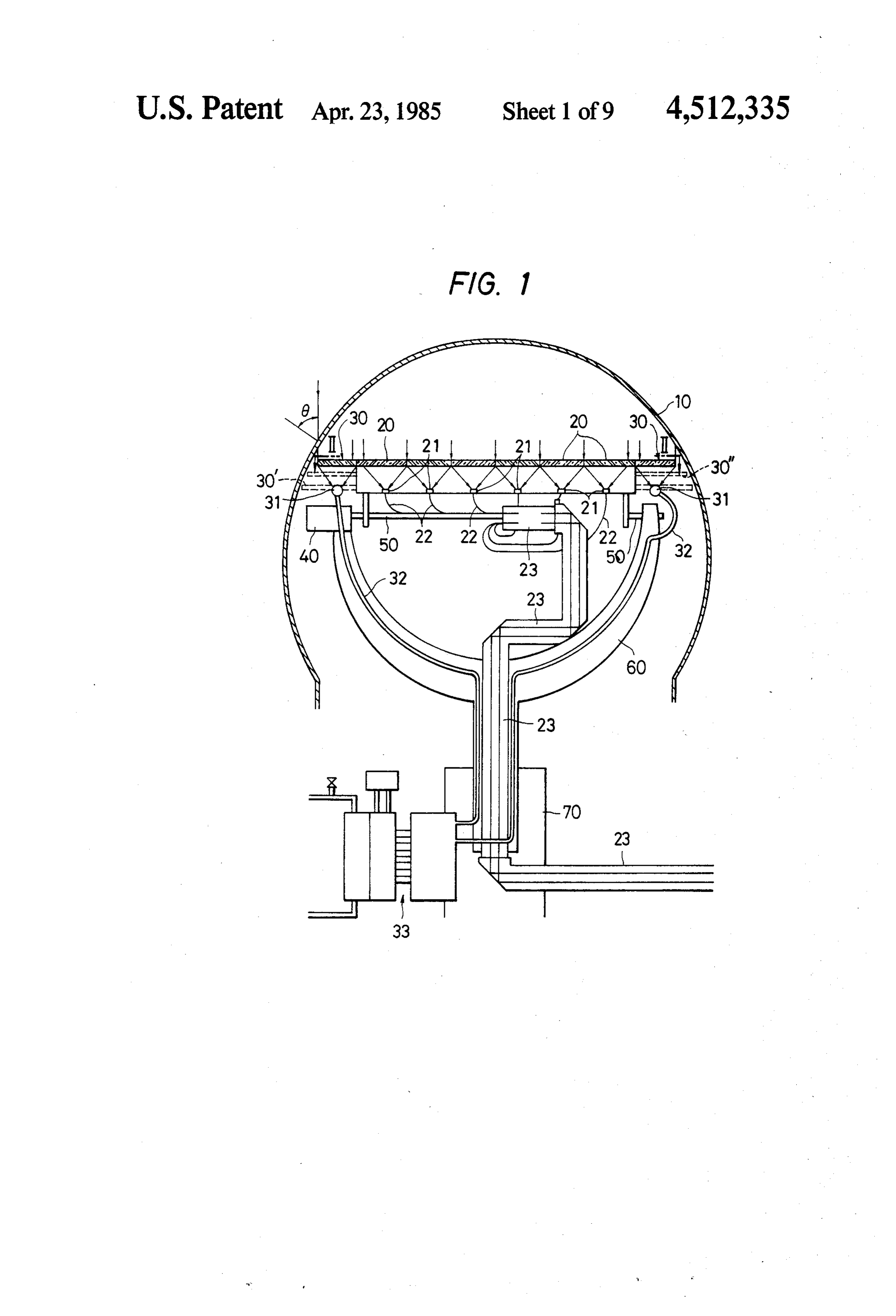
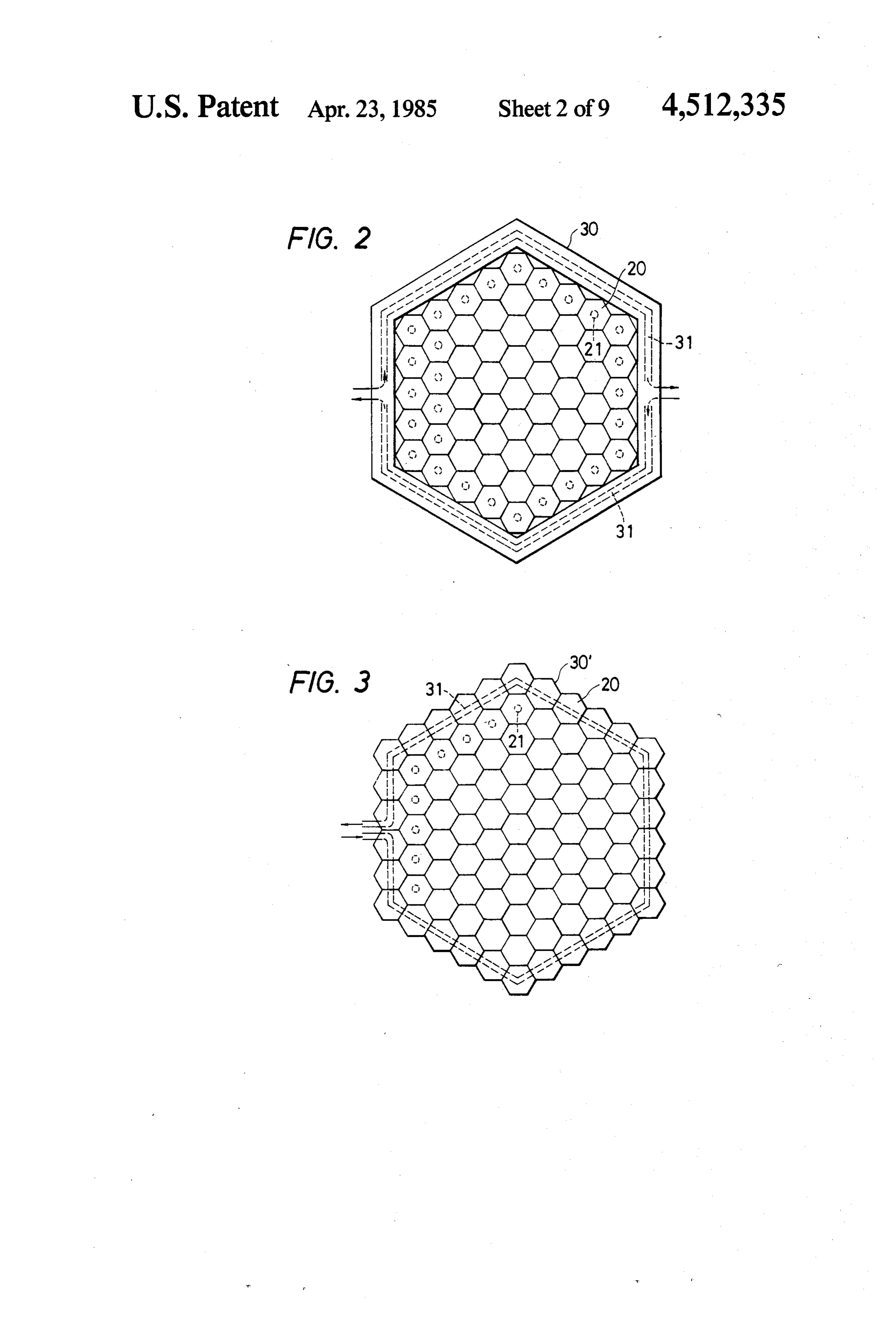
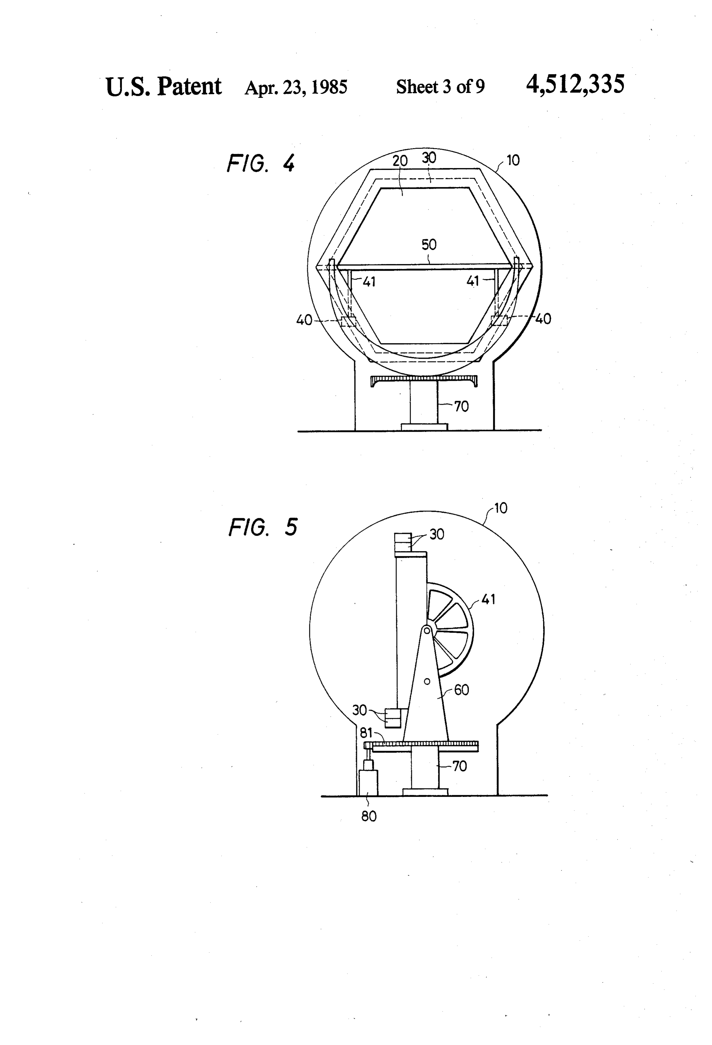
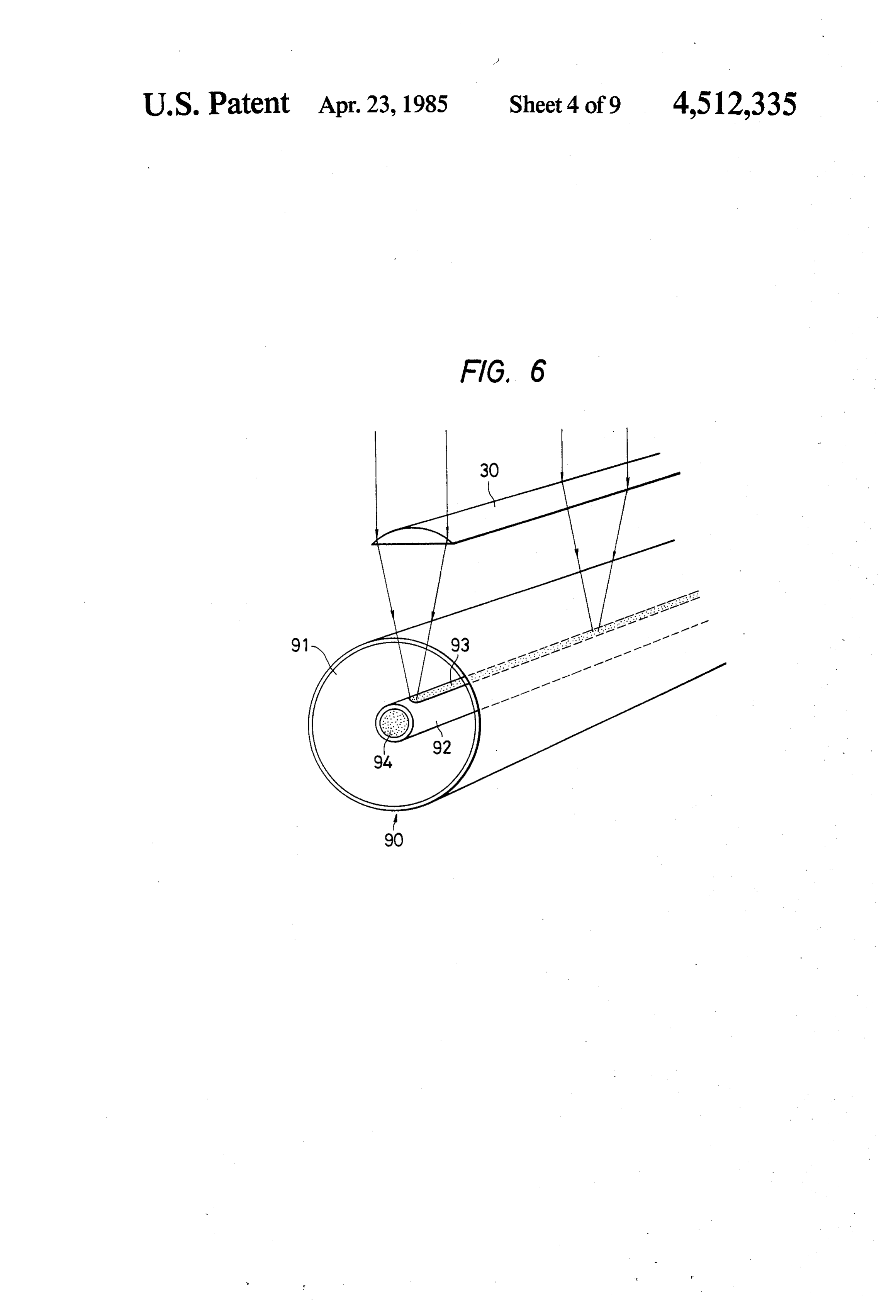
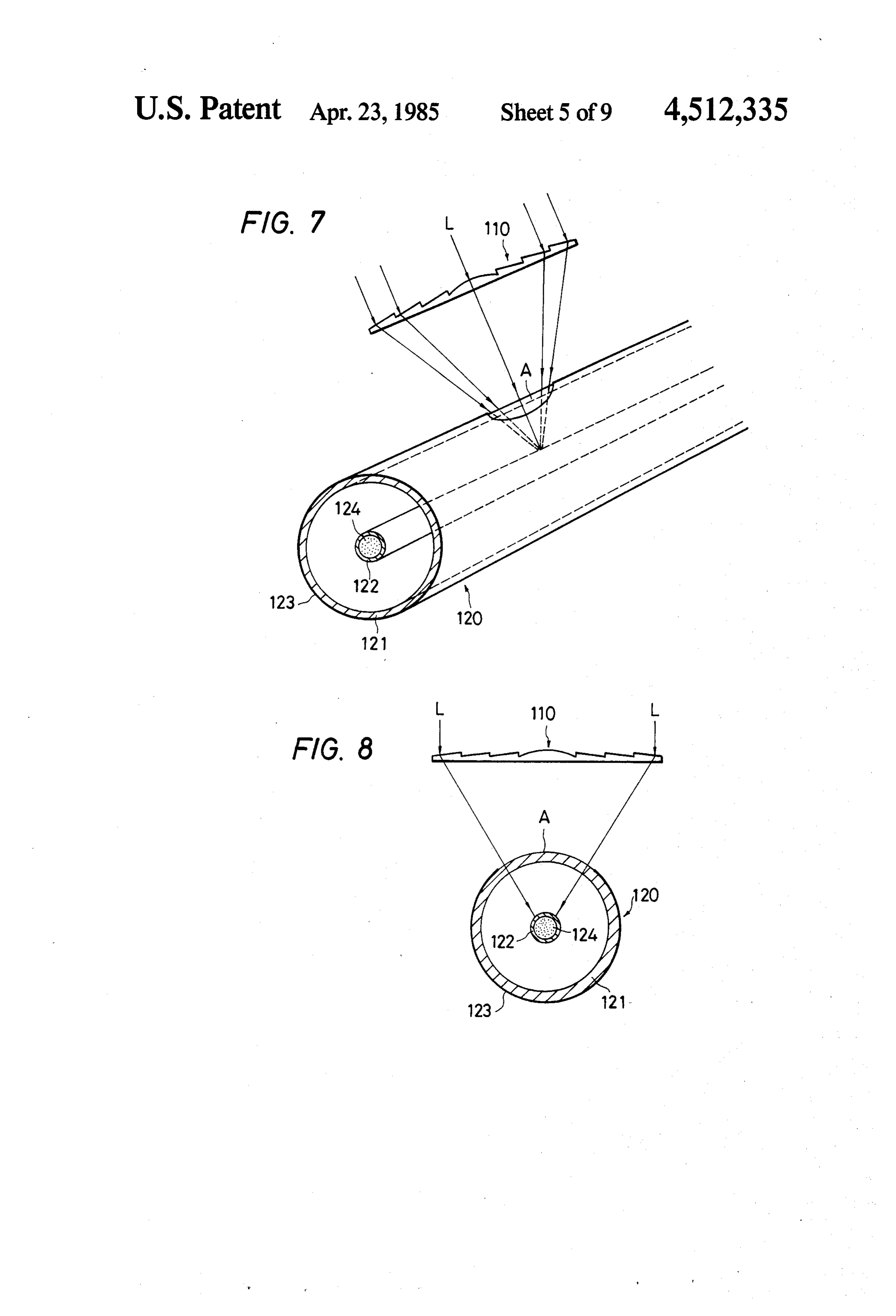
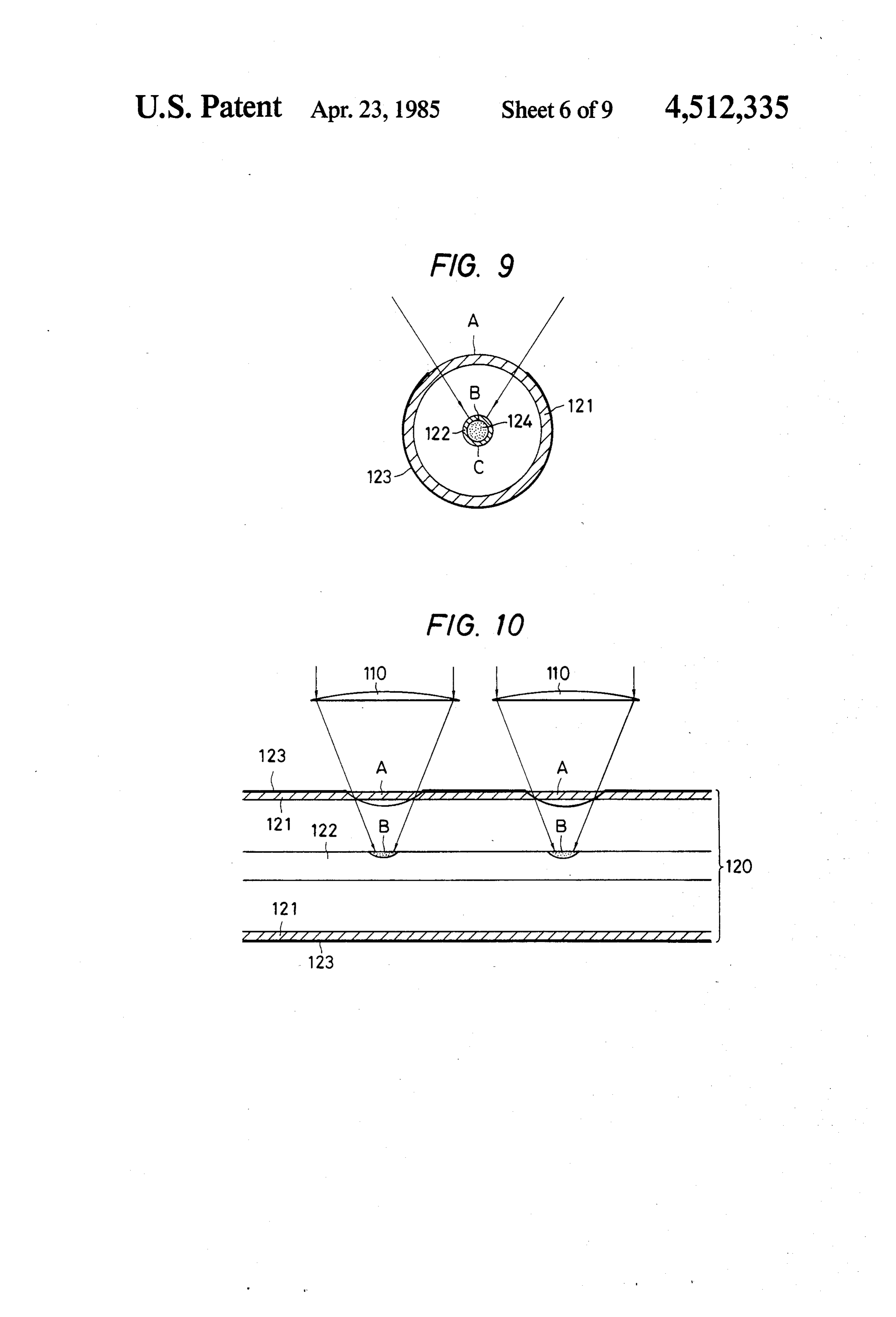
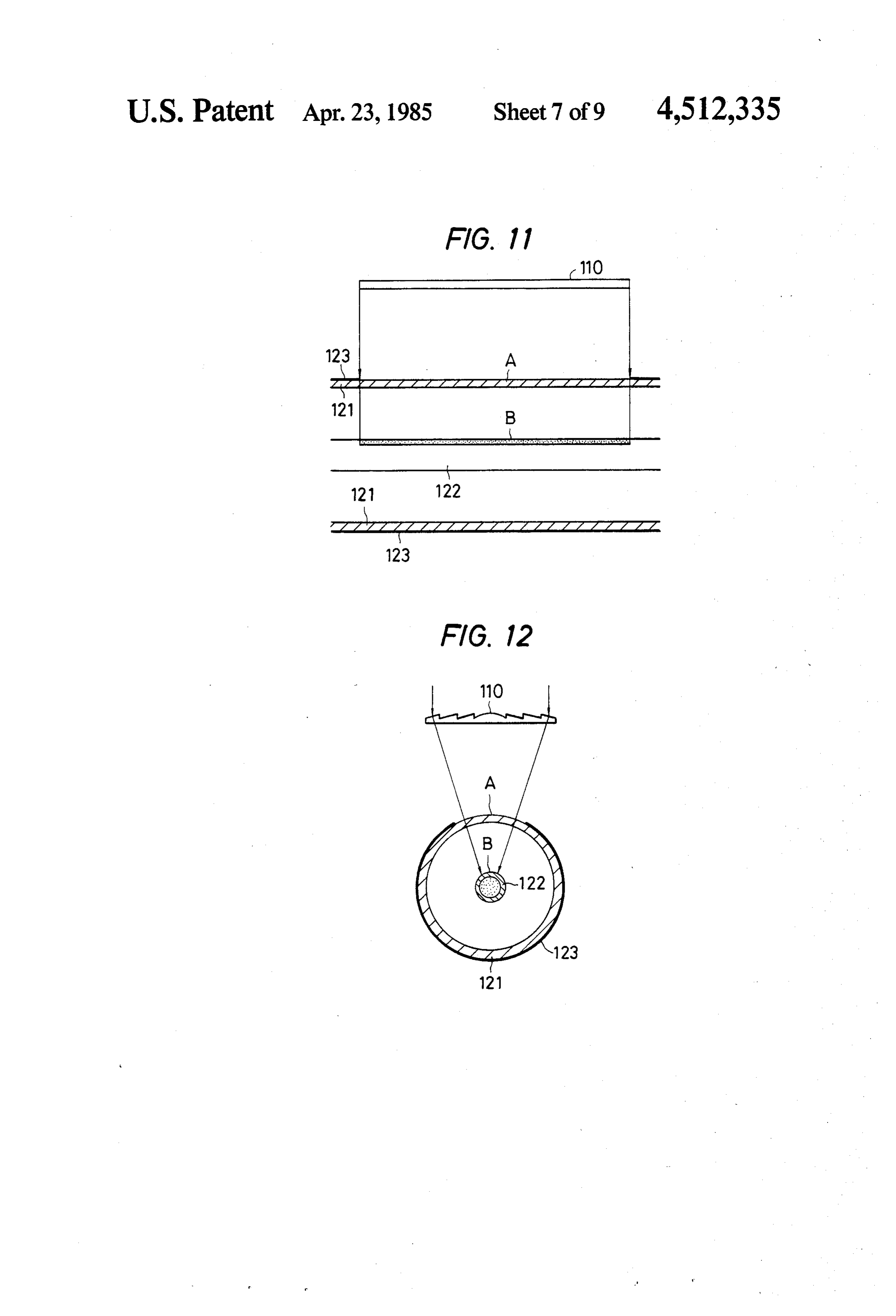
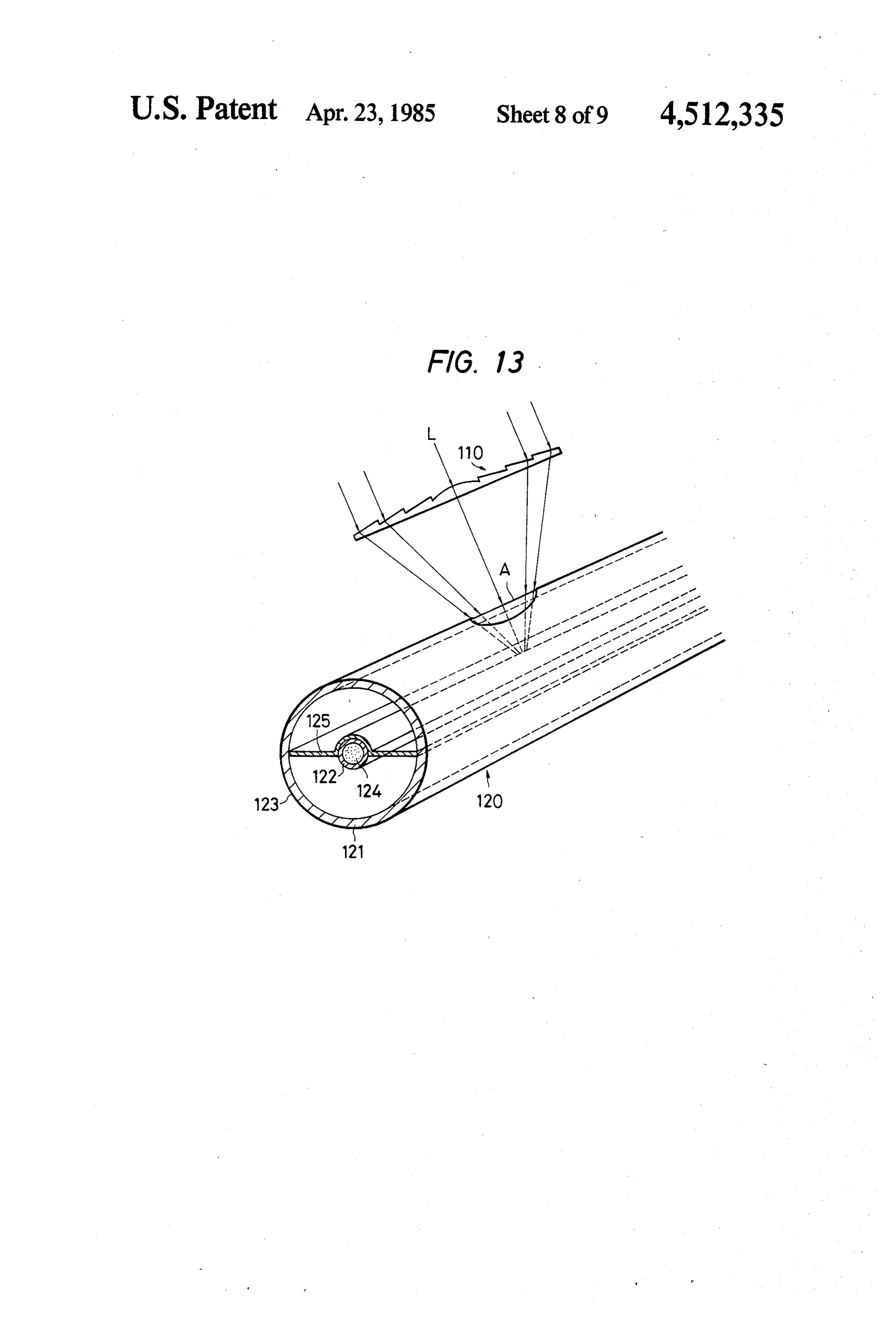
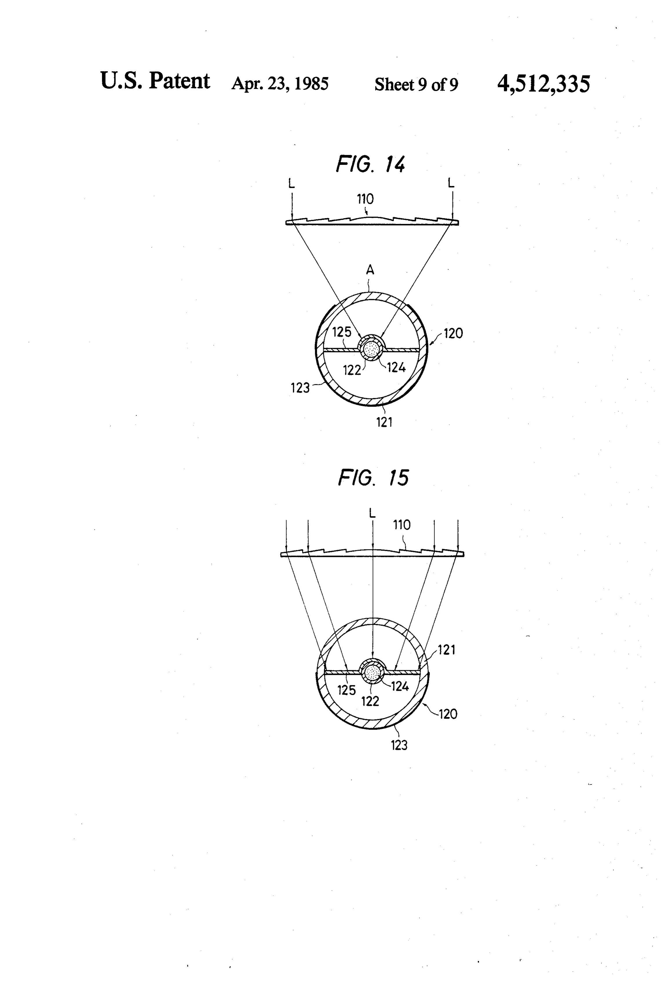
FIG. 12 is a transverse cross section of FIG. 11.
Page 2drawing sheetscan →
Page 3drawing sheetscan →
Page 4drawing sheetscan →
Page 5drawing sheetscan →
Page 6drawing sheetscan →
Page 7drawing sheetscan →
Page 8drawing sheetscan →
Page 9drawing sheetscan →
Page 10drawing sheetscan →
Page 11scan →
FIG. 12 is a transverse cross section of FIG. 11.
SOLAR ENERGY COLLECTING APPARATUS FIG. 13 is a perspective view of main portion for explaining further embodiment of the present invention.
SUMMARY OF THE INVENTION FIG. 14 is a transverse cross section of FIG. 13. 5 FIG. 15 is a transverse cross section where a linear
The present invention relates to a solar energy col Fresnel lens is used.
lecting apparatus comprising a capsule made of a trans parent material, a plurality of lenses capsulated in said DETAILED DESCRIPTION OF THE transparent capsule to collect the sun's rays, a sunlight INVENTION collecting means and a heat collecting means deposited 10 FIG. 1 is a schematic diagram of a side elevation of at the focal point of the lens, a photoconductive cable the main part for explaining an embodiment of a solar which transmits the sunlight collected by said sunlight collecting means to the desired place and a heat trans energy collecting apparatus of the present invention, in mitting pipe which transmits solar heat collected by said apparatus, andofFIG.
other words, the beam collecting and heat collecting 2 is a plan view of FIG. 1 viewed heat collecting means to the desired place. 15 along the line II-II. In these figures, 10 is a transparent BACKGROUND OF THE INVENTION capsule; 20 is a circular, square or hexagon (FIG. 2 With the advent of the energy saving era, possible shows shape;
hexagon shape lenses) lens having the desired 30 is a linear Fresnel lens. The lens 20 converges effort is directed recently particularly to research and the sun's rays and focuses the beam spot, and the beam development for effective use of solar energy. For the 20 collecting means 21 is provided at said focal point, most effective use of solar energy, it is a must to directly while the linear lens 30 converges the sun's rays and use the solar energy as the light energy, namely to use focuses the beam in the the solar energy without converting it to another form collecting means 31 like aform of a line and the heat of energy such as heat energy and electrical energy. such focal line. The solar energypipe heat is disposed along From this point of view, the applicant of the present 25 collecting means 21 is guided intocollected the by the beam invention has proposed various kinds of solar collecting pipe 23 via the photo-conductive cable 22 and then apparatuses where the solar energy is converged using transmitted lenses etc. and then guided into a photo-conductor, tive pipe 23tofortheutilizationdesired place via said photo-conduc in lighting or others. Mean thereafter transmitted through said photo-conductor to while, the heat energy collected by the heat collecting the place requiring the lighting and thereby such solar 30 means 31 is transmited to the heat exchanger 33 via the energy is used for indoor lighting etc. The present in heat transmitting vention is also proposed as a part of such apparatuses as the heat sourcepipe 32 such as a heat pipe and is used in said heat exchanger 33.
and particularly an apparatus where a means for con Here, said solar energy collecting apparatus provides verting the solar energy to heat energy is effectively a solar direction detecting system, not illustrated, which employed into the aforementioned sunlight collecting 35 controls said lens system in such a way as always direct apparatus, and thereby both light energy and heat en ing it to the sun in order to most effectively collect the ergy of the sun can be used simultaneously only with a solar energy. For this object, the lens assembly consist single apparatus. ing of the lens systems 20 and 30 is supported by the OBJECT OF THE INVENTION motor 40 freely rotably around the shaft 50; these lens assembly, motor 40 and rotating shaft 50 are supported
It is an object of the present invention to provide an by the supporting arm 60 in such a manner as freely apparatus for effectively utilizing solar energy by con rotatable around the rotating shaft 70 crossing said ro prising the means for collecting effectively light energy tating shaft 50 at a right angle. Thereby, the lens assem and heat energy of the sun into the transparent capsule. bly is now capable of tracking automatically the move BRIEF DESCRIPTION OF THE DRAWINGS 45 ment of the sun. The applicant of the present invention has already proposed various kinds of apparatuses con
FIG. 1 is a schematic side elevation of the main part cerning a solar energy collecting appratus wherein the for explaining an embodiment of the solar energy col lens system is housed within the capsule and said lens lecting apparatus to which the present invention is ap assembly is capable of tracking automatically the direc plied. 50 tion of the sun. However, in case the lens system is FIG. 2 is a plan view of FIG. 1 viewed along the line accommodated in the capsule, the sunbeam direction is II-II. disturbed when it passes said capsule, particularly the FIG. 3 is a plan view of the main portion indicating sunbeam entering the peripheral part of the lens assem another embodiment of the present invention. bly is reflected by said capsule because the incident FIG. 4 and FIG. 5 are schematic diagrams of struc 55 angle 6 to the capsule 10 is too large. Therefore, the ture for explaining another embodiment of the present light having a spectrum different from that of sunlight invention. FIG. 4 is a front elevation. FIG. 5 is a side enters the peripheral lens. Accordingly, if it is at elevation. tempted to directly use the sunlight converged by the FIG. 6 and FIG. 7 are outlines of structure of main peripheral lens as photo-energy, such sunlight has a portions indicating respectively examples of heat trans 60 wavelength different from that of the sunlight. There mitting pipe just suitable for use in the embodiment of fore, the existing sunlight collecting apparatus leaves the present invention. the space for this lens system 30 idle. But this idle space FIG. 8 is a transverse cross section of FIG. 7. becomes very wide when it is totalized because such FIG. 9 is a transverse cross section of main portion space corresponds to the peripheral part of the lens for explaining a modified embodiment. 65 assembly and it has resulted in reduction of accom FIG. 10 and FIG. 1 are sectional side elevations of modataion efficiency of lens system to the size of cap main portions for explaining other embodiment of the sule or application efficiency of the sunbeam energy. present invention. The present invention has been proposed, with the 12 abovementioned background, in mind to effectively material 94 is carried to the heat exchanger by means of utilizing such idle space. Namely, as explained above, the pressure applying means. The heat carried is used as the lens for collecting heat energy is provided to the various kinds of heat sources in said heat exchanger. peripheral part of the lens assembly for light collecting The present invention can be attained effectively by which has been the idle space in the existing apparatus. using such a heat transmitting pipe. In case the hollow When the sunlight collected by such lens is used after pipe 92 is evacuated or is filled with an inert gas, heat conversion into the heat energy, differences in the qual radiation from the heat transmitting pipe 92 can be ity of sunlight, due to differences in wavelength compo reduced.
nents of sunlight, is completely eliminated and the solar FIG. 7 is a partial perspective view for explaining energy can be more effectively utilized. The heat en O another example of the heat transmiting pipe. FIG. 8 is ergy thus collected is guided to the heat exchanger 33 a transverse cross-section of it. In this figure, 110 is a and is used for well-known various objects. In addition lens system such as the Fresnel lens etc. for focusing the to such use, for example, it is also possible to heat the air solar energy L; 120 is a heat transmission apparatus within the capsule during the night in order to prevent which converts the solar energy converged by the lens dew condensation on the lens system and other devices 5 system 110 into the heat energy and then transmits it to within the capsule. FIG. 2 shows an example where the the desired place. Said heat transmission apparatus 120 line focal point type linear Fresnel lens is used as the is composed of a hollow pipe 121 and the heat transmis lens 30 for collecting heatenergy. However, the present sion pipe 122 which is arranged within said hollow pipe invention is not limited only to the above embodiment. 121 almost coaxial to said hollow pipe 121. In such For example, as shown in FIG. 3, it is also possible to 20 composition, a heat transmission pipe 122 is provided in form every lens of the point focus type lens arranged such a way as to pass almost the focal point of the lens concentrically (concentrical hexagon shape in the case system 110. Here, the hollow pipe 121 is formed trans of FIG. 3) and to use a single line or several lines of the parent in its entire part or in part as shown in the figure peripherally arranged lenses as the lenses 30' for heat thereby the sunbeam converged by the lens system 110 collection. Moreover it is not always required to form 25 can be transmitted into the pipe through said transpar the heat energy collecting lens 30 and beam energy ent portion A, with the other part being coated with the collecting lens 20 in the same plane as shown in FIG. 1. mirror-finished reflection film 123. Therefore, the sum For example, as shown by the dotted lines 30' and 30" beam L converged by the lens system 110 reaches the in FIG. 1, only the heat energy collecting lens can be heat transmission pipe 122 through the transparent hol provided at the center of capsule. Thereby, the idle 30 low pipe 121 or the transparent part A of hollow pipe space of the capsule can be used more effectively. 121 and is converted into the heat energy by said heat FIG. 4 is a schematic diagram of a front elevation of transmission pipe 122. Here, said heat transmission pipe another embodiment where said lens assembly is formed 122 is filled with a fluid heat storing material 124, which in such a way as to automatically track the movement of is forcibly moved within said heat transmission pipe 122 the sun. FIG. 5 is a side elevation. In the case of this 35 by a certain pressure-applying means not illustrated and embodiment, the motor 40 is mounted to the supporting transmitted to a heat exchanger for use therein as the arm 60. Rotation of said motor 40 is transmitted to the heat source for various purpose. rotating shaft 50 via the gear 41. Meanwhile, rotation of The heat storing material 124 which is cooled after motor 80 is transmitted to the rotating shaft 70 via the such heat exchange in said heat exchanger circulates in gear 81. The motors 40 and 80 are so controlled by the 40 the heat transmission pipe 122 and returns to the focal detecting signal sent from the sun's direction detecting point of lens system 110. As explained above such heat apparatus(not illustrated)mounted integrally to the lens storing material 124 is heated again and then transmitted assembly whose sun beam receiving surface always again to the heat exchanger. This cycle is repeated faces to the sun. continuously. According to the present invention, as In the above explanation, a heat pipe is used as the 45 explained above, the heat storing material within the heat transmitting pipe, but the present invention is not heat transmission pipe is heated by the solar energy limited to above embodiment. For example, it is also converged through the lens system and is sent to the possible to use a heat transmitting pipe as shown in FIG. heat exchanger for use as the heat source, thereafter said 6. Namely, in FIG. 6, 30 is a line focal point type linear cooled heat storing material is circulated again to the Fresnel lens for heat energy collection (spot focal point 50 focal point of said lens system. Namely, such concept as type lens may also be used). 90 is a heat transmitting providing the heat transmission pipe at the focal point pipe arranged in such a way as to pass the focal line of of lens system allows to make larger the diameter of the lens 30. The heat transmitting pipe 90 is composed, heat transmission pipe than that of the solar image for example, of a transparent hollow pipe 91, a heat formed by the lens system, thereby it is now possible to transmitting pipe 92 which is arranged coaxially with 55 effectively convert, even if the focal point of lens sys said pipe 91 in it and the black colored material 93 is tem is more or less deviated, the solar energy into heat provided on the area corresponding to the focal point of energy and to transmit it to the heat storing material said lens system 30 in said heat transmitting pipe 92 for within the heat transmitting pipe. Preferably, the solar effective heat absorption. In addition, said heat trans energy converged by the lens system can be more effec mitting pipe 92 is filled with a fluid heat storing material 60 tively utilized as the heat energy by forming said heat 94. This heat storing material 94 is forcibly moved transmitting pipe 122 with a black-colored material. In within said heat transmitting pipe 92 with a pressure other words, heat radiation from the heat transmitting applying means not illustrated and circulates in the pipe 122 can be reduced as much as possible and the route including the heat exchanger. Therefore, the sun Solar energy having reached said heat transmitting pipe beam converged by the lens system 30 is effectively 65 can be transmitted to the heat storing material after converted into heat energy by the black colored mate more effectively converted into heat energy. Moreover, rial 93 and is transmitted to the heat storing material 94 in case the hollow pipe 121 is partly transparent, within the heat transmitting pipe 92. Said heat storing namely, the area A allowing the sunbeam converged by 13 the lens system 110 to pass is transparent and another FIG. 15, it is possible to have the focal points of lens part is formed with the mirror-finished reflection film system 110 spread over the entire part of said heat con 123 as shown in the figure, the solar energy converged ductive shielding plate 125.
by the lens system is more effectively converted into the As is obvious from the above explanation, according heat energy because the heat radiated from heat trans to the present invention, the sunbeam energy collecting mission pipe 122 is reflected by said reflection film 123 lens and solar heat energy collecting means are effec and back to the heat transmission pipe 122. Further tively accommodated within the capsule and therefore more, as shown in FIG. 9, when only a part of heat add a solar energy collecting apparatus to increased transmitting pipe 122, namely the area B equivalent to accommodation efficiency of capsule making it applica the focal point of the lens system 110 is formed with the 10 ble for multi-purpose use.
black-colored material and other part C is mirror-fin What is claimed is:
ished, thermal radiation from the mirror-finished part 1. A solar energy collecting apparatus comprising a under a high temperature condition is less than that transparent capsule; a lens assembly comprising a plu from the black-colored portion B and therefore the rality of spot focal point type lenses housed in said solar energy converged by the lens system is more ef 15 capsule and arranged essentially concentrically in order fectively converted into heat energy. In case the trans to converge rays of the sun; a sunlight collecting means parent area A of hollow pipe 121 and the black-colored and solar heat collecting means which are integrated area B of heat transmitting pipe 122 are formed slightly into said lens assembly and provided at the focal point wider than the area through which the peripheral part of said lens; a photo conductive cable for transmitting of the sunbeam flux converged by the leans system 20 passes, the solar energy is converted effectively even if sunlight collected by sunlight collecting means to the the focal point of the lens system is deviated, and in desired place; and a heat transmitting device for trans addition any irregular beam converged by the periph mitting the solar heat collected by said heat collecting eral part of lens system (the sunbeam converged by the means to the desired place, said heat collecting means peripheral part of the lens has a different focal point in 25 being provided for at least one line of the peripheral side each wavelength due to chromatic aberation) can also of said lens assembly, and said sunlight collecting means be effectively converted into heat energy. Further, in being provided for the remaining lenses at the central case the inside of hollow pipe 120 is evacuated or filled portion.
with an inert gas, heat radiation can be suppressed, and 2. A solar energy collecting apparatus according to thereby the solar energy can be used effectively as heat 30 claim 1 characterized in that a plurality of spot focal energy. point type lenses are provided along said heat transmit FIG. 10 is a sectional side elevation of the main part ting device.
indicating an embodiment wherein a plurality of point 3. A solar energy collecting apparatus according to focus type lens systems 110 as explained above are used claim 1 characterized in that the lens for collecting and said heat transmitting apparatus 120 passes the focal 35 sunlight is of the spot focal point type lens and the lens point of each lens system. FIG. 11 is a sectional side for collecting solar heat is of the line focal point type elevation of the main part of such embodiment where lens.
the line focus type linear Fresnel lens is used as said lens 4. A solar energy collecting apparatus according to system 110. FIG. 12 is a transverse cross-section of claim 3 characterized in that a concentric hexagon is FIG. 11, wherein the solar energy can effectively be 40 formed using a plurality of spot focal point type lenses converted into heat energy, as shown in the figure, by in order to collect sunlight and a line focal point type using plurality of point focus type Fresnel lenses, pro lens for collecting solar heat provided in parallel to said viding the heat transmitting apparatus in such a way as hexagon along its periphery.
to pass the focal point of respective lens, or providing 5. A solar energy collecting apparatus according to the linear Fresnel lens in parallel to the heat transmit 45 claim 1, 3, or 4 characterized in that said heat transmit ting apparatus which is set along the focal point of said ting device comprises a hollow pipe and a heat transmit linear Fresnel lens. ting pipe which is disposed within and coaxially with FIG. 13 is a perspective view of the essence of an said hollow pipe and is filled with a fluid heat storing other embodiment of the present invention. FIG. 14 is a material, said hollow pipe is formed with a transparent transverse cross-section of it. In the case of this embodi 50 ment, as shown in the figure, the heat conductive shield amaterial, and said heat transmitting pipe is formed with black-colored material.
ing plate 125 is provided to the aformentioned heat 6. A solar energy collecting apparatus according to transmitting pipe 122 in such a manner as to cover al claim 5 characterized in that the portion of said heat most a half of said heat transmitting pipe 122 and divide transmitting pipe corresponding to the focal point of said hollow pipe 121 into two portions in the radius 55 said lens system is formed with a black colored material direction. Thereby, the sunbeam energy converged by and the remainder is mirror-finished. the lens system 110 is converted into the heat energy by 7. A solar energy collecting apparatus according to said heat conductive shielding plate 125 and then trans mitted to the heat transmitting pipe 122 in the form of claim 5 characterized in that only a portion of said heat energy. Accordingly, the sunbeam energy can 60 hollow pipe through which the sunbeam converged by effectively converted into the heat energy and then said lens system passes is formed with a transparent transmitted even if the heat transmitting pipe 122 is material and the other portion is mirror-finished. slightly deviated from the focal point of lens system 110. 8. A solar energy collecting apparatus according to It can easily be understood that it is not always neces claim 5 characterized in that the inside of said hollow sary to provide said heat conductive shielding plate 125 65 pipe is evacuated.
to the entire part in the hollow pipe but only to the area 9. A solar energy collecting apparatus according to corresponding to the focal point of lens system. More claim 5 characterized in that the inside of said hollow over, in case the linear Fresnel lens is used, as shown in pipe is filled with an inert gas.
Page 14scan →
10. A solar energy collecting apparatus according to pipe and divides said hollow pipe into two sections in claim 5 further comprising line focal point type linear the radius direction.
lenses along said heat transmitting device. 12. A solar energy collecting apparatus according to claim 11 characterized in that said heat conductive 11. A solar energy collecting apparatus according to shielding plate is provided only at the area near the claim 5 characterized in that a heat conductive shielding focal point of said lens system. plate covers essentially half of said heat transmitting
Provenance
- Collection
- Patents citing this work
- Pages
- 14
- Method
- pdftotext (the PDF's own text layer) + pdftoppm 300dpi page scans
- Patent office record
- patents.google.com →
- Source
- Google Patents citing-documents table
- Assignee
- Kei Mori
- Published
- 1985-04-23
- Transcribed from
- patentimages.storage.googleapis.com →