

patent · US4344418A
Solar collector
17 August 1982
Text
Page 1bibliographic recordscan →
United States Patent (19)
Leroy
(54). SOLAR COLLECTOR
(75) Inventor: Claude Leroy, Marseilles, France Assignee: Cosmos Investigations and Research Societe Francaise a Responsabilite
Limitee, Levallois-Perret, France
(30) Foreign Application Priority Data
Mar. 31, 1980 FR France ................................ 8007224 Int. Cl.................................................. F24J 3/02 52 U.S. C. .................................... 126/443; 126/417;
3,934,573 1/1976 Dandini............................... 126/440
4,137,903 2/1979 Annett .................. ... 126/443 4,237,868 12/1980 Overton ............... ... 126/443
FOREIGN PATENT DOCUMENTS
Primary Examiner-Larry Jones
Attorney, Agent, or Firm-Browdy and Neimark
A solar collector includes two concentric spheres or hemispheres, the outer sphere or hemisphere being translucent or transparent and the inner sphere or hemi sphere being absorbent of the solar radiation. Fluid to be heated is conveyed by an inlet duct in which is in serted a pump, and sprayed by a head in an inner spheri cal or hemispherical chamber defined by the inner sur face wall of the inner sphere or hemisphere. It flows along this inner wall, becomes heated during its passage, is collected at the base of the inner sphere or hemi sphere by an outlet duct. The collector is particularly adapted for the production of hot water to heat swim ming pools and the like. In its hemispherical form, when placed at the top of a support post, it can be associated with a mating hemispherical, translucent or frosted housing which houses a light bulb. In this form the structure functions as a street lamp or the like. 6 Claims, 3 Drawing Figures
The RMOSTAT
Drawings
FIGS. 3 illustrate a more particular application collector also forms a street light or heat of the bulb. the like.
Page 2drawing sheetscan →
Page 3drawing sheetscan →
Page 4scan →
Solar collector summary of the invention
It is the object of the present invention to provide a
BACKGROUND OF THE INVENTION solar collector having a simplified consequently eco This invention relates to a solar collector of the nomical, structure capable of producing hot water with curved type, having a relatively simple structure. The plicationsa flow rate and a temperature sufficient for certain ap present invention relates more particularly to solar col of such as, for example, the heating of the water lectors of spherical or semispherical shape of simplified swimming pools.
Structure, To this effect, in the solar collector according to the 10 present invention, the inlet duct extends towards the
The solar collectors belong to the type of those com prising two concentric semispheres or spheres, the top, inside an inner spherical or semispherical chamber of the collector, the inner end of the duct carrying a outer sphere or semisphere being translucent and the spray head capable of projecting the fluid to be heated inner sphere or semisphere being absorbent of the solar onto the inner wall of the absorbent inner sphere or radiation, as well as inlet and outlet ducts for the fluid to 15 semisphere, so that the fluid flows and heats up along be heated. this wall before being collected at the base of the absor The use of such collectors has already been envisaged bent inner sphere or semisphere.
for the production of hot water by virtue of the "green The fluid, which is projected by a kind of jet onto the house effect', the spherical or hemispherical shapes inner wall of the inner sphere or semisphere, recovers allowing producing hot water with an efficiency which 20 the solar energy accumulated in the space bounded by is not substantially changed by the direction and angle the two concentric spheres or semispheres, by flowing of incidence of the solar rays. In such collectors it is along this wall. The heated up fluid is thus collected, advisable to foresee a circulation of the fluid to be due to the gravity alone, at the base of the inner sphere heated such that the fluid is heated up when in contact 25 or semisphere, and is discharged by the outlet duct with the wall of the absorbent inner hemisphere or which directs it towards a place of use and/or storage. sphere. The arrangements presently known foresee in Advantageously, the collector of the present inven this regard to have the fluid to be heated flow through tion may include a vertical supporting stand through a number of ducts and in the inner chambers of the which extends the aforementioned inlet duct, the inner collector, notably chambers bounded by two spherical, 30 end of which carries the spray head, as well as by the hemispherical or semispherical concentric walls. The outlet duct which collects the heated up fluid at the base result is that the production of such spherical or semi ofSuch the absorbent inner sphere or semisphere. a spherical or semispherical solar collector, spherical solar collectors is at present still relatively with a support stand, can be in an improved version, complex and costly.
It is known from U.S. Pat. No. 4,056,093 to provide a 35 form also a lamp post which is thus useful both during solar energy unit with an upwardly facing opening daylight and in the hours of darkness. To this effect, the volume bounded by an outer trans generally hemispherical double wall boiler including spaced inner and outer hemispherical walls defining a lucent sphere of the collector is divided, by a plane, substantially horizontal wall into two halves, one of closed chamber therebetween in which to receive a which comprises an inner absorbent hemisphere which, liquid to be heated. An upwardly convex spherical lens 40 with the aforementioned plane wall, circumscribes an structure is supported over the boiler and comprises a inner hemispheric chamber in which is sprayed the fluid closure for the area enclosed within the boundaries of to be heated, while the lower half forms another hemi the inner hemispherical wall of the boiler and the lens spheric chamber inside which is placed at least one assembly or structure functions to direct light rays inci electric bulb, the assembly being mounted at some dent thereon onto the inner wall of the boiler. The solar 45 height above the ground at the top of the support stand heater additionally includes a hollow downwardly through which extend the inlet and outlet ducts for the opening transparent hemispherical cover of generally fluid to be heated, as well as the supply wires of the the same radius of curvature as the boiler and which is bulb, so as to form a solar collector combined with a secured over the lens assembly in outwardly spaced lamp, such as one which includes the aforementioned position relative thereto with the center of curvature of 50 lamp post to provide, for example, a street light or the the cover substantially coinciding with the center of like.
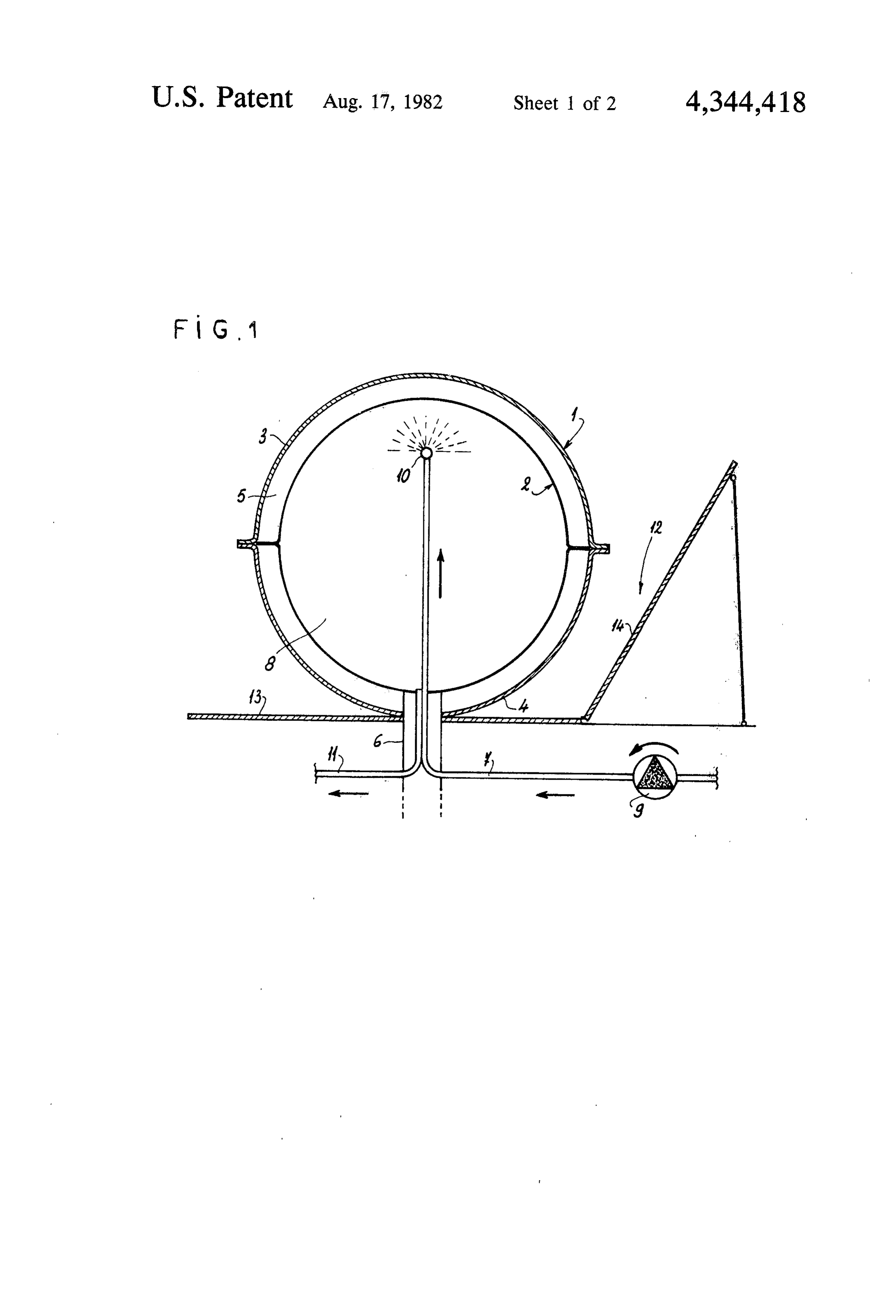
curvature of the lens assembly. The upper portion of the apparatus forms the solar It is known from U.S. Pat. No. 4,136,670 to provide a sphere, collector as such, in the shape of a substantially half solar heating system including an energy absorbent 55 but using integrally the spray principle herein collector dish for receiving solar heat, a supply tube for above stated. The lower portion forms an illuminating distributing a heat transfer fluid over the collector dish, device, the translucent outer sphere playing the role, for a drain pipe for removing the heat transfer liquid from this portion, of a light diffuser. The assembly has the the collector dish and an optical director including an shape larly of a globe, allowing a good integration, particu in an urban environment. The fact that the lower array of converging lenses oriented to receive radiant half alone energy from the sun and to direct the energy onto the is in no wayofathe globe is used for illuminating purposes collector dish. The array of converging lenses com the diffuser of a street lightbecause shortcoming emits the upper portion of usually, towards the prises a matrix of double convex lenses that form one sky, luminous energy which is wasted. On the contrary, half of a hemispherical optical dome, the other half of the separating plane wall situated above the bulb in the which possesses an inner reflective surface for reflect 65 preferred embodiment of the present invention reflect ing radiant energy onto the collector dish and the opti ing, thereby allowing, in the case of the present inven cal dome is oriented such that some portion of the lens tion, a reflecting of additional luminous energy from the array faces the sun during an entire day's movement. bulb towards the ground, this additional energy being 5 usually lost in the atmosphere. It becomes consequently doing, the fluid recovers the heat stored in the space 5 possible to reduce the power of the bulb, hence an im via the sphere 2. The heated fluid is collected at the base portant, desirable economy of energy for lighting can of the inner sphere 2 by the outlet duct 11 which directs be achieved. it towards a place of use or storage. A further remarkable result provided by the just- 5 To the collector thus far described, is associated a mentioned embodiment which forms also a street light, reflector 12 formed of two plane, reflecting surfaces 13 and providing an extra energy saving, resides in the and 14 forming an obtuse angle one with the other. The possibility of recovering the residual heat of the bulb for reflecting surface 13 is placed horizontally on the heating the fluid during the nightime. For recovering ground, below the collector. The other reflecting sur the energy, one has of course to perfect control of the 10 face 14 is inclined and turned towards the South. installation, so as to circulate the heat-carrying fluid The spherical solar collector of simplified structure during the hours of night, the period the bulb supplies a which has just been described is applicable to the eco usable heat. To this end, there can be provided, for nomical production of hot water, notably for the heat example, an extra differential thermostat with a temper ing of swimming pools and the like, and generally to all ature probe placed under the separation wall which is 15 the thermo-solar conversions at low temperature. over the bulb, for controlling a circulation pump for the fluid and heating the latter with the recovered residual in which 2theandsolar
FIGS. 3 illustrate a more particular application collector also forms a street light or heat of the bulb. the like.
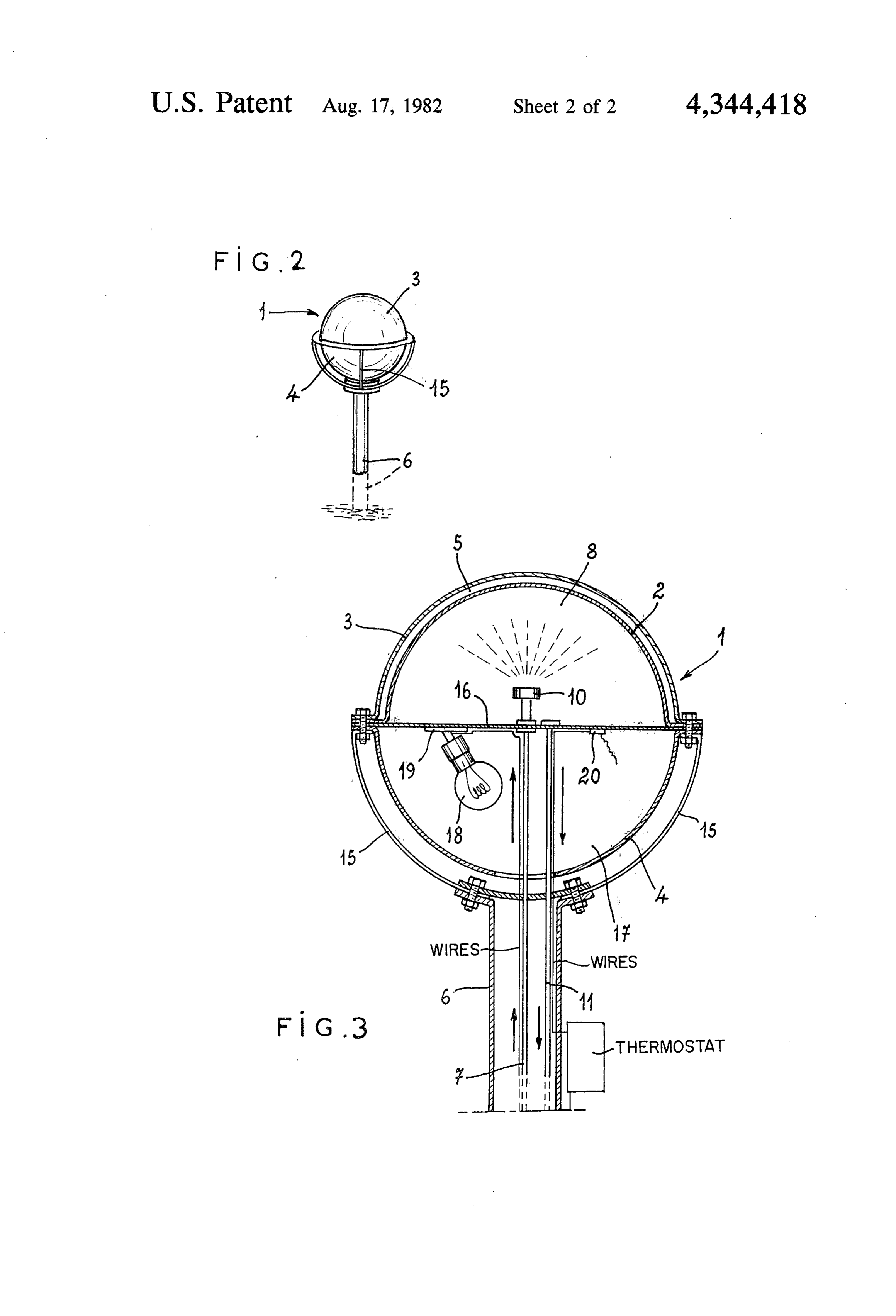
BRIEF DESCRIPTION OF THE DRAWINGS As is shown in FIG. 2, the collector according to the In any case, the invention will become more apparent second embodiment, as seen from the outside, includes from the following description of two embodiments of in this case a vertical support post 6' at the top of which the curved solar collector, namely, a spherical and a is mounted a globe, the visible portion of which is the hemispherical version which are given as non limitative outer sphere 1", formed by the assembly along a hori zontal jointing plane of two hemisphere 3' and 4 made examples, reference being made to the accompanying 25 of a transparent or translucent material such as methac drawings wherein: rylate. The globe formed by these two hemispheres is FIG. 1 is a vertical, sectional view of a first embodi supported by arcuate hoops 15 arranged outside. ment of a solar collector according to the present inven tion; FIG. 3 shows the inner structure of the solar collec FIG. 2 is a perspective, general view of a second 30 tor of FIG. 2, its upper half, being separated from the embodiment of a solar collector according to the pres lower half by a circular plane wall 16. The upper half ent invention, also forming a street light; and forms the solar collector proper, and is made according FIG. 3 is a vertical, sectional view, on a larger scale, to a hemispherical design which can be considered to be constituted in essence by one-half of a spherical design of the collector FIG. 2.
35 of FIG. 1 and to be very similar thereto. Beneath and
DETAILED DESCRIPTION OF THE spaced from the outer hemisphere 3’ made of a translu PREFERRED EMBODIMENTS cent material is the inner sphere 2', concentric to the The solar collector illustrated in FIG. 1 includes two outer hemisphere 3' and separated from the latter by a concentric spheres 1 and 2. The outer sphere 1 is formed space 5' filled with air; the inner hemisphere 2, which by the assembly along a horizontal jointing plane of two 40 has to absorb the solar radiation, is made for example of hemispheres 3 and 4 made of a transparent or translu metal coated with a dull black or other dark color. cent material, for instance a transparent synthetic mate The wall 16 and the inner hemisphere 2' circumscribe rial such as polymethacrylate (known under the trade an inner hemispherical chamber 8' in which is sprayed name of PLEXIGLAS). The inner sphere 2, separated the fluid to be heated. The fluid is conveyed by a duct from the outer sphere 1 by a space 5 filled with air, may 45 7" extending through the support post 6, and extends also be formed by an assembly of two hemispheres; this also vertically through the lower hemisphere 4, as well second sphere 2, which has to absorb the solar radiation, as the wall 16, and is prolongated vertically towards the is made for example of metal coated with a dull black or top inside the chamber 8", and ends in a spray head 10'. other dark color. An outlet duct 11" starting from the lowermost point of The inner sphere 2 is kept inside and centered in the 50 chamber 8', and therefore starting at the level of the outer sphere 1 by a vertical support post 6 which ex upper surface of the wall 16, extends also, vertically, tends through the lower outer hemisphere 4. through the lower hemisphere 4' and the support post An inlet duct 7, conveying to the collector the fluid 6", for collecting the heated fluid and directing it to be heated, penetrates an inner spherical chamber 8 towards a place of use and/or storage. defined by the sphere 2 near its lowermost part by ex- 55 The lower outer hemisphere 4, made of a translucent tending through the support post 6. In the duct 7 is material slightly tinted in white, circumscribes with the inserted a pump 9 situated outside the collector. The horizontal wall 16 another hemispherical chamber 17 duct 7 is vertically prolongated towards the top inside inside which is arranged an electric bulb 18, held for the chamber 8, and the inner end of the duct 7 situated instance by a support 19 fixed the lower surface of the in the upper region of the chamber 8 carries a spray 60 wall 16. The electrical supply of the bulb 18 is provided head 10. by wires (not shown) which extend, of course, through An outlet duct 11 starting from the lowermost point the support post 6". The material of the hemisphere 4.' of the inner chamber 8 extends from the collector under which is housed the bulb 18 is provided with a through the support base 6. ." color and further qualities providing it with the charac The fluid to be heated, for instance water, is sprayed 65 teristics of a good light diffuser. Moreover, the wall 16, into the inner chamber 8, via the head 10. The water is which is situated below the bulb 18, is made reflecting, thus projected firstly against the inner wall of the inner thereby allowing directing back towards the ground the sphere 2 and flows downwardly along this wall; by so luminous energy which the bulb 18 emits upwardly.
Page 6scan →
It is also possible to recover the residual heat of the outer semisphere being permeable to solar radiation, bulb 18, at night, for heating the heat-carrying fluid. To and said inner semisphere being absorbent of the solar this end, there is provided an extra differential thermo radiation; inlet means and outlet means for fluid to be stat for controlling the heat-carrying fluid regulation heated, said inlet means including a duct prolongated pump, not shown, from a temperature probe 20 placed upwardly inside an inner semispherical chamber de under the wall 16 which is over the bulb 18, the installa fined by said inner semisphere; a spray head carried by tion including always and, as is usual, a main differential said duct on its end and capable of projecting fluid to be thermostat controlling the input of solar hot water into heated onto said inner wall surface of said inner semis a stock to be heated, during the day, from a probe mea phere so that the fluid flows while being heated along suring the stock temperature. Commutation between 10 said inner wall surface before being collected at said the "night' thermostat and "day' thermostat is carried outlet means, said outlet means being positioned in a out automatically by means of an electrical time-switch. lowestmost point of said inner semispherical chamber; a If one considers, in the total energy quantity which is substantially horizontal wall extending over the bases of dissipated by an electric bulb, the portion of energy said outer semisphere and said inner semisphere which, which is diffused in luminous form, and when compar 15 with said wall, defines said inner semispherical cham ing it to the quantity of absorbed energy, one sees the ber, in which is sprayed fluid to be heated, in combina interest there would be to recover, as was just described tion with a further semispherical chamber fixed beneath hereabove, the quantity of energy which otherwise said wall and inside which is disposed at least one elec would be lost in the form of residual heat provided by tric light bulb, a support post on top of which is the bulb 8. 20 mounted at some height above the ground said further The solar collector combined with a post and bulb as semispherical chamber through which extends inlet just described with reference to FIGS. 2 and 3 is appli means and said outlet means and also supply wires for cable to the lighting of circulation thoroughfares, road said at least one lightbulb, so as to form a solar collector ways, squares, plots of ground contiguous to buildings combined with a street light.
or industrial premises, parks, swimming pools (for 25 2. A solar collector according to claim 1, wherein which it supplies also the hot water) and the like. In the said outer semisphere and said inner semisphere are a case of an installation which includes several similar respective outer hemisphere and an inner hemisphere. collectors operating in comparable conditions, it is ob 3. A solar collector combined with a street light ac vious that the hereabove mentioned thermostats may be cording to claim 1, wherein said horizontal wall is situ common to the whole installation. 30 ated above said at least one light bulb and is reflecting. It goes without saying that the invention is not lim 4. A spherical solar captor combined with a street ited to the above described and illustrated embodiments lamp, according to claim 1, including a differential ther which are hereabove described by way of example not mostat, with a temperature probe placed under said wall by way of limitation. On the contrary, it encompasses which is above said at least one light bulb for control all alternatives pertaining to the same principle, its 35 ling a fluid circulation pump and heating fluid by recov scope being defined by the appended claims. ering residual heat of said at least one light bulb. What is claimed is: 5. A solar collector combined with a street light ac 1. A solar collector comprising an outer semisphere cording to claim 4, wherein said wall is a planar wall. and an inner semisphere having an inner wall surface, 6. A solar collector combined with a street light ac said outer semisphere and said inner semisphere being cording to claim 1, wherein said wall is a planar wall. concentric with one another and having bases, said as a
Provenance
- Collection
- Patents citing this work
- Pages
- 6
- Method
- pdftotext (the PDF's own text layer) + pdftoppm 300dpi page scans
- Patent office record
- patents.google.com →
- Source
- Google Patents citing-documents table
- Assignee
- Cosmos Investigations And Research Societe Francaise A Responsabilite Limitee
- Published
- 1982-08-17
- Transcribed from
- patentimages.storage.googleapis.com →