

patent · US4346696A
Solar energy collector
31 August 1982
Text
Page 1bibliographic recordscan →
United States Patent (19)
Brunet
54 SOLAR ENERGY COLLECTOR
75 Inventor: Robert Brunet, Eysines, France 73 Assignee: Brunet France S.A., Eysines, France
Foreign Application Priority Data
Sep. 27, 1978 FR France ................................ 78 28310 51 Int. Cl'................................................. F24, 3/O2 52 U.S. C. .................................... 126/450; 126/449;
2,260,638 10/1941 Pfost ............................... 165/149 X
4,003,367 1/1977 Wikholm ............................. 126/434 4,033,325 7/1977 Walker ................................ 126/434
4,078,548 3/1978 Kapany ........................... 126/449 X 4,120,283 10/1978 Eder. a a a a 126/449 X
4,132,222 1/1979 Roark .............................. 126/450 X 4,133,150 1/1979 Yacoboni ........................ 26/450 X 4,136,670 1/1979 Davis ..... ... 126/450 X 4,141,338 2/1979 Lof ...................................... 126/449 4,149,525 4/1979 Prado .................................. 126/450 4,184,480 1/1980 Kenny ................................. 126/450 4,185,616 1/1980 Johnson ..... ... 126/444 X 4,236,507 12/1980 Vincent ............................... 126/450
FOREIGN PATENT DOCUMENTS
OTHER PUBLICATIONS
Article entitled "L'energie solaire a-t-elle un avenir industriel?' by Marcel Perrot et al., (Arts & Metiers,
Primary Examiner-George P. Hall
Attorney, Agent, or Firm-Sandler & Greenblum
A solar energy collector comprising a plurality of three dimensional elements having substantially the same general configuration. Each of the elements has a sub stantially circular base and the elements are nested within one another so as to form the energy collector. 21 Claims, 10 Drawing Figures
Drawings
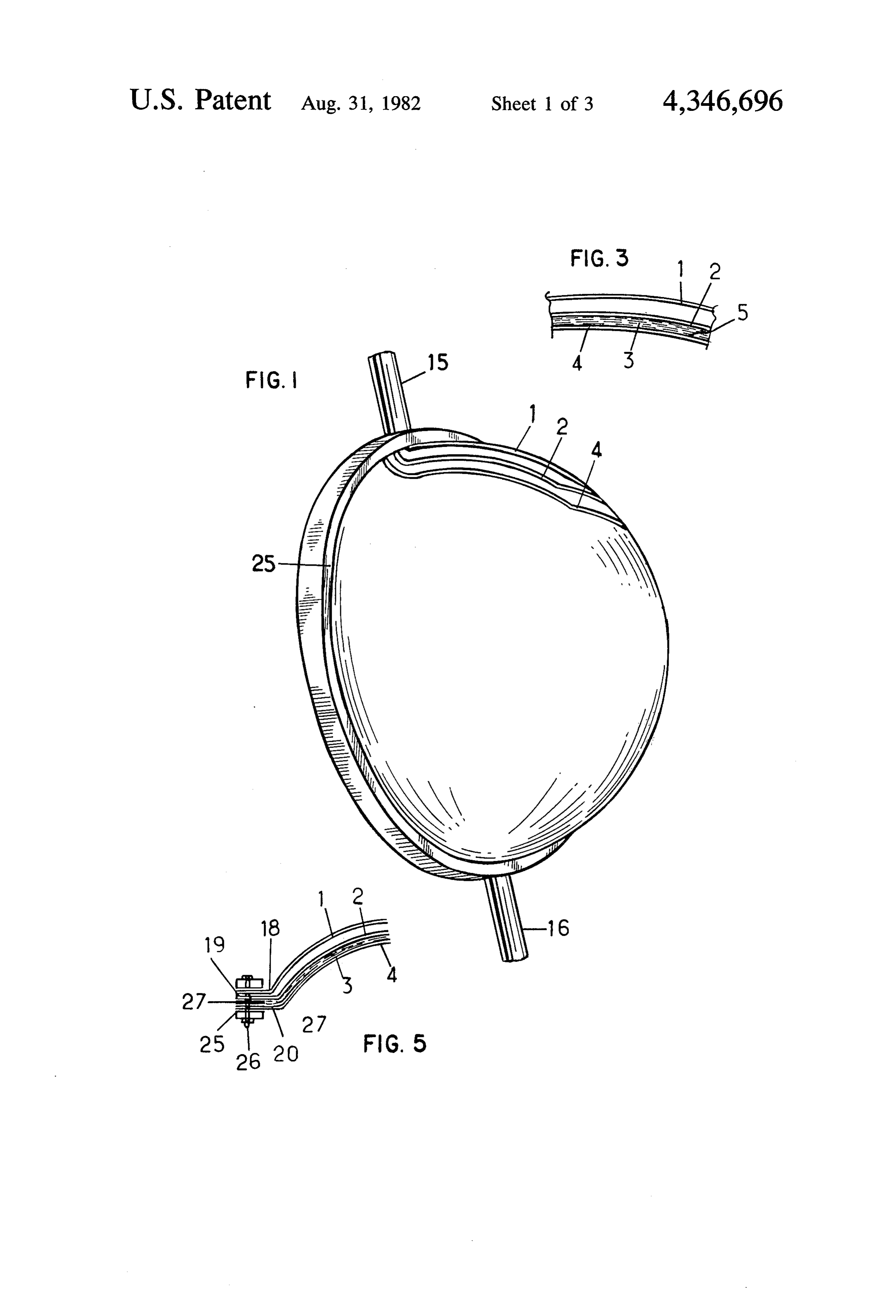
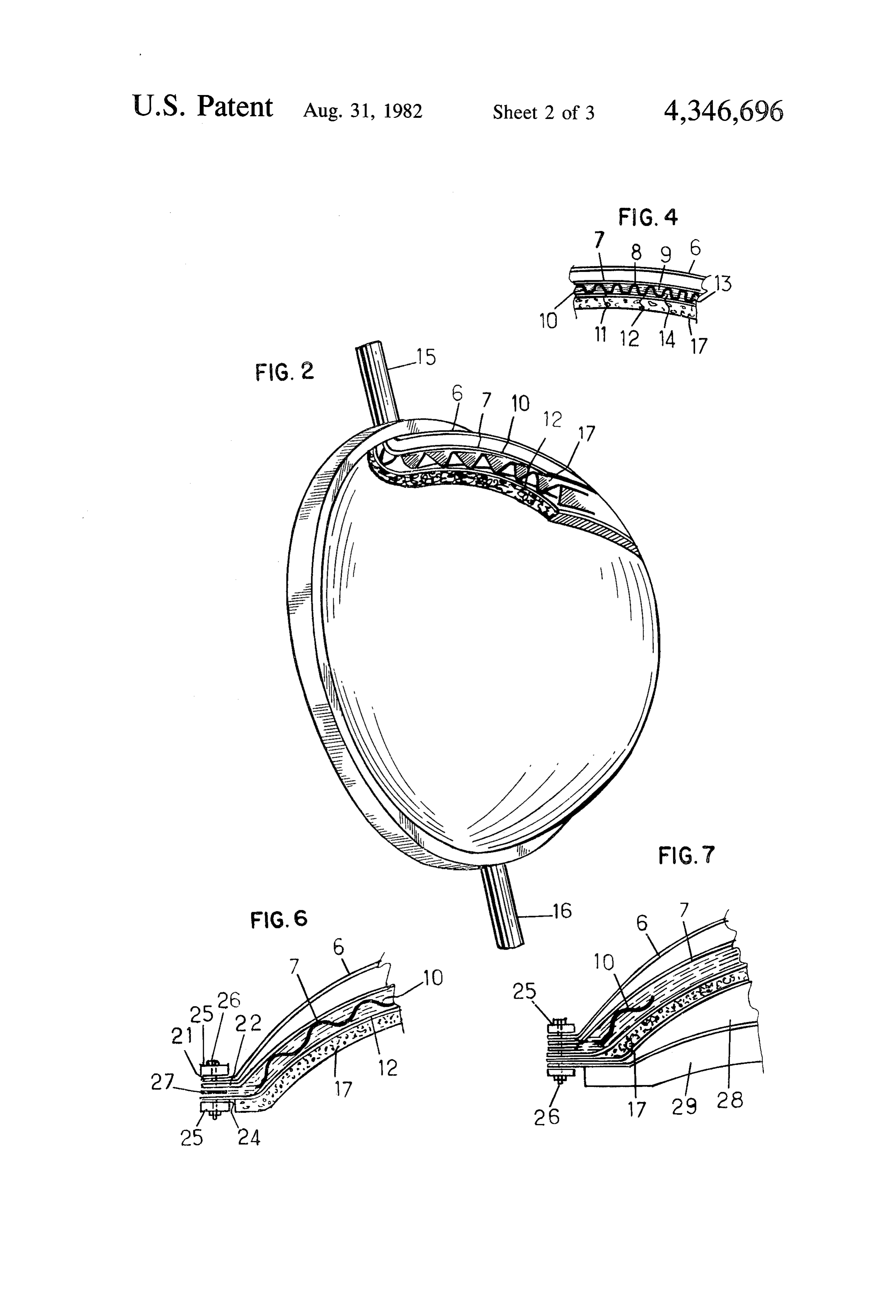
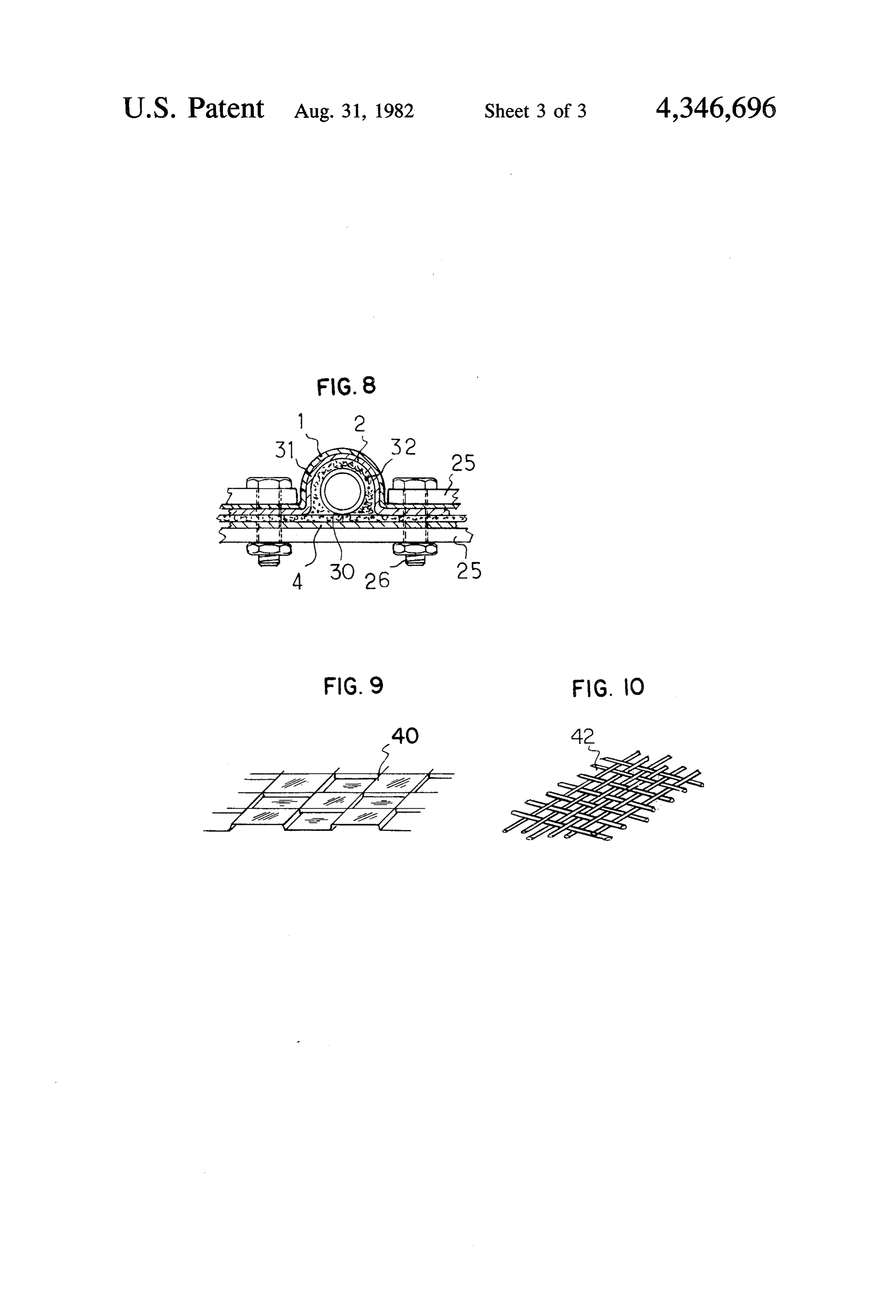
FIG. 6 is a cross-sectional view of the base of the
FIG. 7 illustrates an alternative embodiment of the
Page 2drawing sheetscan →
Page 3drawing sheetscan →
Page 4drawing sheetscan →
Page 5scan →
Solar energy collector
Each of the element has a substantially circular base and the elements are nested within one another so as to form
BACKGROUND OF THE INVENTION the energy collector.
In a preferred embodiment of the invention the ele 1. Field of the Invention ments have the general configuration of a dome. The present invention relates to a solar energy collec In one embodiment of the invention, the collector is tOr.
2. Description of the Prior Art provided with at least three domes: an outer dome, an Various types of solar energy collectors are known. O is transparentandandan isintermediate inner dome, arranged dome. The outer dome so as to yield a green
Principally, known devices comprise a case support whose larger side is open and is arranged so as to face house effect within the collector. the sun. Within the interior of the case a sheet metal The collector may additionally be provided with an aborber is arranged which is either planar or cellular in intermediate dome section under which the heat trans structure and which absorbs solar radiation received fer fluid to be used flows. The intermediate dome may and transmits the heat produced as a result of the radia 15 be in the form of a dome having a plain cross-section, tion through a heat transfer fluid circulating under the i.e., having smoothly arcuate inner and outer surfaces. sheet metal in a reservoir or canal. The reservoir or Alternatively, the dome may be provided with a cellu canal comprises a layer of sheet metal arranged under lar or corrugated cross-section, or stamped into an arcu the absorber sheet metal, in a sealed fashion, preferably ate but irregular configuration. along the entire circumference of the absorber. Thermal 20 Thermal insulation may be arranged beneath the insulation is generally provided beneath the sheet metal inner dome, and the collector may additionally be pro so as to limit thermal losses from the collector. The open face of the case is either left alone or covered with vided with a reservoir arranged between the base of the one or several transparent planar panels. The panels collector and the inner dome so as to provide storage which are planar, but which may also be rounded, serve 25 space for the fluid used as the heat transfer medium. to protect and insulate the absorber while creating a In another embodiment of the invention, the collector greenhouse effect which favors heat transfer to the heat additionally comprises a subdome in addition to the transfer fluid. The collectors are arranged either in a previously recited three domes and the intermediate fixed fashion, or in a rotatable fashion so as to maintain dome is arranged between this subdome and the inner their orientation perpendicular to the sun in the course 30 dome.
of the earth's rotation.
These known solar energy collectors suffer from dome, As yet another feature of the invention, the outer various inconveniences. Principally, it should be noted collarssubdome and inner dome are each provided with at their bases and a belt or strap is provided in that the cost of the prior devices is relatively high be conjunction with these collars for purposes of relieving cause of the materials which must be used, particularly 35 the absorber sheet metal and the reservoir or canal stresses due to expansion and other pressures which which contains the thermal fluid. Furthermore, the occur as a result of exposing the collector to elevated assembly of the prior devices requires that a seal be temperatures resulting from exposure to sunlight. provided over the entire periphery of the device as well BRIEF DESCRIPTION OF THE DRAWINGS as over the various intermediate connections to the 40 device so that deformation resulting from the high tem With respect to the annexed drawings, illustrated by peratures of the thermal transfer fluid do not adversely way of example:
affect the device. FIG. 1 illustrates a perspective view of the inventive Yet another inconvenience of the prior art collectors solar collector comprising three elements having the is that if these collectors are not provided with a device 45 for changing their orientation, a substantial portion of shapewithin of identical three-dimentional domes nested one another;
the rays will be reflected by the transparent closure FIG. 2 is an alternative embodiment comprising five panel and will, as a result, be lost. Naturally, this dimin elements having a dome shape; ishes the yield of the collector. In those cases where the prior art collectors are provided with a transparent 50 FIG. 3 is a cross-sectional view along the vertical axis closure panel having a rounded surface, thus permitting of the collector shown in FIG. 1;
it to capture solar radiation both very early or very late FIG. 4 is a cross-sectional view along the vertical axis in the day, the radiation received cannot be collected of the collector shown in FIG. 2;
and used because the space between the absorber and FIG. 5 is a cross-sectional view of the base of the the rounded section of the closure panel is too great. 55 collector shown in FIG. 1 illustrating the use of a pair of
FIG. 6 is a cross-sectional view of the base of the
It is, therefore, an object of the invention to provide collector illustrated in FIG. 2 further including a pair of a solar collector which is both inexpensive to manufac belts;
ture and yet highly effective. 60
FIG. 7 illustrates an alternative embodiment of the
It is a further object of the invention to provide a invention having a reservoir incorporated therein; solar collector which may be simply sealed while never theless resulting in a high degree of absorption of solar FIG. 8 illustrates the inlet-outlet provided for the radiation. thermal fluid;
These as well as other objects are fulfilled by means 65 FIG. 9 shows one embodiment of the absorber-col of the solar energy collector of the invention which lector for use in FIGS. 1 and 2; and comprises a plurality of three-dimensional elements FIG. 10 illustrates one embodiment of an intermedi having substantially the same general configuration. ate dome which may be used in the device of FIG. 2.
Page 6scan →
DESCRIPTION OF PREFERRED As shown in FIGS. 2 and 4, the collector may corn. EMBODMENTS prise four elements nested within one another, each of the elements comprising substantially identical domes,
The solar energy collector according to the invention each having a circular base. The outer dome 6 is trans comprises at least three elements nested within each parent and is oriented to face the sun. This outer dome other. Each of the elements has a substantially identical constitutes a protection wall and is spaced from the wall shape and is a three-dimensional dome having a circular of first subdome 7 which is itself transparent. Domes 6 base. Provided are: a transparent outer dome which and 7 may be made of reinforced plastic material, ther serves to provide a greenhouse type effect, an interme moset plastic, glass or glass products and the like. The diate dome, and an inner dome. The intermediate dome 10 first subdome 7 is supported on its inner surface by the which is offset from the outer dome may be either pla upper extremity 8 of the corrugations or cells 9 of the nar, cellular, corrugated or pressed into any other form. intermediate dome 10. As shown, the intermediate This intermediate dome acts as the absorber or collec dome has a generally sinusoidal configuration. The tor, and the heat transfer fluid used to transfer thermal lower portions 11 of the corrugations or cells 9 are energy from the collector circulates under the absorber 15 supported by inner dome 12 whose outer surface 13 is or collector, between the collector and the inner dome. reflective. As was the case with dome 4, dome 12 may The third element of the solar energy collector is the be made of reinforced plastic material, ferrous or non inner dome whose outer face, i.e., the face of the dome ferrous metal, concrete, cement, or the like. Intermedi directed towards the outer dome, is in contact with the ate dome 10 acts as an absorber or collector as was thermal fluid and is constructed so as to reflect radia 20 previously described with respect to the first embodi tion. Each of the elements of the collector is connected ment, and acts to absorb ultra-violet rays produced by at its periphery by means of a belt or pair of belts which the sun and to transmit infrared rays which are reflected relieves the effects of expansion and of pressure to by the outer reflective surface 13 of the inner dome 12 which the domes are subjected in the course of their as well as by a portion of domes 6 and 7 so that these exposure to full sunlight. 25 rays are transfererred to the heat transfer fluid 14 circu Turning to the drawings, FIGS. 1 and 3 illustrates lating and streaming between the first subdome 7 and two embodiments of the invention in which the solar the inner dome 12 over the corrugations or cells 9. collector has at least three elements nested within one Dome 10 may be made of reinforced plastic material, another, each of these elements having the shape of a thermoset plastic, ferrous or non-ferrous metals formed three-dimensional dome with a circular base and a col 30 in flat or arcuate sheets which may be nested if desired. lar. Outer dome i is transparent and is normally ori Dome 10 may further be in the form of a ferrous or ented so as to face the sun. This dome further acts as a non-ferrous metal screen or network of interwoven protection barrier or wall for the solar energy collector. wires so as to provide a surface having interstices Outer dome 1 may be made of reinforced plastic mate through which the thermal fluid is free to pass as it rial, thermoset plastic, glass or glass products, or the 35 circulates. The fluid is fed into the collector by means of like. Outer dome 1 is spaced from intermediate dome 2 an inlet 15 and leaves through an outlet 16, although the which may be either planar, corrugated, or celled in inlets and outlets are reversible and the fluid may obvi cross-section. Dome 2 may be made of reinforced plas ously flow in the opposite direction (FIG. 8). The solar tic material, thermoset plastic material, ferrous or non energy collector may constitute part of an energy cir ferrous metal or the like in sheets or arcuate sheets 40 cuit in which heat transfer fluid leaves the collector and which may be nested. Intermediate dome 2 acts as an is brought into contact, by means of a heat exchanger, absorber or collector for the ultra-violet rays emitted by with another fluid or substance adapted to receive calo the sun which it serves to transform and transmit, in the ries of heat from the heat transfer fluid. Once having form of infra-red radiation to the heat transfer fluid 3, given off its excess heat, the heat transfer fluid may then circulating under the intermediate dome 2. The thermal 45 be returned to the inlet of the collector to be heated transfer fluid circulates between intermediate dome 2 once again. As previously described, besides acting as a and outer reflective face 5 of inner dome 4. Inner dome protector, outer dome 6 makes it possible to create a 4 may be made of reinforced plastic material, ferrous or greenhouse type effect within the collector. A thermal non-ferrous metal, concrete, cement or the like. Besides insulator 17 may be applied under the dome 12. The acting to protect the solar energy collector, outer dome 50 thermal insulation may be provided with sufficient body 1 also functions to create a greenhouse effect thus in so as to maintain itself in position or it may be main creasing the heat transferred to the absorber and/or tained by means of a skeleton support structure not collector. This outer dome additionally reflects a por shown.
tion of the infrared and ultraviolet rays which it trans As shown in FIGS. 5 and 6, domes 1, 2, 4, and 6, 7, 12 mits to the absorber and/or collector. 55 each end in a small collar or rim 18, 19, 20, and 21, 22, As shown in FIGS. 4 and 6, a layer of insulation 17 24 respectively. These collars make it possible to assem may be applied against the inner surface of the inner ble and maintain the domes in their proper orientation dome so as to avoid and minimize heat losses. by means of a circular belt or pair of belts 25 arranged The heat transfer fluid is circulated throughout the above and below the superimposed collars. The belt 25, solar collector and passes through an inlet 15 before 60 which may be made of metal, is resistant to the effects of transversing the solar collector and escaping through expansion and of pressure to which the domes are sub outlet 16. By connecting the inlet and outlet of the solar jected when placed in full sunlight and serves to over energy collector with a line comprising a suitable heat come the expansion absorbed by the domes themselves exchanger, the heat absorbed by the heat transfer fluid which may become deformed without causing deterio may be transferred to another medium by means of the 65 ration of the solar energy collector or its operation. The heat exchanger. Thus the calories of energy absorbed belt 25 is secured to the solar energy collector by means by the heat transfer fluid may be transferred to the fluid of nuts and bolts 26 although other means of securing or substance where they are ultimately needed. the belt may obviously be used. However, so as to cre 7 ate a perfect seal between the domes 2 and 4, and 7 and metallic, ferrous or non-ferrous, plastic or glass wires or 12, a seal 27 may be arranged between each of the col threads.
lars (although only one such seal is shown) so as to The invention has been described with respect to prevent the heat transfer fluid from leaking out of the specific means and materials. It is to be understood, solar energy collector structure. however, that the invention is to be construed as limited With reference to FIG. 6, intermediate dome 10 is not only by the claims.
provided with a collar. Instead, this dome is arranged What is claimed is:
and maintained between domes 7 and 12 so as to allow 1. A solar energy collector comprising at least four for the free expansion of this dome without such expan domes:
sion resulting in possible leakage of the thermal fluid 10 result inana outer transparent dome arranged so as to greenhouse effect within said collector, a around the circumference of the belt 25 at the level of the joints formed with securing means 26. Such an ar each of said domes having and subdome, an inner dome, an intermediate dome;
rangement, due to the free unsecured end of dome 10, and being nested within one another so as circular a substantially to form base said further leads to the division of the thermal fluid into two streams which flow over both sides of the interme 15 energy collector, each of said domes having a collar at diate dome3. 10 between domes 7 and 12. The intermedi its base, said collars overlapping when said domes are ate dome is thus arranged to permit the thermal fluid to nested, said collector further comprising a belt arranged above and below said collars so as to absorb stresses to flow freely, from the inlet to the outlet of the collector. which each of said domes is subjected. According to the embodiment shown in FIG. 7, the 2. The solar energy collector as defined by claim 1 space between the insulation 17 and the base of the 20 wherein said inner dome has an outer surface which is collector may be adapted to include a reservoir 28 con reflective to infrared radiation. taining the liquid, fluid, or other substance to be heated 3. The solar energy collector as defined by claim 2 by the heat transfer fluid. This is done by passing pipes wherein said intermediate dome has a hemispherical and lines (not shown) comprising a heat exchanger into contact with the reservoir. The heat transfer fluid flows 25 cross-section and said intermediate dome is adapted to through the heat exchanger and heats the liquid within provide a passage for the flow of a fluid under said the reservoir 28. Quite obviously, reservoir 28 as well as intermediate dome between said outer and inner domes, all exterior lines and pipes may be insulated so as to and said intermediate dome is adapted to act as a collec avoid and minimize heat losses. The reservoir 28 may be tor of infrared radiation and is adapted to transfer said provided with stiffeners 29 so as to withstand possible 30 radiation to said fluid.
deformations resulting from thermal shocks or strong 4. The solar energy collector as defined by claim 3 localized pressure differences. The reservoir 28 may wherein said intermediate dome is planar in cross-sec tion.
comprise two domelike structures having a space be tween them wherein the material to be heated is stored. 5. The solar energy collector as defined by claim 3 Each of the domelike structures may themselves end in 35 wherein said intermediate dome is cellular in cross-sec a collar located at the base of the energy collector. tion.
The reservoir is positioned between the inner dome 6. The solar energy collector as defined by claim 3 and the collector base; the inner dome and collector wherein said intermediate dome is corrugated in cross base together define a volume which does not extend section.
outwardly beyond the base of the inner dome, as shown 40 7. The solar energy collector as defined by claim 3 in FIGS. 1-7. The fluid reservoir is located within this wherein said intermediate dome is stamped so as to volume, between the collector base and the inner dome, result in an irregular but arcuate configuration. irrespective of the shape of the collector base. 8. The solar energy collector as defined by claim 1 As seen from FIG. 8, the solar energy collector com wherein said subdome is inwardly spaced from said prises a structure which may serve as inlet 15 as well as 45 outer dome and outwardly spaced from said inner outlet 16 for the thermal fluid. The structure comprises dome.
a pipe or tube 30 which extends from the exterior of the 9. The solar energy collector as defined by claim 8 solar collector to within the device such that the pipe is wherein said intermediate dome is adapted to collect in fluid communication with the spaces between domes infrared radiation and to transmit said radiation to fluid 2 and 4, or 7 and 12 depending upon the type of solar 50 circulating between said intermediate dome and said collector structure being used. The pipe or tube extends inner dome.
through an expanded portion 31 of collars 18 and 19 or 10. The solar energy collector as defined in claim 9 21 and 22. The expanded portion 31 has a shape which wherein said intermediate dome is arcuate in cross-sec corresponds to that of the tube or pipe and itself acts as tion.
a collar. An effective fluid seal is assured by virtue of a 55 11. The solar energy collector as defined by claim 9 packed joint 32. The sealing joint is compressed when wherein said intermediate dome is cellular in cross-sec the holding means for the belt such as nuts and bolts 26 tion.
are tightened. This tightening results in the tube or pipe 12. The solar energy collector as defined by claim 9 becoming immobilized within the collar 31. The tube or wherein said intermediate dome is corrugated in cross pipe extends no further than the space between the 60 section.
domes. 13. The solar energy collector as defined by claim 9, FIG. 9 illustrates a celled structure 40 for use as an wherein said intermediate dome is stamped so as to intermediate dome suitable for use in conjunction with result in an irregular but arcuate configuration. the solar collectors illustrated in either FIG. 1 or 2 as 14. The solar energy collector as defined by claim the intermediate dome 2 or 10. 65 further comprising a layer of thermal insulation beneath FIG. 10 illustrates an alternative material structure 42 said inner layer.
for use as the intermediate dome 10 in the embodiment 15. The solar energy collector as defined by claim 14 of FIG. 2. The material comprises a screen or weave of further comprising a fluid reservoir for heat transfer 8 fluid arranged between said thermal insulation and the dome and the base of said solar energy collector and base of said solar energy collector. which is located within said volume. 16. The solar energy collector as defined by claim 15 19. The solar energy collector as defined by claim 18 wherein said heat transfer fluid reservoir comprises two 5 wherein said heat transfer fluid reservoir comprises two domelike structures with a space between them, each of domelike structures with a space between them, each of said said domelike structures ending in a collar arranged at at thetwo domelike structures ending in a collar located base of said energy collector.
the base of said energy collector. 20. The solar energy collector as defined by claim 18 17. A solar energy collector as defined by claim 1 further comprising a layer of thermal insulation posi wherein said intermediate dome is arcuate and has a 10 tioned between said inner dome and said fluid reservoir. generally sinusoidal configuration. 21. A solar energy collector comprising a base and at 18. A solar energy collector comprising a base and least three three-dimensional elements having substan four three-dimensional elements having substantially tially the same general configuration, each of said ele ments comprising a dome having a substantially circular the same general configuration, each of said elements 15 base, comprising a dome having a substantially circular base, to form said domes being nested within one another so as said domes being nested within one another so as to comprising said energy collector, said at least three domes an outer, transparent dome which is adapted form said energy collector, said domes comprising an to cause a greenhouse effect within said solar collector, outer transparent dome which is adapted to cause a an intermediate dome adapted to collect infrared radia greenhouse effect within said solar collector, a sub 20 tion and to transmit said radiation to fluid circulating dome, an intermediate dome which is adapted to collect between the intermediate dome and an inner dome, said infrared radiation and to transmit said radiation to fluid inner dome being adapted to reflect infrared radiation, circulating in the space between said subdome and an said inner dome and said collector base together defin inner dome, said inner dome being adapted to reflect 25 theing a volume which does not extend outwardly beyond infrared radiation, said inner dome and said collector further base of said inner dome, said solar energy collector base together defining a volume which does not extend is arranged comprising a heat transfer fluid reservoir which between said inner dome and the base of said outwardly beyond the base of said inner dome, said solar energy collector and which is located within said solar energy collector further comprising a heat transfer volume.
fluid reservoir which is arranged between said inner 30 k k k :k
Provenance
- Collection
- Patents citing this work
- Pages
- 8
- Method
- pdftotext (the PDF's own text layer) + pdftoppm 300dpi page scans
- Patent office record
- patents.google.com →
- Source
- Google Patents citing-documents table
- Assignee
- Brunet France S.A.
- Published
- 1982-08-31
- Transcribed from
- patentimages.storage.googleapis.com →