

patent · US4343297A
Solar energy collector
10 August 1982
Text
Page 1scan →
United States Patent (19)
Figge
54 solar energy collector
76 Inventor: Irving E. Figge, 11209 Susan Dr.,
Sandy, Utah 84070
Related U.S. Application Data 63 Continuation-in-part of Ser. No. 45,918, Aug. 17, 1979, abandoned.
is sess as a as a so so a ea a a 8 e s to 8 w1367a, (52) V. V. ................................." s 126/445 58) Field of Search ................................ 126/428-432,
4,007,728 2/1977 Guba ................................... 126/449 4,076,015 2/1978 Mattson ............................... 126/449 4,077,393 3/1978 Mattson ...... . . 126/449 4,078,548 3/1978 Kapany ...... ... 126/ i. 2. Super 3%3. 4iii. 1869/1978 Rg - - - - - -- 126/449 4121565 16/1978 Grisbrook. . . 126/449 4,126,270 1 1/1978 Hummel ..... ... 126/428 4,141,338 2/1979 Lof ...................................... 126/449
4,178,911 12/1979 Mattson ............................... 126/449 4,204,521 5/1980 Mattson ..... ... 126/446 4,210,128 7/1980 Mattson. ... 126/444 4,239,032 12/1980 Irving .................................. 126/450
Foreign patent documents
2282092 3/1976 France ................................ 126/449 55-46375 4/1980 Japan .................................. 126/449
Other publications
Source of Energy',y Feb., 1974,y No. 13, p.
Primary Examiner-James C. Yeung
Attorney, Agent, or Firm-Fidelman, Wolffe & Waldron
A solar energy collector has, as its basic component, a Alter which are RE"shapes, modified polyhedral E. totheincrease pocketsexof posed surface and heat transfer areas. This panel, having various polyhedral pockets in combination with glazing and a back cover, provides an overall, structurally sound collector which may have degrees of curvature ranging from flat to compound to spherical. A through window ventilation receptacle may be used to support the collector, and may also serve as a plenum, if desired, to facilitate intake and distribution of room air.
4. Claims, 6 Drawing Figures
Drawings
Page 2drawing sheetscan →
Page 3drawing sheetscan →
Page 4scan →
ometry necessary to produce the desired curvature can
SOLAR ENERGY COLLECTOR be determined analytically. This collector structure provides increased compressive strengths and increased
This application is a continuation-in-part of pending flexure stiffness.
application U.S. Ser. No. 45,918, filed Aug. 17, 1979, Structural efficiency is derived from joining the bases abandoned. of the polyhedral pockets of greatest depth to a (prefer BACKGROUND OF THE INVENTION ably insulated) back cover to produce a sandwich struc ture in which the pocketed collector panel serves as an
The basic constituents of any solar energy collector integral core, as well as a partial face sheet. By design, include a collector element, glazing, and an enclosure 10 the collector panel also serves as the collector closure frame (preferably insulated), to support the glazing and (sides, top, bottom) and as a frame for the glazing. The the collector element. The ability of a solar collector to sides and top of the collector panel also are designed to collect solar energy is a function of the collector ele present themselves to the sun's rays, thus acting as an ment surface area and the orientation of the collector uninsulated, unglazed collector member. The sides, top, surfaces relative to the incident angles of the sun. The 15 and glazing framework are an integral part of the col ability of a solar collector to transfer the collected en lector panel and can be fabricated in a single operation, ergy to the desired media (air, liquid, etc.) is a function thus lending to low cost, automated, mass production. of the collector element surface area and the distance Additionally, the design and placement of the core the media travels over the collector element. Heat polyhedra is such that they provide, in combination losses are a function of the type and number of glazing 20 with the back member, a natural path (ductwork) for utilized and the insulation capacity of the frame enclo the transfer medium (air). Thus, little or no additional sure. Cost effectiveness of the collector is a function of ductwork is required. The design of the collector is the effective use of low cost materials and designs such that the flow path of the media starts at the top of which lend themselves to automated mass production. the collector (between the unexposed surface of the Numerous solar collector designs have evolved over 25 collector and the back cover) and proceeds to and the years. However, none of these designs have at through holes in the bottom of the collector element. tempted to optimize all of the above mentioned parame The medium then flows upward between the glazing ters in a single solar energy collector concept. and the front exposed face of the collector. Since the Accordingly, it is an object of this invention to opti medium flows over both the unexposed surface and mize all of the above mentioned parameters in a single 30 exposed surface of the pocketed collector panel, the solar energy collector. The concept of a structural core effective heat transfer area is greater than that of a flat as in U.S. Pat. No. 3,645,833 (filed May 20, 1970 and panel. As such, the design provides excellent heat trans issued Feb. 29, 1972) gave direction of the structural fer to the medium and minimizes the need for insulation. core of U.S. application Ser. No. 45,918 (filed Aug. 17, Venting of the heated medium to the room or area to 1979) which in turn, evolved into the invention of the 35 be heated is accomplished by a simple external vent instant application. housing which must include inlet and outlet ports (with The instant invention comprises a solar energy col or without directable louvers) attached to holes in the lector employing a unique collector panel which, be back cover of the collector and a circulation device sides serving as an efficient solar collector, also serves (such as a fan or pump). Any material or design can be as: the basic structural member of the collector provid used for the vent so long as it is compatable with the ing inherent structural integrity; the frame for single or inlet/outlet ports in the collector. multiple glazing; a portion of the integral ductwork for Since the collector panel and attached back cover the transfer media. provides a high degree of structural efficiency, the col The energy collector panel comprises a plurality of lector is self supporting and may be used as a mounting collector pockets in the form of concave, tapered, trun 45 unit for through-window, through-wall, and the like cated, three dimensional polyhedra. These pockets of installation.
three dimensional polyhedra provide numerous exposed In one preferred embodiment of the invention, each surfaces which are oriented at various angles relative to solar energy collector pocket is a minor variation of a the path and azimuth of the sun as it sweeps its arc tetrahedron, more preferably a truncated tetrahedron. across the sky. Thus, there are always some surfaces 50 It is a documented fact that a tetrahedron has the high favorably inclined relative to the rays of the sun. The est surface area to volume ratio of any known regular relative positioning of the pockets is such that, as one three dimensional shape. The pocketed collector panel internal surface of a polyhedra begins to become increases the surface area presented to the sun by a shaded, a neighboring surface begins to receive sun factor of at least 2.5 over a flat plate panel, thus provid light. Due to this structure, positioning of the collector 55 ing a highly efficient, exposed shape for solar energy relative to the sun is not critical. It is also contemplated collection.
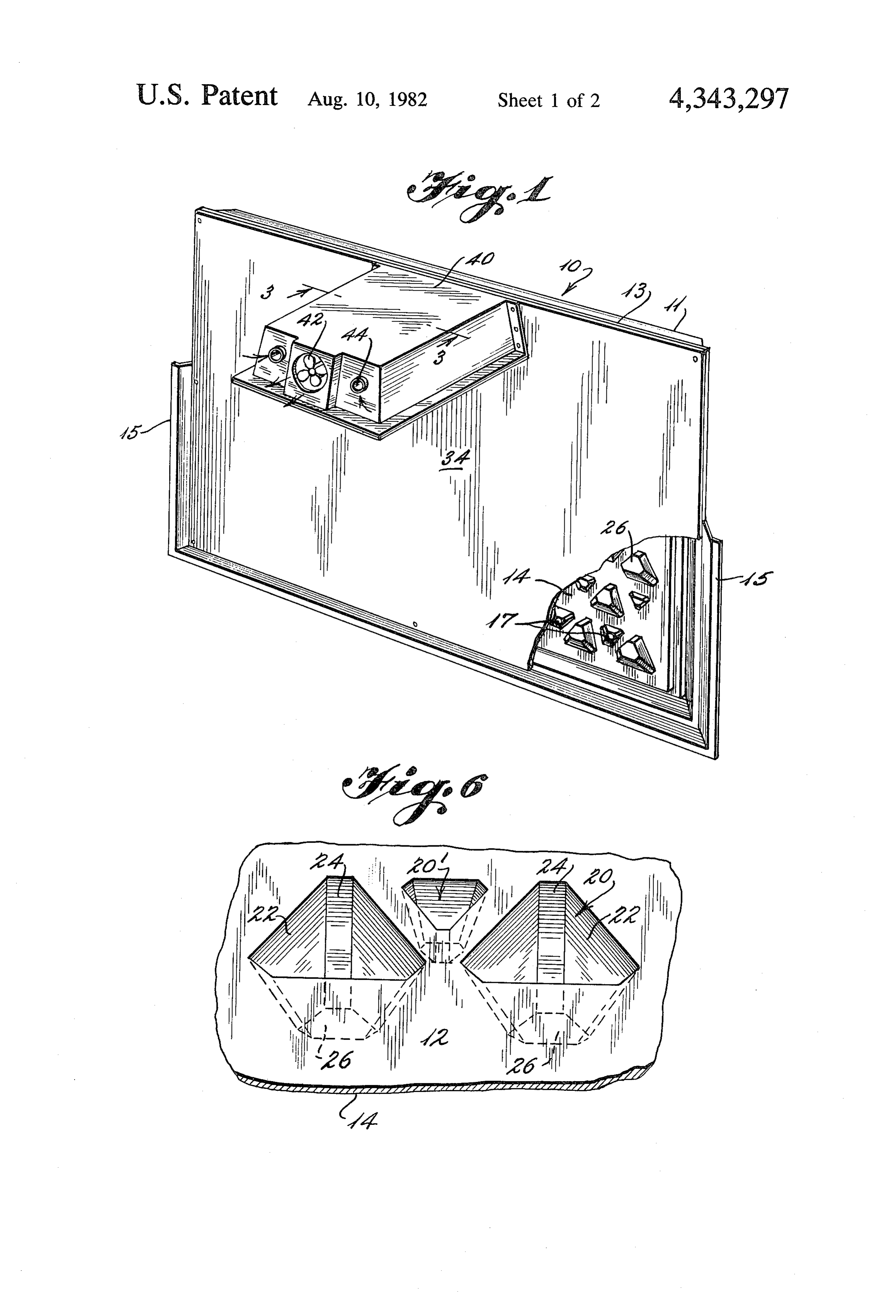
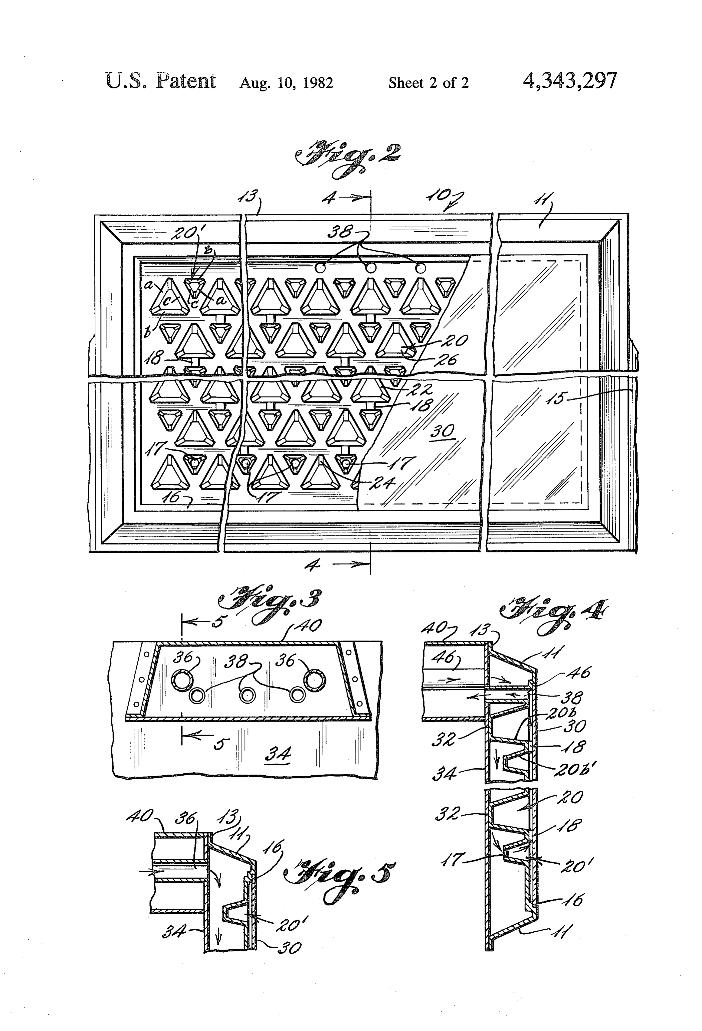
that each pocket may be in the form of a cone or trun cated cone. BRIEF DESCRIPTION OF THE DRAWINGS The solar energy collector panel can be made from FIG. 1 is a rear isometric view of the collector with any of the moldable materials including, but not limited 60 the back cover partially cut away to show the unex to, plastics, metals, wood products, and composites. posed surface of the pocketed panel.
The pockets of the panel may be identical in size and FIG. 2 is a front view of the device of FIG. 1, with shape or may be any combination of various sizes and the glazing partially cut away to show the exposed shapes of polyhedra. By incorporating regularly or surface of the pocketed collector panel. irregularly placed polyhedral pockets of various sizes 65 FIG. 3 is a sectional view along the lines 3-3 of FIG. and/or shapes into the collector, different degrees of 1.
curvature may be accomplished. This curvature may FIG. 4 is a fragmentary sectional view along the lines range from flat to compound to spherical, and the ge 4-4 of FIG. 2.
Page 5scan →
FIG. 5 is a partial sectional view along the lines 5-5 44, and tubing (such as that indicated as 46 in FIG. 4) to Of FIG. 3. connect the exhaust 42 or the intakes 44 to their respec FIG. 6 is an enlarged, fragmentary view of the ex tive outlets ports 38 and inlets ports 36. Of course, ex posed surface of the collector panel, showing several of haust 42 and intakes 44 may be arranged in a different the pockets. 5 configuration and may include adjustable louvers in DETAILED DESCRIPTION OF ONE order to segregate and direct the air flow. The advan EMBODIMENT OF THE INVENTION tage of a ventilation receptacle 40 is that the collector may be positioned on the outside of a building while
FIGS. 1 and 2 depict the overall structure of the having the collector receptacle 40 extend through a energy collector. The side of the solar collector that is 10 window opening or the like to the interior of the build exposed to the sun is shown in FIG. 2. Referring to ing, thus providing a ventilation interconnection be FIG. 2, the basic collector panel 10 includes a plurality tween the exterior and interior of the building as well as of molded, plastic, truncated tetrahedral pockets 20 a means of support for the collector.
interspersed with smaller pockets 20 of the same gen As indicated by the airflow arrows (seen in FIGS. 1, eral structure. As may be seen in FIG. 6, each of these 15 and 5), air is sucked into intakes 44 and inlet ports 36 to pockets 20 and 20' are generally tetrahedral-shaped flow downwardly between back cover 34 and the unex recesses. These modified tetrahedral pockets 20 and 20 posed surface 14 of the collector panel 10. The smaller include faces 22, quasi-faces (truncated edges of a tetra pockets 20' obviously enhance airflow across the unex hedron) 24 and a base (truncated vertex of a tetrahe posed surface 14 of panel 10. Near the bottom of panel dron) 26 opening toward the exposed surface 12, with 20 10, crossover holes 17 allow the air to circulate through the bottom side of each pocket protruding outwardly panel 10 to the space between the exposed surface 12 of from the unexposed surface 14 of the panel 10. As may panel 10 and the glazing 30. As stated earlier, various be seen from FIGS. 4 and 6 pockets 20 and 20' are spacers 18 aid in the support and spacing of glazing 30 substantially similar in shape, with pocket 20' being from exposed surface 12. Having circulated through smaller than pocket 20 in all dimensions. For purposes 25 crossover holes 17, the air then passes over the exposed of describing the relative orientations of the pockets of surface 12 as it circulates to the outlet ports 38 and the panel 10, pocket 20 may be considered as rotated 180 exhaust fan 42.
degrees about a normal to exposed surface 12 and rela Of course, means of circulation other than a fan in tive to pocket 20', such that face 20A corresponds to cluding naturally occurring thermal convection, could face 20A of substantially similar pocket 20'. Likewise, 30 be utilized with the solar collector. In addition, a ther faces 20B and 20O correspond respectively to faces mostat control could be incorporated into the device. 20B and 20'C. Although the structural stength of the The exposed surface 12 of panel 10 may be coated panel is increased when more of the pockets are of the with a black matte finish to enhance absorption of the same depth (to provide an increased number of support heat from the sun. In addition, the glazing 30 may be points for back cover 34), the interspersing of pockets 35 tinted as deemed appropriate for use. Back cover 34 20 and 20' has been found to provided adequate struc could be insulated; however, it is preferable that sides tural support while, at the same time, limiting the points 11 have a black matte finish and are not insulated of contact of the collector panel 10 and back cover 34 to thereby increasing the collection of incident solar en decrease heat loss. Additionally, with pockets 21' of ergy.
smaller depth, less of an obstruction to airflow is pres 40 Thus it will be seen that the objects set forth above, ented. among those made apparent from the preceding de Referring to FIGS. 2 and 4, a transparent or translu scription, are efficiently attained and, since certain cent glazing 30 is mounted in an integrally molded inset changes may be made in the construction set forth with step 16 of panel 10. Various spacers 18 are attached to out departing from the scope of the invention, it is in the exposed surface 12 of panel 10 and engage the inside 45 tended that all matter contained in the above descrip of glazing 30 for support, while allowing spacing of tion and as shown in the accompanying drawings shall glazing 30 from exposed surface 12. be interpreted as illustrative and not in a limiting sense. Panel 10 also includes sides 11 and the flanges 13 It is also to be understood that the following claims assisting in the support and positioning of a back cover are intended to cover all of the generic and specific 34. Additionally, flanges 13 are extended further toward 50 features of the invention herein described, and all state the rear as at 15 for mounting or spacing purposes with ments of the scope of the invention, which, as a matter respect to the side of a building or the like. of language, might be said to fall therebetween. Referring to FIGS. 4 and 5, back cover 34 includes Now that the invention has been described, what is inlet ports 36 and outlet ports 38, and crossover holes 17 claimed as new and desired to be secured by Letters are located in the base of the bottom row of small pock 55 Patent is:
ets 20' of the collector panel 10. Of course, these cross 1. A solar energy collector having a front, a back, and over holes 17 could be located elsewhere in the panel, sides, and comprising:
such as through the faces or quasi-faces of the large or a thin-walled energy collector panel comprising plu small pockets. ral alternately interspersed small and large gener Also referring to FIG. 4, it may be seen that the back 60 ally tetrahedronal-shaped collector pockets formed cover 34 is attachable to the bases of the larger pockets therein, an exposed surface facing said front and 20, as at 32, to lend overall structural support and integ exposable to the sun and an unexposed surface rity to the collector. facing said back, each of said pockets opening Additionally, the solar collector includes a means of toward said exposed surface and having a trun circulation of the active medium (such as air). This 65 cated closed base, and a substantially perpendicu embodiment of the invention discloses a ventilation lar depth from said exposable surface to said base, receptable 40 attached to the back cover 34 of the col the depth of said small pockets being less than the lector, and includes an exhaust fan 42, air intake ports depth of said large pockets;
Page 6scan →
a glazing sealingly attached to and closing said front; first pocket is oriented about said substantially normal a back cover sealingly attached to and closing said direction relative to said second pocket such that at back and engaged by at least some of said large least one of said faces of said first pocket is not parallel pocket bases such that said large pockets provide to rays of the sun when the corresponding face of said internal structural support to said collector; second pocket is parallel to said rays of the sun. inlet means for entrance of air to and outlet means for 3. An apparatus as in claim 1, wherein said circulation exit of air from said collector; and means includes an air pump.
circulation means for circulation of air along a flow 4. A solar energy collector as in claim3, wherein said path from said inlet means to said outlet means. circulation means further includes an attached ventila 2. A solar energy collector as in claim 1 wherein at 10 tion receptacle extendable through a building wall to least a first and a second of said pockets open toward support said apparatus and to provide air circulation said exposed surface in a direction substantially normal between the interior of the building and the collector to said exposed surface and are substantially similar in panel.
shape to provide corresponding faces and wherein said sk k :
Provenance
- Collection
- Patents citing this work
- Pages
- 6
- Method
- pdftotext (the PDF's own text layer) + pdftoppm 300dpi page scans
- Patent office record
- patents.google.com →
- Source
- Google Patents citing-documents table
- Assignee
- Figge Irving E
- Published
- 1982-08-10
- Transcribed from
- patentimages.storage.googleapis.com →