

patent · US4373996A
Apparatus for producing fresh water from sea water
15 February 1983
Text
Page 1bibliographic recordscan →
United States Patent (19)
Maruko
54 APPARATUS FOR PRODUCING FRESH
WATER FROM SEA WATER
76 Inventor: Saburo Maruko, 430-3 Kamiwada,
Yamato-Shi, Kanagawa-Ken, Japan
(30) Foreign Application Priority Data
Mar. 4, 1980 JP Japan .................................. 55-26104
52 U.S.C. .................................... 202/173; 202/174;
2,490,659 12/1949 Snyder ................................ 202/174
3,394,054 7/1968 Hoham ................................ 202/234
4,270,981 6/1981 Stark ........ ... 203/DIG. 1 4,273,102 6/1981 Anthony ............................. 126/435
4,285,389 8/1981 Horton ................................ 126/435 4,312,709 1/1982 Stark et al. .... 203/DIG. 1 4,317,444 3/1982 Maruko ............................... 126/438 Primary Examiner-Wilbur L. Bascomb, Jr.
Attorney, Agent, or Firm-Armstrong, Nikaido,
Marmelstein & Kubovcik
An apparatus for producing fresh water from sea water in which a vertical accumulator utilizes the sensible heat of sea water so as to evaporate said sea water to a tem perature above 100C. under pressure, a heat exchanger connecting between the upper and lower portions of said accumulator causes a high temperature liquid to effect heat-exchange with sea water to be evaporated, a fresh sea water feed line connected to the lower portion of said accumulator adjusts the pressure within the accumulator and an evaporator receives higher temperature sea water. The accumulator accu mulates heat in such a manner that the upper portion of said accumulator holds higher temperature sea water and the lower portion of the accumulator holds lower temperature sea water so that when heat is accumu lated, the amount of said higher temperature sea water increases and when heat is radiated, the amount of higher temperature decreases whereby sea water evap orates at all times.
3 Claims, 6 Drawing Figures
Drawings
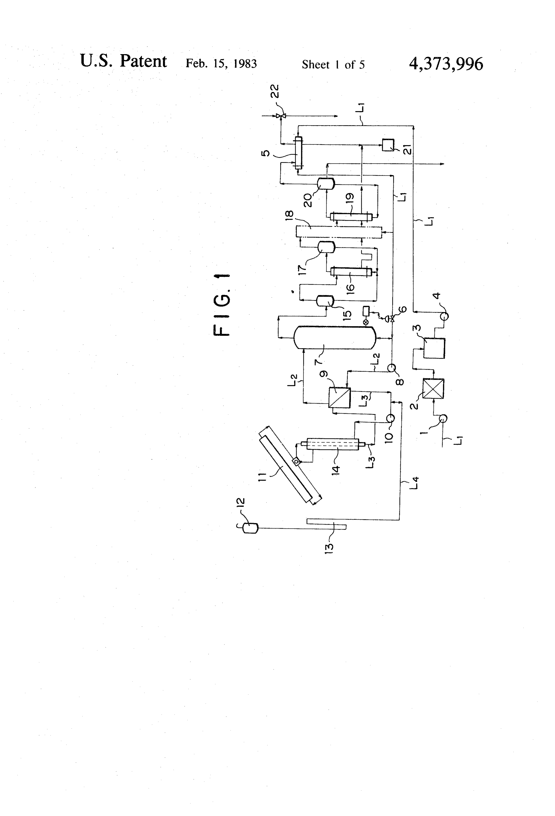
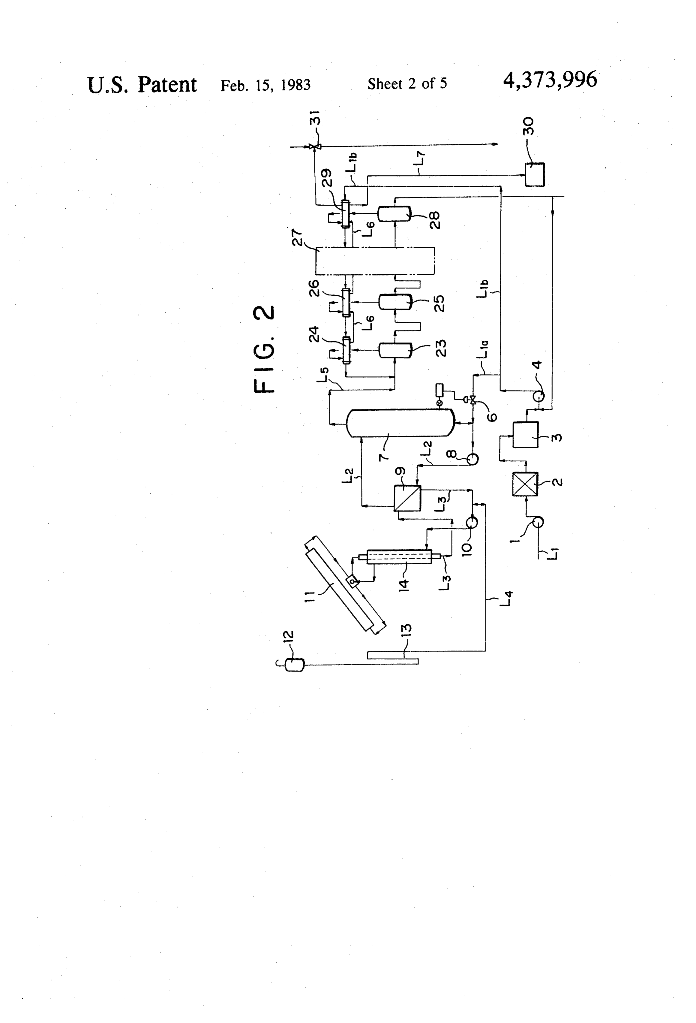
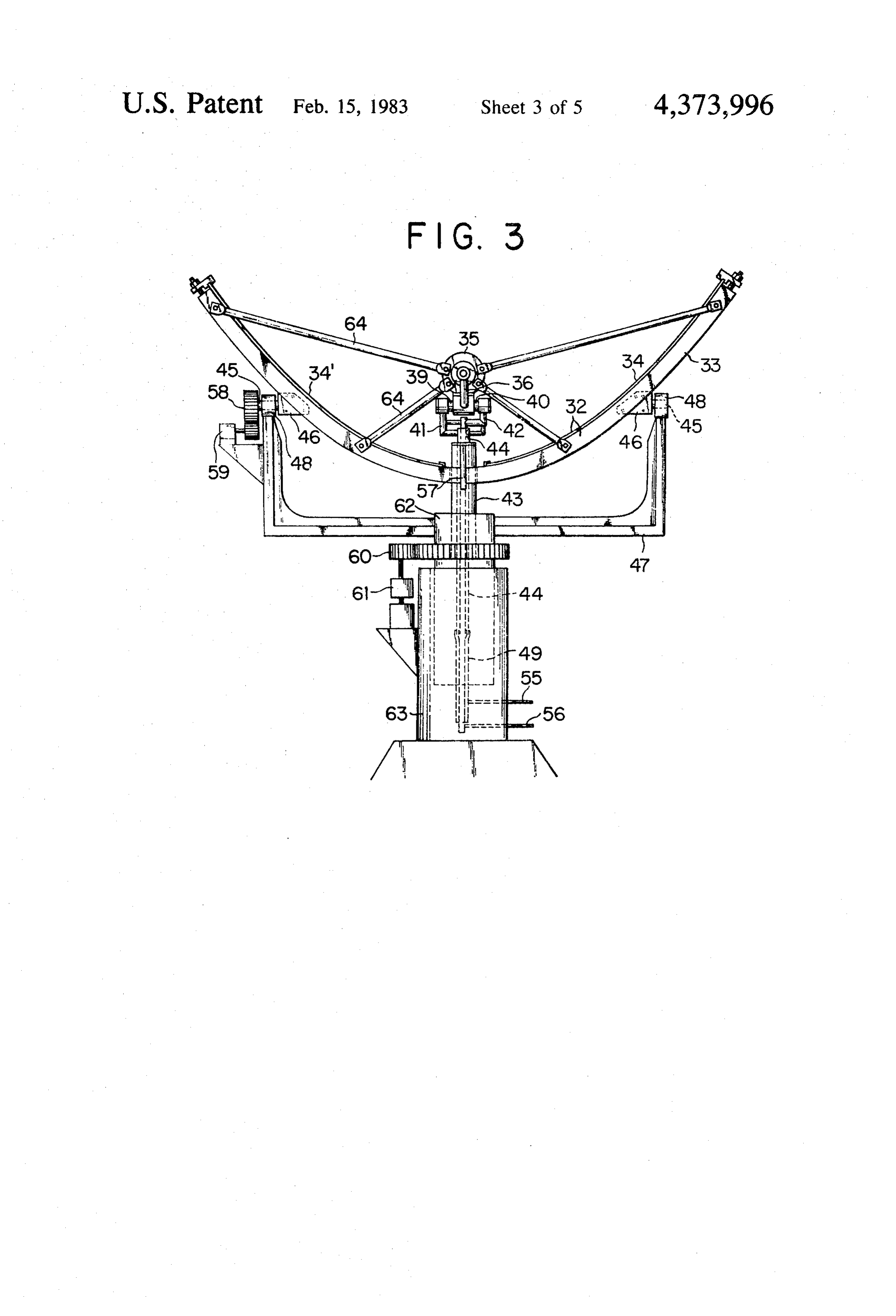
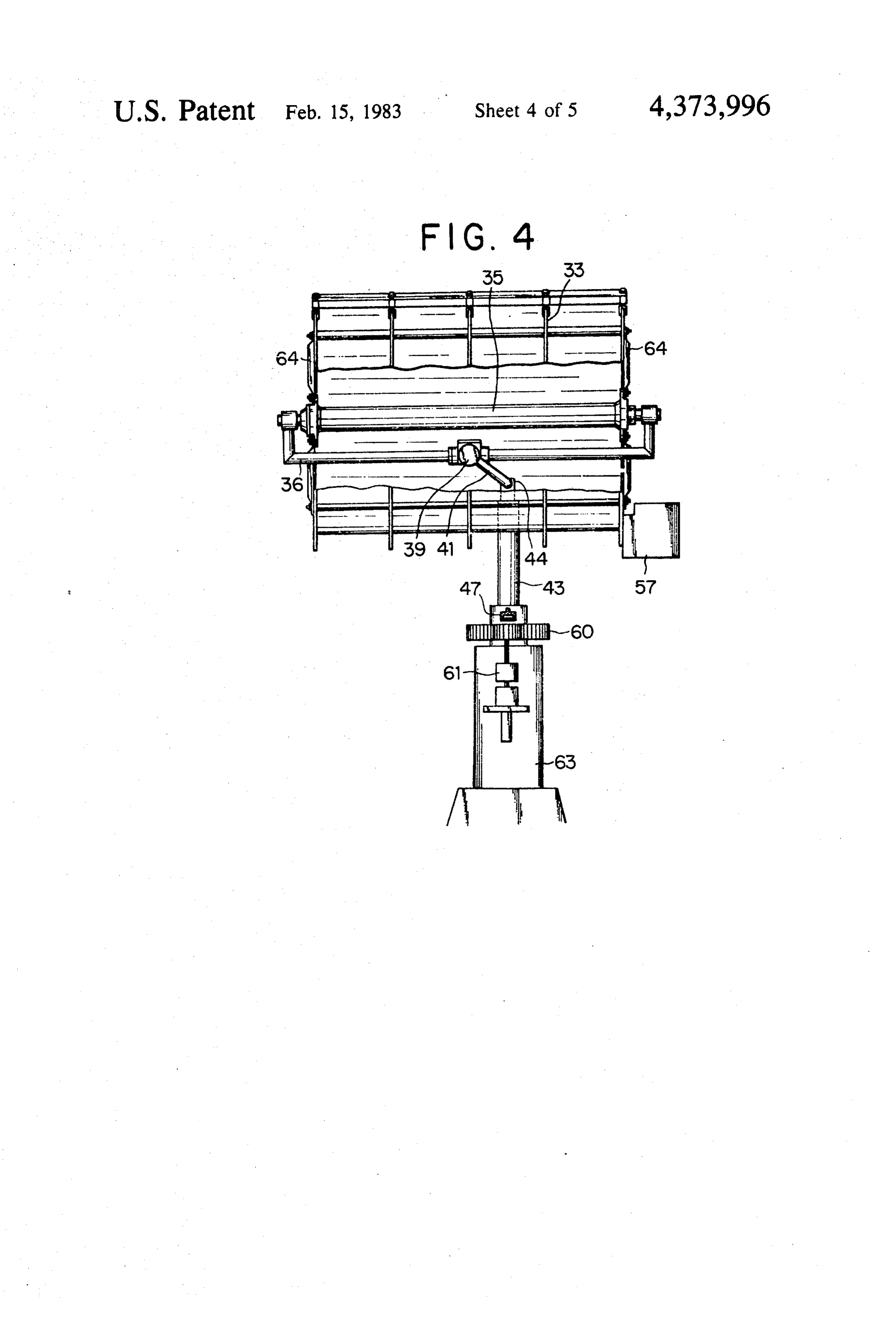
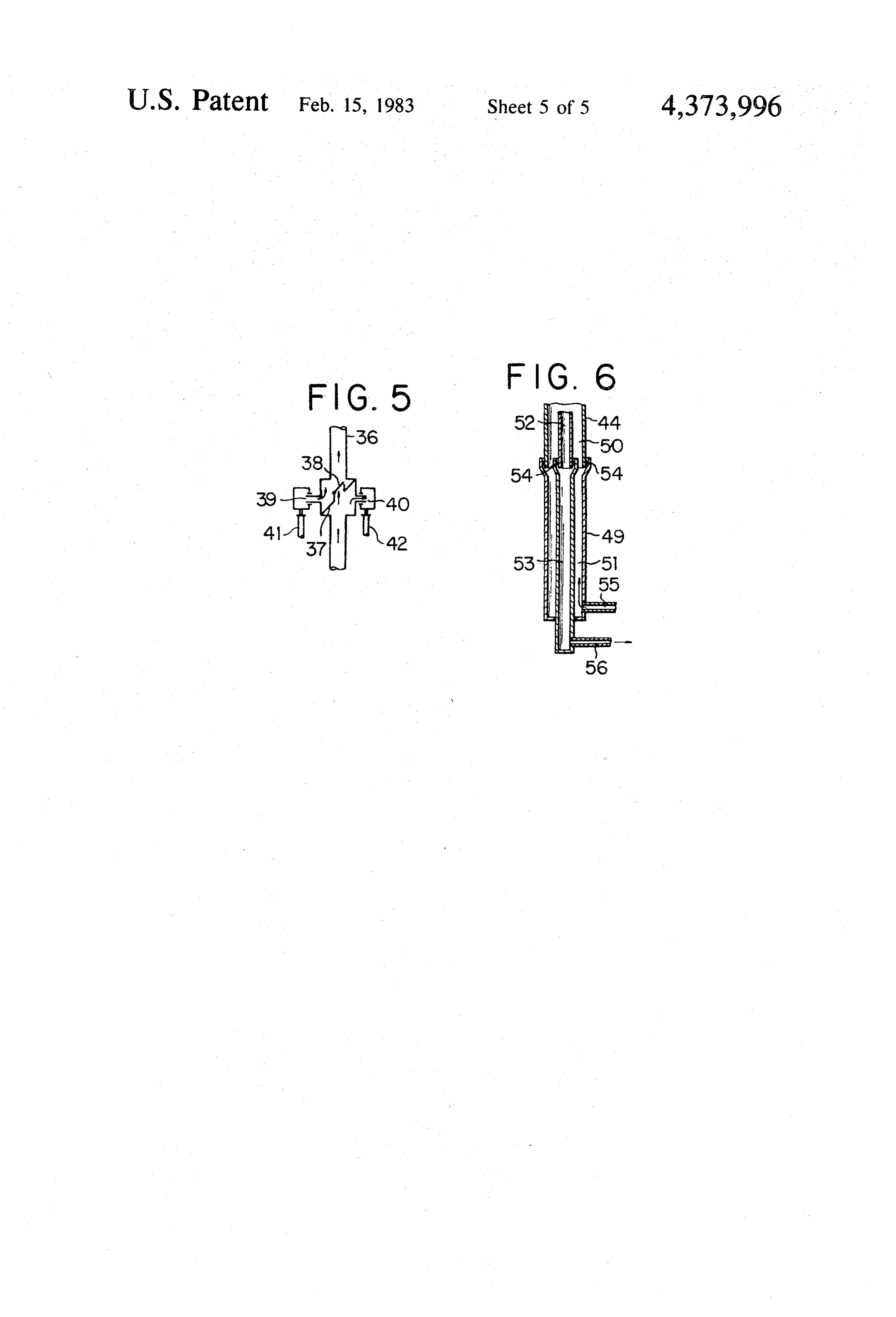
FIG. 2 is a diagram of another embodiment of the
Page 2drawing sheetscan →
Page 3drawing sheetscan →
Page 4drawing sheetscan →
Page 5drawing sheetscan →
Page 6drawing sheetscan →
Page 7scan →
FIG. 2 is a diagram of another embodiment of the
APPARATUS FOR PRODUCING FRESH WATER apparatus for producing fresh water from sea water FROM SEA WATER constructed in accordance with the present invention; FIG. 3 is a schematic side elevational view of a solar
BACKGROUND OF THE INVENTION 5 heat utilization apparatus with which the apparatus of This invention relates to an apparatus for continu theFIG. present invention is used; 4 is a front elevational view of said solar heat ously producing fresh water from sea water at less ex utilization apparatus as shown in FIG. 3; pense day and night through the utilization of solar FIG. 5 is a fragmentary schematic elevational view of heat. 10 the mechanism for prevention of cold liquid discharge There have been proposed and practically employed a variety of apparatus for producing fresh water from of 3 the solar heat utilization apparatus as shown in FIGS.
and 4; and sea water. The prior art apparatus are generally classi FIG. 6 is a fragmentary schematic view showing the fied into the multi-stage flash type, multi-effect evapora relationship between the dual rotary shaft and the dual tor type and electrodialysis type. Any one of the prior 15 stationary shaft art apparatus is required to consume expensive energy. shown in FIGS.of3said solar heat utilization apparatus as and 4.
Until the present invention, any high efficiency appara tus for producing fresh water from sea water through PREFERRED EMBODIMENTS OF THE the utilization of less expensive energy source such as INVENTION solar heat has not been developed. And since the sun 20 The present invention will be now described refer emits heat energy only during the period of time from ring to the accompanying drawings and more particu sunrise to sunset and the energy amount obtainable from larly, to FIG. 1 thereof in which the first or preferred the sun tends to be reduced when the sun is covered embodiment of the apparatus for producing fresh water with clouds, it is very difficult to continuously produce from sea water constructed in accordance with the fresh water from sea water through the utilization of 25 principle of the present invention is shown. solar heat by the prior art apparatus. The embodiment of FIG. 1 is operated on the multi In order to solve the above-mentioned problem, I effect evaporator principle in which heat medium ob have exerted myself to develop an apparatus for pro tained from a solar heat collector is caused to effect ducing fresh water from sea water and have found that heat-exchange with sea water to be evaporated and the if such an apparatus is provided with an accumulator 30 sensible heat of the sea water under a relatively low which utilizes the sensible heat of sea water to evapo pressure and at a temperature below the boiling point rate the water at a temperature above 100° C. under thereof and corresponding to accumulator pressure is pressure, fresh water can be produced from sea water utilized.
day and night. A sea water feed line L1 is in communication at one SUMMARY OF THE INVENTION 35 end with a sea water source such as the sea and at a point adjacent to the other end with the bottom of an
According to the present invention, there is provided accumulator 7. Provided in the sea water feed line L1 an apparatus for producing fresh water from sea water are a fresh sea water pump 1, a sea water filter 2, a which comprises a vertical accumulator adapted to filtrate reservoir 3, a pump 4, a condenser 5 associated utilize the sensible heat of sea water to evaporate the with a final stage evaporator and a pressure regulator 6 water at a temperature above 100 C. under pressure, a as seen from the upstream. Thus, sea water from the sea heat-exchanger provided in a line connecting between water source is pumped by the pump 1 to the filter 2 the upper and lower portions of the accumulator for where the sea water is filtered and the filtered sea water causing an elevated temperature liquid obtained from a then flows into the filtrate or filtered sea water reservoir solar heat collector to effect heat-exchange with sea 45 3 from which the sea water is fed under pressure by the water to be evaporated and a fresh sea water feed line pump 4 to the condenser 5 associated with the final connected to the bottom of said accumulator to adjust stage evaporator and in the condenser 5, the sea water the pressure within the accumulator so that the upper is caused to effect heat-exchange with vapor present in portion of the accumulator holds higher temperature the condenser. After the heat-exchange, the sea water sea water and the lower portion of the accumulator 50 flows through the pressure regulation valve 6 which holds lower temperature sea water, said accumulator adjusts the pressure of the sea water to a predetermined accumulating heat so that when heat is accumulated the pressure and then flows into the accumulator 7 at the amount of said higher temperature sea water increases bottom of the accumulator 7 so as to maintain a constant and when heat is radiated, the amount of higher temper pressure within the accumulator.
ature sea water decreases whereby sea water evaporates 55 The sea water feed line L1 leads to a pump 8 from at all times. which a recycle line L2 leads to the upper portion of the The above and other objects and attendant advan accumulator 7 and provided in the recycle line L2 be tages of the present invention will be more readily ap tween the pump 8 and the upper portion of the accumu parent to those skilled in the art from a reading of the lator 7 is a heat-exchanger 9. Connected to the heat following detailed description in conjunction with the 60 exchanger 9 is a second recycle line L3 which leads to a accompanying drawings which show preferred embodi solar heat collector 11. Provided in the second recycle ments of the invention for illustration purpose only, but line L3 are a pump 10 and a heat-exchanger 14 between not for limiting the scope of the same in any way, the collector 11 and pump 10.
When the sun shines, the pump 8 is operated to pump
BRIEF DESCRIPTION OF THE DRAWINGS 65 the sea water introduced into the feed line L1 and the FIG. 1 is a diagram of one preferred embodiment of sea water present in the lower portion of the accumula the apparatus for producing fresh water from sea water tor 7 to the heat-exchanger 9 where the two sea waters constructed in accordance with the present invention; are caused to effect heat-exchange with heat medium at 8 an elevated temperature and the resulting water then the sea water by piecemeal in the succeeding stage flows into the upper portion of the accumulator 7. evaporation chambers at stepwise reduced pressure When the sun does not shine, with the pump 8 main stage after stage and the vapor generated in the preced tained in its inoperative position, the sea water supplied ing stage evaporation chamber flows into the heater from the external sea water source into the feed line L1 associated with the next following stage evaporator to is allowed to flow through the line L1 into the lower effect heat-exchange with the sea water in the heater to portion of the accumulator 7 while heat medium is be condensed. The vapor generated in the last stage pumped by the pump 10 into the solar heat collector 11 evaporation chamber 20 flows into the condenser 5 in where the temperature of the heat medium is raised and which the vapor effects heat-exchange with the sea the elevated temperature heat medium then flows into 10 water freshly supplied to the apparatus of the present the heat-exchanger 9 to effect heat-exchange with the invention to be condensed therein. Reference numeral sea water in the heat-exchanger. After the heat 18 schematically denotes the heaters and evaporation exchange, the heat medium is recycled to the solar heat chambers associated with the intermediate stage evapo collector 11. Since the heat medium is raised its temper rators. Reference numeral 19 denotes a heater associ ature in the solar heat collector 11, an expansion tank 12 15 ated with the last stage evaporator. The sea water con is preferably connected to a heat medium recycle line densed in each stage is collected into a fresh water L4 through a U-seal 3. The heat medium recycle line reservoir 21. The multi-effect evaporator system is L4 is preferably provided with a heat-exchanger 14 so maintained under vacuum condition by a vacuum gen that the heat medium at an elevated temperature from erator 22.
the solar heat collector i0 is caused to effect heat 20 The reason for which sea water is caused to effect exchange with the heat medium to be recycled from the heat-exchange with heat medium instead of being di heat-exchanger 9 to the solar heat collector 11. rectly fed to the solar heat collector is that if the sea Assuming that solar energy or heat is available from water is heated to a high temperature on the order of the very time of sunrise, the pump 10 is operated to 200° C., it is required to increase the pressure in the pump the heat medium to the solar heat collector 11 to 25 system to a value above 15.8 atmospheric pressure and be raised its temperature. However, in such a case, the thus, there are problems with respect to the resistance amount of heat medium to be pumped to the solar heat of the slidably seal and heat collector tube of the solar collector 11 is adjusted by a valve (not shown) in con heat tube against pressure and the solution of such prob formity with the amount of available solar heat so that lems increases the production cost of the solar heat the heat medium maintained at a constant temperature 30 collector.
and the supply amount of sea water to be caused to Therefore, the solar heat collector 11 is supplied with effect heat-exchange with the heat medium is also ad a heat medium such as monopropylnaphthalene having justed by a valve (not shown) so that the sea water is a high boiling point under atmospheric pressure. When maintained at a constant temperature. Thus, the heat such a heat medium is employed, the heat medium can exchanger9 is of a one-pass type and the outlet tempera 35 be heated to a temperature within the range of ture of the heat-exchanger 9 is maintained at a low 200-220 C. without applying any excessive load to the temperature as much as possible. solar heat collector and sea water under pressure can be The accumulator 7 is preferably a vertically elon easily heated to a temperature above 100 C. through gated cylindrical tank and always fully filled with liquid heat-exchange with the heat medium. And among the having sea water at a substantially boiling point temper various components of the apparatus, only the accumu ature corresponding to the pressure within the accumu lator 7 and the lines associated with the accumulator are lator 7 contained in the upper portion thereof. required to have a construction having resistance The device adapted to evaporate the sea water at the against pressure and thus, the apparatus can be econom substantially boiling point temperature present within ically manufactured.
the upper portion of the accumulator 7 and produce 45 The accumulator 7 is always filled with liquid and the fresh water from the sea water may be a conventional upper portion of the accumulator holds sea water at a multi-effect evaporator system. The mechanism for higher temperature approximate to its boiling point evaporating sea water by the multi-effect evaporator corresponding to the pressure within the accumulator system will be now described. When the sea water at while the lower portion of the accumulator holds sea the substantially boiling point temperature is supplied 50 water at a lower temperature. However, when a certain from the upper portion of the accumulator 7 to a first amount of the higher temperature sea water flows out stage evaporation chamber 15, the temperature of the of the accumulator upper portion into the first stage sea water is reduced to its boiling point corresponding evaporation chamber 15, lower temperature sea water to the pressure within the accumulator 7 in the evapora in the same amount as that of the higher temperature sea tion chamber 15 because the first evaporation chamber 55 water which has flowed out of the upper portion is 15 is maintained at a pressure below the pressure of the supplied into the accumulator lower portion to define accumulator 7 and the sea water is evaporated in an an interface between the higher and lower temperature amount corresponding to the difference between the sea waters. Although a sharp temperature gradation is enthalpy of the fresh sea water and that of the sea water present adjacent to the interface, the sea water in the at the boiling point temperature within the first stage 60 upper portion and that in the lower half are prevented evaporation chamber 5. The generated vapor flows from mingling with each other. When solar energy is into the outer cylindrical portion of a double-walled available from the very time of sunrise, the interface heater 16 associated with a second stage evaporator to which has moved to a substantially high position within be raised its temperature and the vapor at the elevated the accumulator 7 descends gradually whereby the temperature then flows into a second stage evaporation 65 amount of the higher temperature sea water increases chamber 7 to heat the sea water within the evaporation correspondingly. And when the heat medium holding chamber 7. The same procedure is repeated in the capacity of the solar heat collector 11 is designed to be succeeding stages including the last stage to evaporate equal to the quantity of heat required for evaporation of 9 sea water so that the interface comes down to a substan condenser 29. Thereafter, the sea water under pressure tially lowermost position within the accumulator 7, the in succession passes through the condensers associated capacity of the accumulator 7 is determined depending with intermediate stage flash tanks, the second stage upon the amount of heat necessary for evaporation of condenser 26 associated with a second stage flash tank sea water at night with the sensible heat of sea water to 5 25 and the first stage condenser 24 associated with the be evaporated. first stage flush tank 23. Each time the sea water under Assuming that the amount of sea water to be recycled pressure passes through the successive stage condens is 1 when the sun shines, the amount of higher tempera ers, the sea water effects heat-exchange with the vapor ture sea water which flows out of the accumulator 7 is in the condensers to increase its temperature step by 0.5 and that of lower temperature sea water is also 1.5 O step. After having passed through the first stage con whereby the amount of sea water equivalent to 0.5 denser 24, the now high temperature sea water flows becomes to have a higher temperature and the volume into the recycle line L5 where the sea water mingles of the higher temperature zone of the accumulator in with the high temperature sea water from the upper creases to move the interface between the higher and portion of the accumulator 7 and the resulting sea water lower temperature sea waters downwardly. 15 then flows into the first stage flash tank 23. Reference The accumulator 7 has a diameter substantially numeral 27 schematically denotes the intermediate greater than that of the recycle line L2 and there is stage flash tanks and associated condensers. neither sea water turbulent flow nor sea water counter The vapor generated in the first stage flash tank 23 is flow within the accumulator 7 and only heat transfer supplied to the first stage condenser 24 in which the occurs through the heat conductivity of sea water (from vapor effects heat-exchange with the sea water. Simi the higher temperature sea water to the lower tempera larly, the vapor generated in each of the successive ture sea water) to define the interface between the stage flash tanks is supplied to the condenser associated higher and lower temperature sea waters. In order to with the respective tank to effect heat-exchange with design the accumulator 7 in such a way, it is necessary the sea water in the condenser and the condensed sea to supply the sea water from the source through the 25 water obtained in each of the condensers in succession feed line L into the accumulator 7 at the bottom of the passes through the respectively succeeding condenser accumulator 7. by way of a line L6 connecting between the adjacent The condensation ratio of sea water to be evaporated condensers to the last stage condenser 29 from which or the inlet sea water amount to the outlet sea water the condensed sea water passes through a line 7 to a amount ratio is determined depending upon the temper 30 condensed water reservoir 30 where the condensed ature in the upper portion of the accumulator 7 and the water is accumulated and the sea water from the last number of the stages in the multi-effect evaporation stage flash tank 28 discharges out of the system. system, but in order to increase heat effect, the conden In the embodiment of FIG. 2, the condensation ratio sation ratio inevitably exceeds the critical range of of sea water is determined depending upon the tempera 1.35-1.37 within which no scale is formed and in order 35 ture of sea water to be supplied to the first stage, but in not to exceed the critical condensation ratio, the con order that the sea water processing operation is carried densation ratio is adjusted by introducing a partially out in one pass mode so as to maintain the condensation pre-heated sea water into a stage adjacent to the final ratio within the range of 1.35-1.37 in which no problem stage (any one of the intermediate stages 18 in the em such as scale occurs, the temperature within the first bodiment of FIG. 1). 40 stage flash tank 23 rises to an excessively high value The embodiment of FIG. 2 is designed to operate the which applies a prohibitive load to the apparatus for accumulator 7 at a relatively high temperature (about producing fresh water from sea water by the utilization 200 C.) by a multi-stage flash system. Since the mecha of solar heat. Thus, according to the present invention, nism incorporating the accumulator 7 therein is similar a portion of the condensed sea water discharged out of to that as described hereinabove, only the mechanism 45 the system is introduced into the fresh sea water feed for evaporating sea water will be now described refer line L1 to mingle with the fresh sea water supplied from ring to FIG. 2. the sea water source to the feed line L1 and the resulting The sea water feed line L1 is branched downstream of sea water is recycled within the system to adjust the the pump 4 into a first branch line L1 and a second condensation ratio of the sea water. Such arrangement branch line L1b. The first branch line L1 connects to 50 is economically advantageous in the fact that a small the bottom of the accumulator 7 and has a pressure capacity heat-exchanger (not shown) can be used for regulating valve 6 interposed between the pump 4 and recovering the sensible heat of the condensed sea water accumulator 7. The first branch line L1 is also con to be discharged out of the system or such a heat nected at the other end to a recycle line L.2 which is in exchanger can be eliminated. In FIG. 2, reference nu turn connected to the upper portion of the accumulator 55 meral 31 denotes a vacuum generator. 7. The second branch line L1b extends through a last The solar heat collector with which the apparatus of stage condenser 29, a second stage condenser 26 and a the present invention is used is not exclusively limited to second stage condenser 24 and connects to a line L5 a specific device provided that the collector can heat which feeds sea water from the upper portion of the heat medium to a high temperature. For example, the accumulator 7 to a second flash tank 23. Thus, a portion solar heat collector employed in the solar heat utiliza of sea water under pressure pumped by the pump 4 is tion apparatus as disclosed in my co-pending U.S. Ser. passed through the valve 6 and then sub-divided into No. 119,882 now U.S. Pat. No. 4,317,444 and the sun two flows one of which flows into the accumulator 7 following-up device for solar heat utilization apparatus and the other of which flows into the recycle line L2. as disclosed in my co-pending U.S. Ser. No. 219,120, are The rest of the sea water under pressure passes through 65 most suitably employed. The former is an apparatus the last stage condenser 29 associated with a last stage adapted to focus sunlight so as to utilize the solar heat flash tank 28 and effects heat-exchange with vapor gen and the latter is adapted to cause the sunlight reflector erated in the flash tank 28 and is then supplied to the to follow up the sun.
Page 10scan →
The solar heat utilization apparatus of the above-men A rudder 57 is attached to the framework of the sun tioned U.S. patent application will be now described light reflector and a gear 58 is mounted at the outer end referring to FIGS. 3 through 6 in which the solar heat of one of the horizontal rotary shafts which is opera collector is schematically shown. The sunlight reflector tively connected to a drive means such as a motor for 32 generally comprises a grid structure framework 32 driving the particular stub shaft. Reference numeral 60 curved so as to define a parabolic trough and metal denotes a gear for the vertical rotary shaft, reference plates 34, 34' secured to the framework so as to form the numeral 61 denotes a drive means for the vertical rotary mirror face of the reflector. A heat collecting means 35 shaft, reference numeral 62 denotes a pipe for the verti is provided at the focus of the parabolic trough of the cal rotary shaft, reference numeral 63 denotes a pillow reflector 32. Connected to the heat collecting means 35 10 block for the vertical rotary shaft and reference nu is a liquid circulating pipe 36 and liquid to be heated meral 64 denotes a support rod. While only one embodiment of the invention has been flows from the pipe 36 into the heat collecting means 35 shown in which the liquid is heated with the heat from the same is and described, it will be understood that the for illustration purpose only and not to be taken sunlight by absorbing the sunlight therein and the as a definition of the invention, reference being had for heated liquid then flows back into the circulating pipe 15 36. The circulating pipe 36 is provided in an intermedi thisWhatpurpose to the appended claims. is claimed is:
ate section between the opposite ends thereof with a 1. An apparatus for producing fresh water from sea mechanism for prevention of cold liquid discharge (see water comprising:
FIG. 5) and the mechanism includes a partition plate 37 a solar heat collector having an inlet and an outlet, in the center portion thereof and horizontal inlet and closed loop conduit means interconnecting said inlet outlet pipes 39, 40 are connected to the opposite sides of and outlet of said collector for passing there the circulating pipe 36. The inlet tube has a liquid sup through a high temperature liquid, ply tube 41 connected thereto and the outlet pipe 40 has a first pump in said closed loop conduit means, a discharge tube 42 connected thereto. The liquid sup a heat exchanger having first and second inlets and ply tube 41 and discharge tube 42 are connected to a first and second outlets, said first inlet and first common rotary double tube 44 which is in turn disposed 25 outlet being connected to said closed loop conduit coaxially within a hollow vertical rotary shaft 43 for means for passing said high temperature liquid rotation together with the latter. through one side of said exchanger, A pair of opposite shaft support members 46 are pro a vertical accumulator having a bottom, a lower por vided in diametrically opposite positions of the frame 30 tion, an upper portion, and a top, work 33 of the sunlight reflector to support the inner a first sea water feed line connected to said bottom of ends of a pair of horizontal stub shafts 45 and the other said accumulator, or outer ends of the stub shafts are journalled in bear a pressure regulator in said first sea water feed line ings 48 which are in turn suitably supported by the free upstream of said bottom for regulating the pressure ends of the opposite legs of a frame member 47 secured 35 in said accumulator to a predetermined pressure to the vertical rotary shaft 28. The horizontal rotary above atmospheric pressure, stub shafts 45 are disposed coaxial or substantially coax a second sea water line connected from said first sea ial with the liquid inlet and outlet tubes 39, 40. water feed line adjacent said bottom to said second The rotary double tube 44 is connected at the lower inlet of said exchanger, end to a double stationary shaft 39 which is also in the 40 a second pump in said second sea water line, form of a double tube. The outer tube 50 of the double means for shutting down said second pump when the tube 44 is in communication with the outer tube 51 of sun is not shining, the stationary shaft 49 to form a supply passage for a third sea water line from said second outlet of said liquid to be heated. The inner tube 52 of the rotary exchanger to said upper portion of said accumula double tube 44 is in communication with the inner tube tor, 53 of the stationary shaft 49 to form a discharge passage 45 an evaporator, and for the liquid after the liquid has been heated. In the a fourth sea water line from said top of said accumula illustrated solar heat utilization apparatus, the sealing tor to said evaporator, between the outer and inner tubes of the rotary tube 44 said upper portion of said accumulator receiving and stationary shaft 49, respectively, is not required to higher temperature sea water from said exchanger closely tight, but may be just sufficient to prevent leak 50 when said second pump is operating, said lower age of the liquid to the exterior of the system. In the portion holding lower temperature sea water, example as shown in the drawings, O-rings 54 are em whereby when the sun is shining, a proportion of ployed to seal the rotary tube 44 and stationary shaft 49. higher temperature sea water in said accumulator The outer tube of the stationary shaft 49 is connected increases displacing the lower temperature sea water therein out of said bottom and when the sun at the lower end to a supply tube 55 and the inner tube 55 is not shining, higher temperature sea water is fed of the stationary shaft is connected at the lower end to from the upper portion of the accumulator to said a discharge tube 56 for heated liquid, respectively. The evaporator by being pushed out by said lower tem liquid from the supply tube 55 associated with the sta perature sea water coming in said bottom so that tionary shaft 34 passes through the supply passage de said evaporator is constantly supplied with higher fined by the outer tubes of the stationary shaft 49 and 60 temperature sea water regardless of whether the rotary tube 44 to and through the supply tube 41 of the sun is shining or not.
circulating pipe 36 connected to the outer tube 50 of the 2. The apparatus for producing fresh water from sea double tube 44. The heated liquid discharged from the water as set forth in claim 1, in which said evaporator is pipe 36 flows through the discharge tube 42 into the a multi-effect evaporator.
discharge passage defined by the inner tubes of the 65 3. The apparatus for producing fresh water from sea rotary tube 44 and stationary shaft 49 and then into the water as set forth in claim 1, in which said evaporator is discharge tube 56 of the stationary shaft 49 to be dis a multi-stage flash evaporator.
charged out of the system. s s:
Provenance
- Collection
- Patents citing this work
- Pages
- 10
- Method
- pdftotext (the PDF's own text layer) + pdftoppm 300dpi page scans
- Patent office record
- patents.google.com →
- Source
- Google Patents citing-documents table
- Assignee
- Saburo Maruko
- Published
- 1983-02-15
- Transcribed from
- patentimages.storage.googleapis.com →