

patent · US4382434A
Prismatic tracking insolation collector
10 May 1983
Text
Page 1scan →
United States Patent (19)
Meckler
(54) prismatic tracking insolation
Collector
76) Inventor: Milton Meckler, 16348 Tupper St.,
Sepulveda, Calif. 91348
Related U.S. Application Data
51) Int. C. ................................................. F24J 3/02 52 U.S. C. .................................... 126/425;y 126/438:
1,683,266 9/1928 Shipman .... ... 126/438 2,803,591 8/1957 Coanda ..... ... 126/438 3,884,217 5/1975 Wartes ................................ 26/438
4,068,474 1/1978 Dimitroff ............................ 126/439 4,139,286 2/1979 Hein et al. .............................. 353/3 4,148,300 4/1979 Kaufman ....... ... 126/438 4,168,696 9/1979 Kelly ......... ... 126/440 4,204,881 5/1980 McGrew ....... ... 126/438 4,205,661 6/1980 Chapman ... ... 126/425 4,249,516 2/1981 Stark ............. ... 126/439 4,257,401 3/1981 Daniels ...... ... 126/440 4,321,909 3/1982 Trihgy .............. ... 126/425 4,337,759 7/1982 P ich et al. ................... 26/438 rimary Examiner-Daniel J. O'Connor
Attorney, Agent, or Firm-William H. Maxwell
Abstract
A trackingB insolation collector characterized by elon gated prisms of acute apex angle maintained with an objective face disposed normal to the sun rays and through which dispersed light is projected from a trans mission face and onto a coordinated mirror for geomet ric focus onto a target, the heat rays of the spectrum being concentrated onto the target by lens means on the plane of said projection, an astro timer revolving the prisms and mirrors throughout reversed morning and afternoon verse planetracking modes in alignment with the tra of the sun.
13 Claims, 9 Drawing Figures
Drawings
Page 2drawing sheetscan →
Page 3drawing sheetscan →
Page 4drawing sheetscan →
Page 5scan →
trum selected for heating and to project it exclusively.
PRISMATIC TRACKING NSOLATON As stated above, the dispersion is by means of a pris COLLECTOR matic solid which refracts bands of light along angu larly divergent "focal lines or planes'. Accordingly, a
This is a continuation in part application of applica- 5 linear lens having a focal line or plane is aligned with tion Ser. No. 30,328, filed Apr. 16, 1979, now aban the median focal plane of the selected spectrum portion doned, and is copending with application Ser. No. emitting from the prism to project the same to the target 271,837 filed on even date herewith. collector or converter also of linear form at the point of
Background
focus. In practice, a linear Fresnel lens is used for this 10 projection.
The collection of solar energy for heating and the Tracking of the sum in its traverse between horizons generation of power involves the radiation of sunlight is either by bodily movement of the apparatus herein onto conduits and power generating cells; conduits disclosed or preferably by turning of the prism dis transporting a heat transfer media and/or energy con closed in a plane substantially normal to the sun in its verters that directly produce electrical power. Solar 15 movement across the sky. In practice, a clock drive quantity or concentration becomes a primary consider more specifically referred to as an "astro timer' is em ation for the impingement of light rays onto said collec ployed to revolve the prism in order to maintain sub tor tubes or converters, and heretofore the white light stantial alignment of the aforesaid "focal plane' of the of the sun rays has been concentrated for so-called high prism and lens projection respectively. Nominal opera temperature heat collection or conversion. However, it 20 tional time periods are accommodated by revolvement is known that the longer "red" (infrared) rays of light of the prism alone, while extended operational time are those which have the greater heating effect, while periods are accommodated by combining therewith a the shorter "violet' or "ultraviolet' rays have the lesser reflective mirror that also moves with the astro timer or heating effect and are required, for example in clock drive to track the selected spectrum onto the photovotaic power generation. Furthermore, when 25 target. A feature is the use of an array of prismatic considering photovoltaic power generation, only high projection units and each with its prism and mirror energy photons (some 45% of the solar radiation) will articulated to concentrate the selected spectrum onto be effective, ie the ultraviolet and some of the visible the target collector or converter for high heat and/or spectrum, but not the infrared. Also, those invisible power operation. In practice therefore, each mirror has infrared rays just beyond the "red' of the visible spec 30 its angular adjustment to the target, and the distance to trum have known penetrating heating effect. Therefore, the target from each prism unit is accommodated by the it is a general object of this invention to advantageously focal length of its projection lens or a collection lens. employ either or both of those rays, namely infrared The optics of the collector prism is critical, with the and ultraviolet at opposite ends of the spectrum, and of apex B uppermost and the quadralateral faces AB and the sun which are known to have said effects, in prefer-35 CB active to refractively pass sunlight so as to disperse ence to those rays that do not; and to this end dispersion the same into the utilitarian spectrum, especially the is employed to break sunlight into its parts which are heat portion thereof. In accordance with this invention then selectively focused upon a target collector or con the lowermost quadralateral face AC is inactive and in verter as circumstances require. practice is frosted so as to be non-reflective. Accord The prism is a solid transparent body that refracts 40 ingly, a feature is the reduction of internal reflection light, and strictly speaking is a solid figure with ends of within said prism by maintaining substantial normality equal size and shape in parallel relation and whose sides of the face AB to the solar source rays and by careful extending therebetween are parallelograms. The most selection of the acute angle at the apex B. Therefore, the common prism is a triangular solid of glass or the like, critical angle of the prism is at the apex B, and the opti for refracting and dispersing light into and beyond the 45. mum of which has been found to be approximately 36 visible spectrum ranging from infrared heat rays to the based on an air to glass interface and which varies as a power generating ultraviolet rays. Dispersion in the function of the respective indicies of refraction, for the prism is by means of refraction or the bending of light substantial elimination of internal reflection and for the rays as they pass obliquely from one medium (air) to the purpose of conducting the tracking function through a other (glass or plastic) or different density in which its 50 wide range, and especially in combination with a mirror speed changes; a phenomenon thereby breaking the M that contra rotates therewith at a ratio of 1 to 2. That light into its constituent parts represented by the bands is, the mirror rotation is 1 to 2 of prism rotation. The of the spectrum. It is an object therefore to advanta relatively small apex angle of the prism operates in geously employ said prismatic phenomenon and con conjunction with the tracking mirror without the for centrate therefrom a range of heat rays which is most 55 mer blocking light, especially in the heat spectrum por practical as may be required for application to the target tion, from the latter. S. collector or converter. The heat collector and/or power converter can vary The selection of heat rays involves an alignment with in form and in construction, however it is disposed that portion of the spectrum both visible and invisible, linearly along the focus of the at least one prismatic-lens and the projection of that portion upon the collector or collector above referred to. A feature of this invention converter. The projection of selected heat rays can be is the conservation of concentrated heat in the collector direct or concentrated and at a 1 to 1 ratio or at a or converter at the point of focus, and which is structur concentration ratio for developing commensurately ally compact while the collecting prism and tracking high temperature or energy at the target. That is, direct mirror are structurally expansive. In practice, the said projection is suitable for low temperature-low power 65 collector or converter is encased within a transparent operations, while concentrated projection is necessary tube, preferably vacuumized, for the substantially com for high temperature-high power operations. It is an plete absorption of energy from the heat rays impinging object therefore to concentrate that portion of the spec thereupon. A condensing reflector backs up the target 6 to return the heat rays that are or may be dispersed to 1.49 (glass 1.5) and a light transmission factor of 92%; initially pass thereby. said surface coating increasing the said light transmis DRAWINGS sion efficiency. A feature therefore is the light weight of the plastic, acrylic, prism having a slender cross section
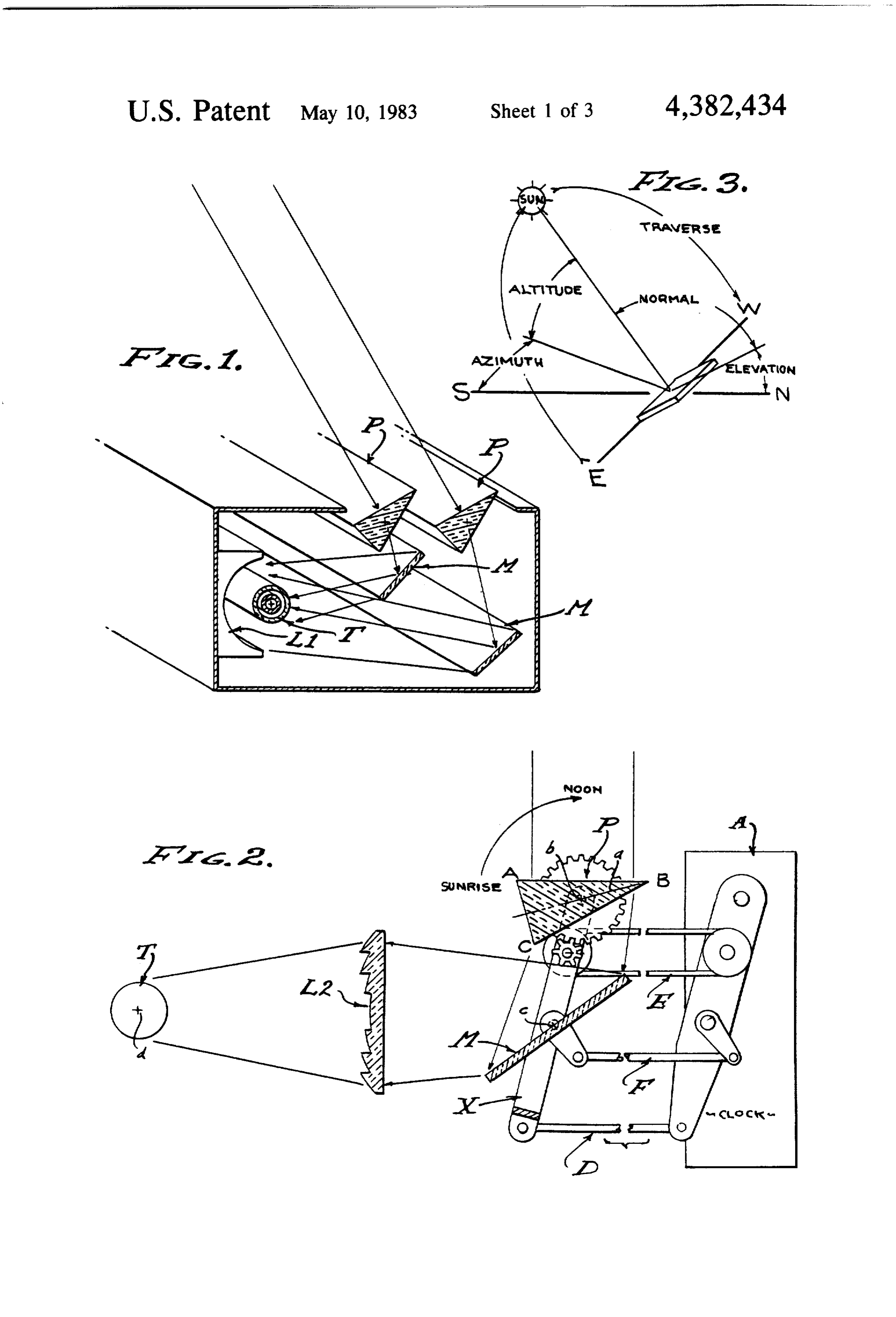
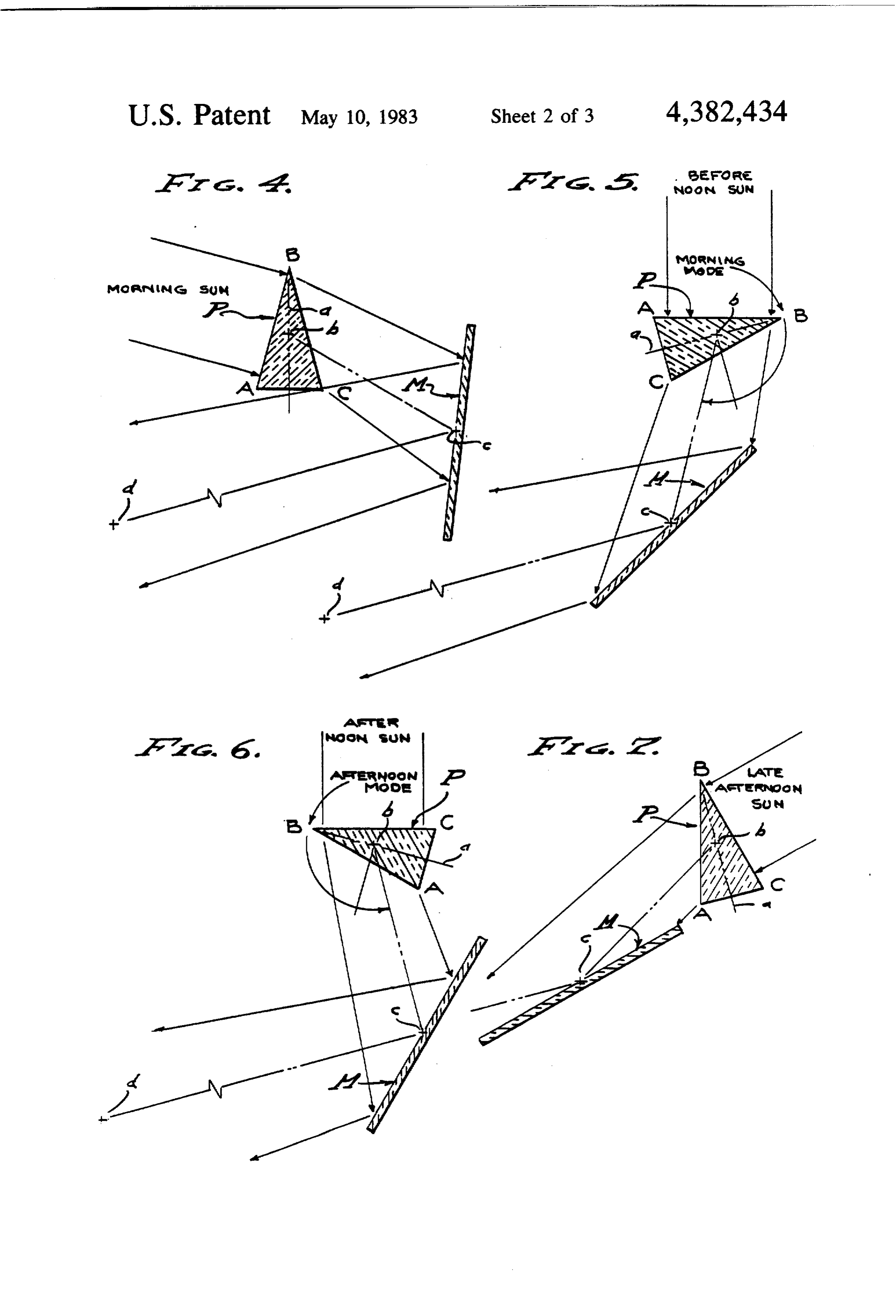
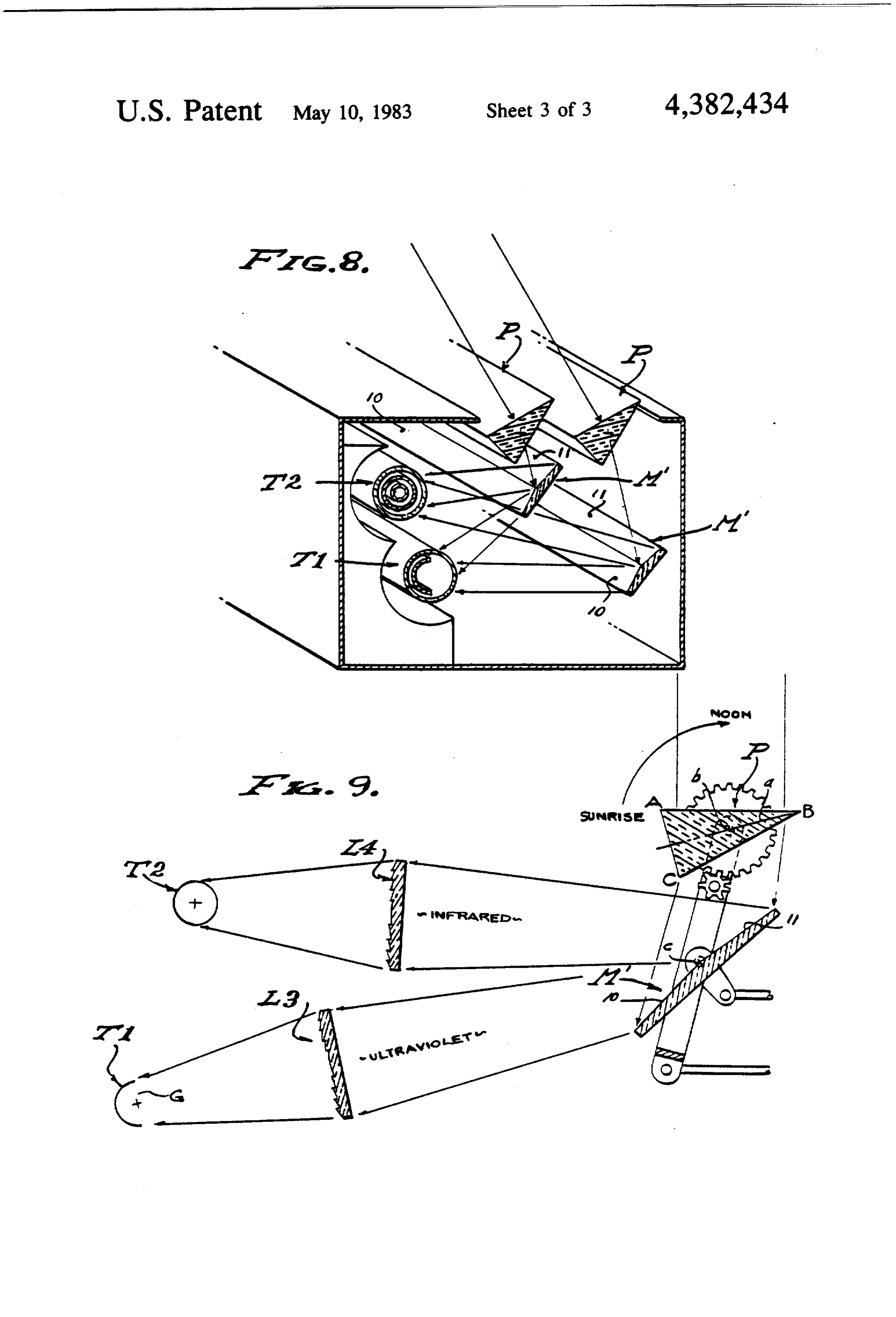
The various objects and features of this invention will 5 and with a specific gravity of 1.19; considerably lighter be fully understood from the following detailed descrip in weight than any glass and much less fragile. tion of the typical preferred forms and applications The prism Preceives parallel solar source rays which thereof, throughout which description reference is enter the normal objective face AB or CB angularly made to the accompanying drawings, in which: with respect to a bisecting median plane a within the FIG. 1 is a perspective view of the tracking insolation O prism and with no dispersion and minimized refraction. collector of the present invention, in its preferred form The parallel rays then exit through the angularly related involving an array of prisms and coordinated mirrors. 36' transmission face BC or AB with one stage of sub FIG. 2 is a detailed view showing a modified form of stantial refraction and minimized internal reflection. prismatic tracking collector involving a focusing lens. The prismatic refraction inherently produces spectral FIG. 3 is a diagramatic perspective view illustrating 15 dispersion, with the red and infrared light concentrated the altitude and traverse relationship of the sun to the toward the edge B as the light emits from said prism P. collector. The light from prism P emanates divergently from FIGS. 4 through 7 are views similar to FIG. 2 show transmission face CB or AB and plays on the target T, ing the transition between morning and afternoon oper and in accordance with the invention the heat and/or ation, and the reversal of the prism which characterizes 20 energy rays concentrated by prismatic dispersion are the morning and afternoon modes of operation. played upon the target. For example, those rays of the FIG. 8 is a perspective view similar to FIG. 1 and spectrum in the range of yellow, orange, red and unfra shows a second modified form of the present invention, red are played upon the target T for heating and/or wherein the infrared and ultraviolet light is split. energy change as the case by be. Accordingly, a dis And FIG. 9 is a view similar to FIG. 2 showing the 25 persed heat range of light rays from face CB (or AB) is split rays and each involving a focusing lens. played onto the target T, including the infrared rays
Preferred embodiment
beyond visible range.
A feature is the geometric focus of heat range rays
Referring now to the drawings, this invention in upon the target T by use of coordinate revolvement of volves primarily the use of a prism P aligned with its 30 the prism P and the mirror M (see FIGS. 4 through 7). objective face AB-CB substantially normal to the solar In practice, a first surface reflector mirror is employed, source rays, and disposed to focus heat rays onto a cast of the same acrylic plastic as the aforementioned target heat collector or energy converter. It is to be prism and surface coated and aluminized for efficient understood that the prism and collector-converter ar relfection. Accordingly, there is a switching means of rangement can be moved bodily, but that it is preferable 35 the astro timer A operating as a clock drive to actuate a to track the sun by revolvement of the prism and by lever means E that revolves the prism P on an axis b maintaining its objective face substantially normal to substantially normal to the altitude of the sun as it tra the sun rays. Accordingly, the collector assembly is verses (see FIG. 3) and so that its objective face AB or immovably disposed substantially normal to the altitude CB remains substantially normal to the sun rays emitted of the sun and with the target T fixed, while the prism in parallel relation. As shown throughout the drawings, Prevolves in timed relation to the traverse of the sun the target T is fixedly positioned as is the axis b of the under control of an astro timer A operating a means D prism P, and the mirror M is positioned by the astro which maintains the focal line at the target. In practice, timer A operating as a clock drive to actuate a lever concentration of the heat or energy portion of the spec means D about said axis b so that its alignment with trum is desired and accordingly a lens is provided to 45 prism P remains effective to focus said heat range rays focus the heat or energy rays onto the target T. And in upon the target T. As shown, a means F revolves the order to track the sun throughout a substantial portion mirror M on an axis c parallel to axis b. The means E of its traverse across the skies, a mirror M compliments and F are carried by the lever of means D to move the prism and is coupled to rotate therewith and thereby therewith, as shown. It will be seen that the prism maintain the line of focus upon the target. 50 P-mirror M combination has its projection plane b-c The prism P is an elongate solid of triangular cross and that the mirror M-target T combination has its section having parallel corners A, B and C defining projection plane c-d. The astro timer A operates as a reversely positionable faces AB and CB. The apex angle clock drive also to operate the belt or chain of the B is critical and its optimum determined to be approxi means F, as shown. Since the target T is fixedly posi mately 36 for glass air interface, while the face AC is 55 tioned, the axis b is the center of rotation of the prism inactive and frosted so as to be non-reflective. It is the P-mirror M combination when adjusting the mirror M purpose of this prism to pass a maximum amount of light angularly with respect to the prism P and target T so as and to reduce an/or practically eliminate internal re to bisect the included angle disposed between the said flection, and to these ends the objective face AB or CB projection planes b-c and c-d. Accordingly, the afore is disposed substantially normal to the solar source rays said parallel sun rays are directed toward the target T and the critical angle B minimized to 36". The transpar and divergently dispersed along plane c-d. ent highly polished faces AB and CB are surface coated The target T is a heat converter or energy generator for maximum light transmission and minimum internal as may be required. Flat plate targets may be employed, reflection. although more sophisticated vacuumized co-cylindrical Structurally, the prism P is made of glass or a plastic 65 collectors or converters are preferred. As shown for material such as "Acuvue 360" as manufactured by example, co-cylindrical tubing is disposed concentric Swedlow, Inc. of Garden Grove, California, a high with an axis d along which it conducts a heat transfer quality cast optical acrylic having a reflection index of media, the inlet of which is in the outer annulus and the 7 heat absorption and outlet of which is from a central means D,E and F actuated thereby, it is the rotative tube on the line d. The target can be an energy con positions of the prism P and mirror M that are coordi verter such as a voltaic power generating means as nated; maintaining the objective face of the prism nor shown in FIGS. 8 and 9 enclosed in a transparent tube mal to the sun rays; and maintaining the reflection of that is vacuumized so that the insolation responsive dispersion light along the plane c-d. A feature is the elements thereof are centered on the focus line d, in two modes of operation for alternately switching of said which case ultraviolet light, shorter wave lengths of the acute apex angle away from the zenith position of the spectrum, are concentrated upon the target. sun; a morning mode as shown in FIGS. 4 and 5, and an Concentration of heat range rays is provided for in afternoon mode as shown in FIGS. 6 and 7. It is to be the lens which receives the dispersed rays from the O observed that the transmission from morning to after prism P or from the mirror M. As described, the heat of noon modes is characterized by a reversal in positioning range rays are projected divergently from the prism P the prism P and mirror M, always directing light or mirror M, coextensively of the elongated prism and laterally to the fixedly positioned target T at line d. complementary mirror. Accordingly, the lens is coex Accordingly, three distinct movements are involved, tensive with the prism and/or mirror and is positioned 15 firstly the revolvement of prism Pby means E, secondly on plane b-c or c-d to embrace and collect the heat ray the shifting or reversal in position of the rotational axis spectrum, for example the yellow to infrared rays. As c of prism P and mirror M by means D, and thirdly the shown in FIG. 1, the lens L1 is a first surface reflector revolvement of said mirror M by means F. in the form of an elongated cylindrically concaved The bent angle of the dispersed rays emanating from mirror, cast of the same acrylic plastic as the aforemen 20 the transmitting face of the prism remains the same tioned prism P and mirror M, and surface coated and throughout each mode; compare FIGS. 4 with 5 and 6 aluminized for efficient reflection. Lens L1 is of linear with 7. And to these ends, the transition from morning form that concentrates the divergent spectrum by fo to afternoon mode involves means Dangularly displac cusing it onto the target line at d. Lens L1 is therefore ing the axisc from the median plane a through prism P, centered behind the target and aligned with the plane 25 in each prism mode, so that the bent angle of light is c-d to collect and concentrate insolation onto the target always directed from axis b to axis c. In practice, a T. As shown in FIG. 2, the lens is a Fresnel lens L2 of cradle X is shiftable to have two angularly displaced linear form focusing the divergent spectrum onto the positions with respect to the plane a, one as shown in target line at d. The lens L2 is therefore centered on the FIGS. 4 and 5 and at all rotative prism positions there plane c-d between the turning axis c of mirror M and 30 between, and the other as shown in FIGS. 6 and 7 and the heat concentration lined at the target T. Like the at all rotative positions therebetween. The means F prism, the lens L2 is cast of the same acrylic plastic as revolves the mirror M in response to positions of the prism P, of light weight and optically efficient. In prac lever means E, so that the reflected angle of light from tice, either or both lenses L1 and/or L2 can be simulta the mirror is always directed from c to d. In practice, neously used. 35 the means F is a lever means (as shown) that ensures The above described combinations of elements are that a line drawn normally from the mirror at axis c intended for singular use or multiple use in an array as always bisects plane b-c and plane c-d. Examination of shown in FIG. 1. It is to be understood that solar posi FIGS. 4 through 7 will bear this out, and all of which tion as related to latitude will determine effective angles occurs as the astro timer means A revolves the prism P, of elevation as shown in FIG. 3, and that the seasons 40 there being two mode relationships of prism P and the will cause variations in that angle as well as the effective cradle means X, the one where the prism face AB is the time of day for solar energy collection. Also for exam objective face, and the other one where the prism face ple, it may be that effective insolation can be realized CB is the objective face. There is a switching or rever from one hour after sunrise to one hour before sunset, or sal in position of the prism P, whereby the one prism between shorter or longer hours as determined by loca 45 serves two purposes, or two roles. In both modes the tion at different latitudes. As shown in FIG. 1, the sun incoming light is normal to the objective face of the rays are received by an array of prisms P between prism, and the transmission light is at a bent angle which there is no shadow cast by any one prism upon toward the base AC of the prism. It will be seen from the other. Likewise, the mirror M reflecting the heat FIG. 1 that adjustments are made to the reflective an range portion of the spectrum projects rays one beneath gles of mirros M so as to accomodate the stepped rela the next without obstruction. Concentration is then by tionship of the array as shown.
means of the lens means that focuses on lined along the Referring now to FIGS. 8 and 9 of the drawings and target T. It will be observed that the objective face of to the split ray version of the present invention, this each prism is substantially normal to the parallel incom embodiment employs the features hereinabove de ing light rays, and that the dispersion through the prism 55 scribed with respect to both embodiments of FIGS. 1 P causes divergence of the separated rays. These sepa and 2, as shown in FIGS. 8 and 9. A feature of the rating rays along planes b-care reflected by the mirrors FIGS. 8-9 embodiment is the split mirror M" configura M to project along planes c-d, where they are collected tion and the employment of dual targets T1 and T2, and and focused by lenses L1-L2 upon the target lined. The particularly the target T1 in the form of a voltaic power array is disposed on inclined elevations as shown and generator G that responds to ultraviolet light. The tar the mirrors are tipped thereby so as to be substantially get T2 is in the form of the previously described media normal to the altitude of the sun. The prisms P and conducting heat collector. Accordingly, the ultraviolet mirrors M are driven to move together by coordinate and infrared portions of the spectrum are reflected di means D, E and F motivated by the astro timer A clock vergently by angularly reflective faces 10 and 11 of means, thereby to track the sun and project the re 65 mirror M', the ultraviolet and infrared light being trans flected rays thereof onto said target line d. mitted thereby on separate (second) median planes to Referring now to FIGS. 4 through 7 and to the con the separate targets T1 and T2. It will be observed that trolled articulation by the astro timer A and related the acute apex angle portion of the prism transmits the 8 longer infrared light portion, while the base portion of 5. The tracking insolation collector as set forth in the prism transmits the shorter ultraviolet portion of the claim 1, wherein the clock drive means and its operating sun light, and that the obtusely related reflection faces means switches the acute apex angle of the prism so that 10 and 11 separate said two portions of the spectrum so it is disposed away from the afternoon sun, and so that that they are reflected divergently to the separate tar the bent angle of refraction is downward from the gets T1 and T2. I will be observed by comparing FIGS. prism.
4 and 6 that switching the acute apex angle of the prism 6. The tracking insolation collector as set forth in causes a reversal of the spectrum cast upon the mirror claim 1, wherein the clock drive means and its operating M or M', between the before and the afternoon modes. means alternately switches the acute apex angle of the Therefore, the targets T1 and T2 are also switched (not 10 prism so that it is disposed away from both the morning shown) for example as shown in the morning mode of and afternoon sun, and so that the bent angle of refrac FIG. 9 where the target T1 is associated with mirror tion is always downward from the prism. face 10 and the acute apex angle and the target T2 with 7. The tracking insolation collector as set forth in face 11, it being understood that in the afternoon mode claim 1, wherein the mean plane of dispersion from the of FIG. 6 the target T1 is associated with the mirror 5 transmission face of the prism extends between the rota face 11 and the target T2 with face 10. In the FIG. 8 tional axes of the prism and mirror respectively, the embodiment the separated spectrum directly plays upon mirror being carried by a cradle means and moved with the targets T1 and T2 on a one to one basis. In FIG. 9 rotation of the prism by the clock drive means and its the separated spectrum is focused by lenses L3 and La operating means.
and upon the targets T1 and T2 on a concentration 8. The tracking insolation collector as set forth in basis. The mirror M", lenses L3 and L4, and the targets 20 claim 1, wherein a cradle means shifted by the clock T1 and T2 are all elongated members ad hereinabove drive means and its operating means carries the pivotal described. axis of the mirror on the mean plane of dispersion ex Having described only typical preferred forms and tending from the transmission face of the prism and applications of my invention, I do not wish to be limited with itssun. acute apex angle away from the zenith position or restricted to the specific details herein set forth, but 25 of9.theThe tracking insolation collector as set forth in which to reserve to myself any modifications or varia tions that may appear to those skilled in the art as set claim 1, wherein the acute apex angle of the prism is substantially 36, and wherein the clock drive means forth in the limits of the following claims.
I claim: and its operating means maintains the acute apex angle 1. A tracking insolation collector for operation in a 30 of the prism so that it is disposed away from the morn plane substantially normal to the altitude traverse of the wayssun, ing and so that the bent angle of refraction is al downward from the prism.
sun, and including; 10. The tracking insolation collector as set forth in an elongated prism of acute apex angle rotatably claim 1, wherein the acute apex angle of the prism is mounted on a rotational axis disposed in said plane substantially 36, and wherein the clock drive means for tracking the altitude of the sun and for main 35 and its operating means maintains the acute apex angle taining said acute apex angle away from the zenith of the prism so that it is disposed away from the after position of the sun, the prism being reversible and having divergent faces always downward fromthe noon sun, and so that bent angle of refraction is the prism.
used alternately for the reception and transmission 11. The tracking insolation collector as set forth in of sun rays and dispersion thereof along a mean claim 1, wherein the acute apex angle of the prism is plane respectively, substantially 36, and wherein the clock drive means an elongated mirror coextensive with and rotatably and its operating means maintains the acute apex angle mounted on an axis disposed along said mean plane of the and reflecting the incoming sun rays to a target morningprism and so that it is disposed away from both the afternoon sun, and so that the bent angle of line, refraction is always downward from the prism. a clock drive means comprising operating means to 45 12. The tracking insolation collector as set forth in maintain the said reception face of the prism sub claim 1, wherein the acute apex angle of the prism is stantially normal to the incoming sun rays, operat substantially 36, wherein the clock drive means and its ing means to maintain the said acute apex angle of operating means maintains the acute apex angle of the the prism away from the zenith position of the sun, prism so that it is disposed away from both the morning and operating means to rotatably position the mir 50 and afternoon sun, and so that the bent angle of refrac ror to reflect onto said target line, tion is always downward from the prism, and wherein a and an elongated insolation responsive target coex cradle means shifted by the clock drive means and its tensive with said prism and on said target line and operating means carries the pivotal axis of the mirror on spaced from and parallel to the axes of prism and the mean plane of dispersion extending from the trans mirror rotation. mission face of the prism and with its acute apex angle 2. The tracking insolation collector as set forth in 55 away from the zenith position of the sun. claim 1, wherein the acute apex angle of the prism is 13. The tracking insolation collector as set forth in substantially 36 separating the reception and transmis any one of claims 1 through 12, wherein the elongated sion faces. prism concentrates infrared light through its acute angle 3. The tracking insolation collector as set forth in portion and ultraviolet light through its base portion, claim 1, wherein rays toward the infrared dispersion and wherein the elongated mirror is split to have two from the transmission face of the prism are projected by angularly related faces, one face receiving the concen the mirror and concentrated on said target. tration of infrared light from the acute angle portion of 4. The tracking insolation collector as set forth in the prism and reflecting that incoming portion of the claim 1, wherein the clock drive means and its operating spectrum to a heat absorbing target, and the other face means switches the acute apex angle of the prism so that 65 receiving ultraviolet light from the base portion of the it is disposed away from the morning sun, and so that prism and reflecting that portion of the spectrum to a the bent angle of refraction is downward from the power generating target. k prism. st
Provenance
- Collection
- Patents citing this work
- Pages
- 8
- Method
- pdftotext (the PDF's own text layer) + pdftoppm 300dpi page scans
- Patent office record
- patents.google.com →
- Source
- Google Patents citing-documents table
- Assignee
- Milton Meckler
- Published
- 1983-05-10
- Transcribed from
- patentimages.storage.googleapis.com →