

patent · US4401039A
Fuel preparation and burning system
30 August 1983
Text
Page 1bibliographic recordscan →
United States Patent (19)
Goudy, Jr.
54 FUELPREPARATION AND BURNING
SYSTEM
76 Inventor: Paul R. Goudy, Jr., 2016 Eastwood,
Shorewood, Wis. 53211
Int. Cl. ................................................ F23D 1/OO 52 U.S. Cl. .................................... 110/347; 110/218;
3, 133,527 5/1964 Mizer .............................. 431/353 X
3,799,734 3/1974 Bailey .................................. 431/353 3,941,552 3/1976 Cottell ... 10/347 X 4,021, 191 5/1977 LaHaye ............................... 43 A353 4,057,021 1 1/1977 Schoppe ... 10/347 X 4, 178,349 12/1979 Wienert .......... 110/345 X 4, 195,779 4/980 Auclair et al. ...................... 431/8. X
FOREIGN PATENT DOCUMENTS
Primary Examiner-Edward G. Favors
A fuel, such as coal, is prepared by mixing with a petro leum product and possibly other materials to form a grease-like substance. In a motionless mixer the grease like substance is combined with air to form a foam-like dispersion of fuel and air. Such foam-like dispersion is delivered substantially continuously to a combustion chamber for combustion thereat. The combustion chamber is relatively closed and has means cooperative with the foam-like dispersion and the pressure of ex panding gases of the combustion process to impede flow of the foam-like dispersion therein; consequently the foam-like dispersion is maintained at a pressure head to maintain the air dispersion therein. The speed and heat of combustion may be controlled by controlling flow rate or pressure of the foam-like dispersion. Means are provided for reducing pollutants and for efficiently transferring heat out from the combustion chamber. 30 Claims, 11 Drawing Figures
Drawings
Page 2drawing sheetscan →
Page 3drawing sheetscan →
Page 4drawing sheetscan →
Page 5drawing sheetscan →
Page 6scan →
Fuel preparation and burning system
the combustion chamber, and an outlet for permitting exhaust products of combustion to exit the combustion
TECHNICAL FIELD chamber. Features of such combustion apparatus in clude means for maintaining pressure on a mixture of
The invention relates to fuel preparation, to a burning such fuel and air during combustion thereof, dispersing system for such prepared fuel, and to a method of effect means in the combustion chamber for controllably dis ing the same. More particularly, the invention is di persing a mixture of the fuel and air therein, thermally rected to preparation of a fuel containing particulate conductive heat transfer means exposed inside and out material, especially coal, to a system for burning such a 10 side the combustion chamber for transmitting heat by fuel in an efficient and preferably minimum polluting conduction from inside the combustion chamber to the manner, and to a method for the same. Although the outside, and flow means for directing the flow of fuel invention is described below with references specifi and air in the combustion chamber, the flow directing cally to employing coal as the principal combustible in means including means for chemically lowering the the fuel, it will be appreciated that other combustibles may be used in accordance with the spirit and scope of quantity of at least one material in the exhaust products of combustion.
the invention.
Another aspect of the invention relates to an appara
BACKGROUND OF PRIOR ART tus for combustion of fuel including means for forming There are a number of prior techniques for burning ataining foam-like mixture of fuel and air, and means for main pressurization of the foam-like mixture to retain coal ranging from shoveling coal into the fire box of a the air therein while permitting combustion of the mix boiler and pulverizing coal and spraying the pulverant ture. Back pressure through a nozzle into a furnace, to grating and fluid bed preferably are provided.and, thus, flash back control also combustion techniques, these latter techniques enabling combustion of the greatest amount of product on a large Another aspect relates to an apparatus for controlling scale. However, there are problems with the grate and 25 combustion of the fuel including means for forming a fluid bed combustion techniques, namely the large fluid-like mixture of the fuel and air, a combustion amount of pollutants going up the stack, the difficulty in chamber in which the combustion of such mixture may controlling the combustion, certain inefficiencies in occur, means for supplying the mixture to the connbus removing heat from the relatively open combustion tion chamber for combustion therein while maintaining chamber and control of temperature. Another difficulty 30 a relative pressurization of the mixture to retain relative encountered with coal combustion is the transportation dispersion of fuel and air therein, and means for control and handling of the coal including particularly delivery ling at least one of the flow rate and pressure of the of the coal to the combustion chamber, often a messy mixture supplied to the combustion chamber thereby to and breakdown-prone experience. control combustion in the combustion chamber. 35 Another aspect relates to an apparatus for preparing
Brief summary of invention
and burning coal including combining means for con
A number of the disadvantages encountered in prior bining particulate coal with a petroleum or petroleum coal handling, preparation and combustion systems are like material to form a mixture having grease-like char overcome in the present invention. Particulate coal, acteristics, mixing means for mixing the grease-like such as coal fines or the like, is washed, at least partially mixture with air to form a foam-like dispersion mixture dried, and combined with a lubricant or binder and thereof, means for maintaining a relative pressure on the possibly other additives to form a grease-like substance. foam-like dispersion mixture to retain the relative dis In a motionless mixer, the grease-like substance and air persion of coal and air thereof, and a combustion cham (or other source of oxygen or other material that will ber providing an environment for controlled combus support combustion or a combustion-like process, here tion of the coal and air of the foam-like dispersion mix inafter simply referred to as air) are combined to form a foam-like dispersion of fuel and air. The foam-like dis ture. Other aspects of the invention relate to arrangements persion is pumped under a pressure head into a combus tion chamber preferably on a continuous basis although for efficiently removing pollutants from the combustion an intermitent combustion process is possible, and the SO exhaust gas, a method of combustion (particularly con combustion chamber is relatively closed to confine the trolled combustion) of a fuel, a method of preparing combustion process therein while maintaining pressur particulate fuel for combustion, and a method of prepar ization of the foam-like dispersion input thereto and ing and burning coal.
thus the dispersion of air relative to the coal. Although In a method of combustion of a fuel, particulate fuel such mixture of coal material and air would desirably be 55 is combined with a further material to form a fluid-like foam-like in consistency, hence the reference to foam emulsion thereof, air is mixed with the emulsion to form like dispersion, the latter may also be understood to a foam-like material, and combustion of the foam-like refer herein to a relatively long-lasting dispersed mix material is effected while maintaining at least partial ture of the fuel and material to support combustion relative pressurization thereof.
thereof, e.g. a mixture of coal and air. Heat efficiently is 60 In the method of controlling combustion of a fucl, a removed from the heat exchanger by conduction via fluid-like mixture of fuel and air is formed, the fluid-like heat conductive members which preferably extend di mixture is supplied to a combustion chamber while rectly between the interior and the external environ maintaining a relative pressurization of the fluid-like ment of the combustion chamber. mixture to retain the relative dispersion of air and fuel One aspect of the invention relates to a combustion 65 therein, combustion is effected in the combustion cham apparatus including a combustion chamber of substan ber, and at least one of the flow rate and pressure of the tially constant or otherwise controlled cross-sectional fluid-like mixture supplied to the combustion chamber is open area, an inlet for permitting fuel and air to enter controlled there by to control combustion.
Page 7scan →
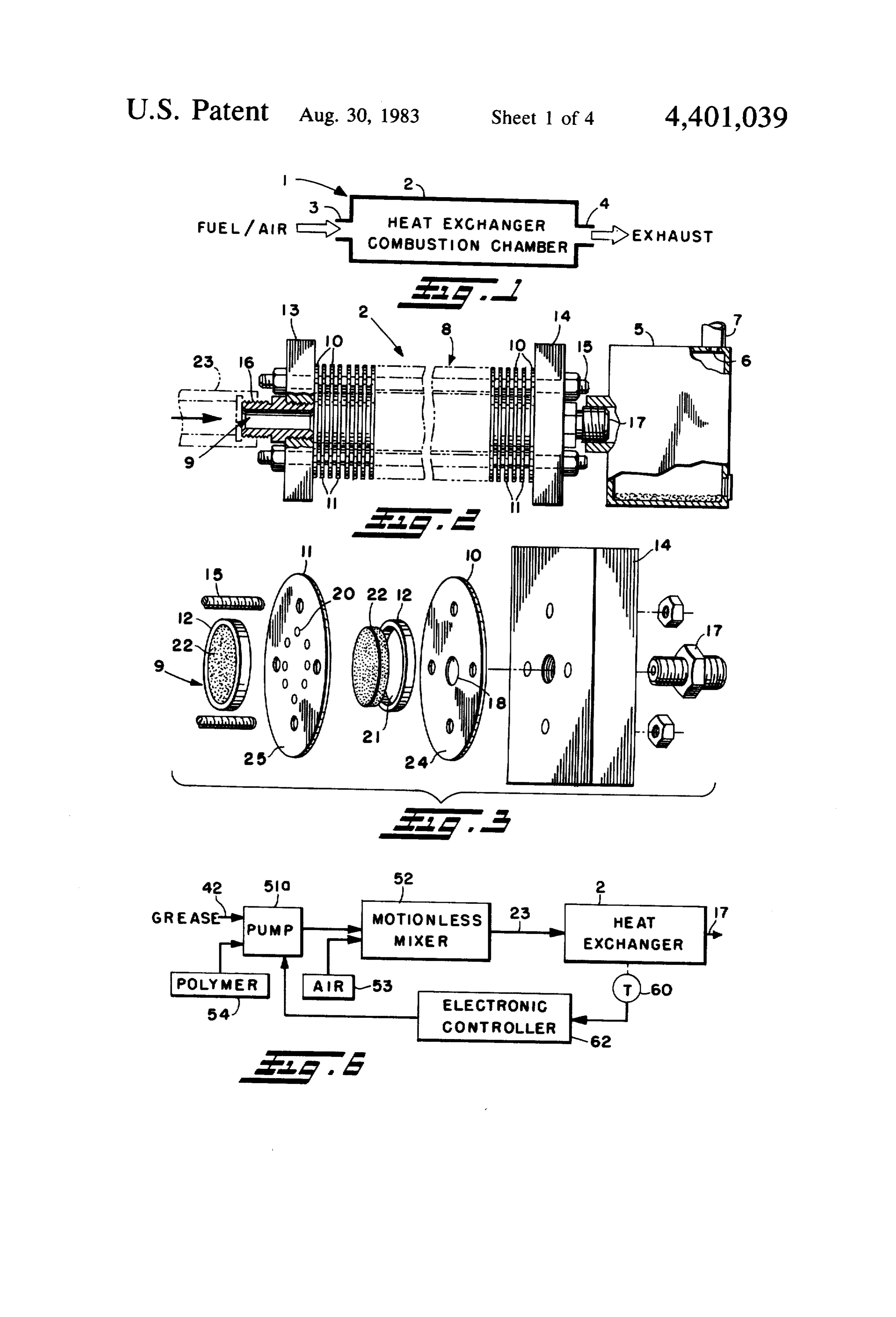
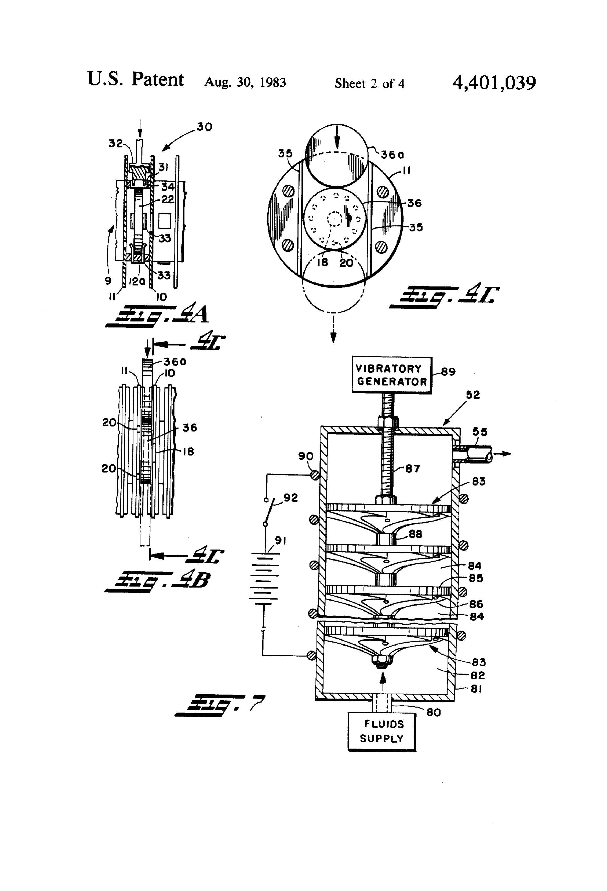
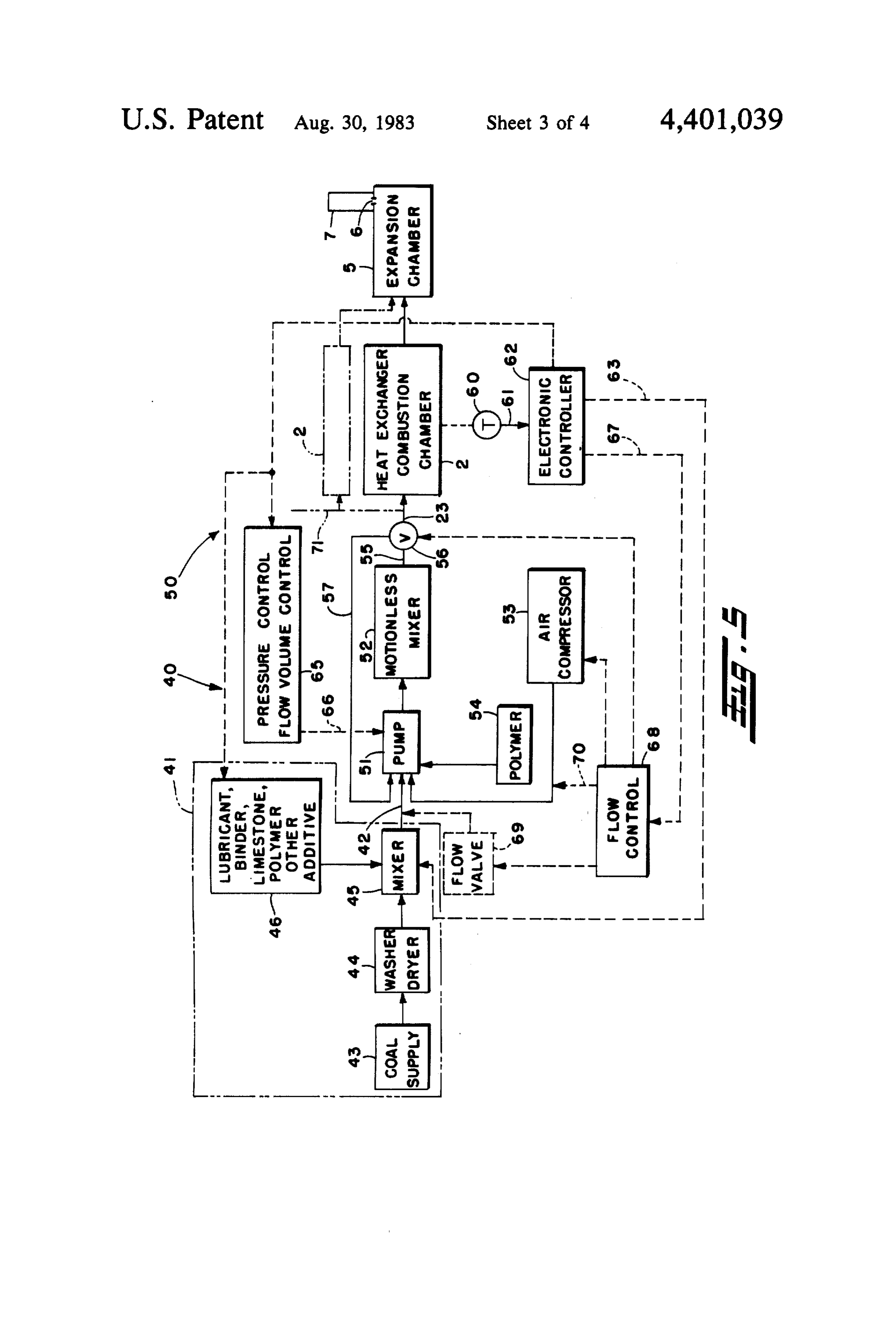
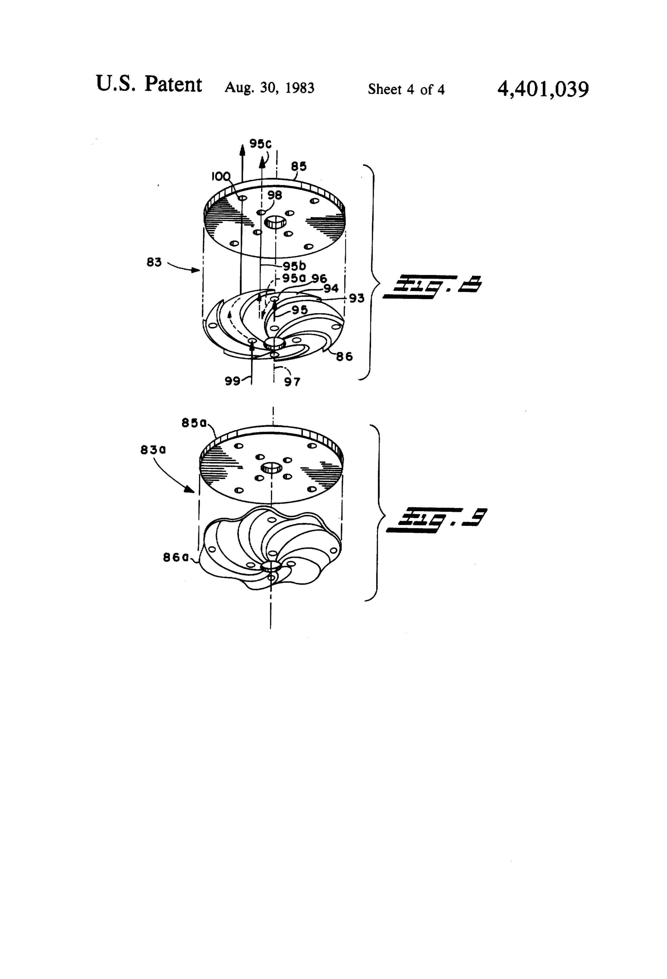
The particulate fuel may be prepared for combustion FIG. 7 is a side elevation partial section view of a by combining a fluid material with the fuel to form a motionless mixer for use in the invention; fluid-like mixture thereof and mixing air with the fluid FIG. 8 is an exploded view of a mixing element of like mixture to form a foam-like mixture or dispersion. such motionless mixer; and
The method of praparing and burning coal includes FIG. 9 is an exploded view of an alternate, but pre combining particulate coal with a petroleum or pe ferred, form of mixing element for the motionless mixer. troleum-like material capable of forming a mixture hav DETAILED DESCRIPTION OF INVENTION ing grease-like characteristics, mixing the grease-like mixture with air to form a foam-like dispersion mixture Referring in detail to the drawings, and initially to thereof, maintaining a relative pressure on the foam-like O FIGS. 1, 2 and 3, a combustion apparatus 1 in accor dispersion mixture substantially to maintain the relative dance with the present invention is illustrated. The dispersion of air and grease-like material, and effecting combustion apparatus 1 includes a heat exchanger com combustion of the foam-like mixture. bustion chamber 2 (for brevity referred to below some With the foregoing in mind, principal objects of the times as combustion chamber) preferably having a sub invention are to provide an improved process and to 15 stantially constant or otherwise controlled cross-sec provide an improved apparatus for combustion. tional open area. An inlet 3 permits fuel and air to enter Another object is to improve efficiency of a combus the combustion chamber 2, and an outlet 4 allows the tion process. exhaust products of combustion to exit the combustion An additional object is to reduce pollutants, including chamber. A heat exchanger function is an integral part gas and solid by-products of combustion. 20 of the combustion chamber 2 directly to remove the A further object is to improve efficiency with which heat of combustion from the interior to the external heat can be removed from a combustion process. environment of the combustion chamber. Still another object is to control effectively a continu A mixture of fuel and air is delivered continuously to ous combustion process. the combustion chamber 2. Such mixture preferably has Still an additional object is to prepare a fuel for com 25 the air well dispersed in the fuel which may be achieved bustion in an efficient manner minimizing handling and by first forming a foam-like dispersion of fuel and air, transport complexities. pumping the same through the inlet 3 into the combus Still a further object is to facilitate combustion of fuel tion chamber 2 at a pressure head and maintaining pres and use of the energy of combustion. surization within the combustion chamber 2 during the Even another object is to obtain the foregoing objects 30 combustion process. Such pressurization may be especially using coal as the fuel or a component thereof. achieved by maintaining substantially constant or other Even an additional object is to prepare a coal base wise controlled cross-sectional open area of the com fuel that can be pumped with minimum abrasion. bustion chamber, providing impediments to flow with These and other objects and advantages will become the combustion chamber, and, if desired, providing an more apparent as the following description proceeds. 35 outlet expansion chamber 5 (FIG. 2) with a flow con To the accomplishment of the foregoing and related trolling orifice 6 between the expansion chamber and ends, the invention, then comprises the features herein the stack 7 through which the exhaust gases ordinarily after fully described in the specification and particularly would flow and exit to the external environment. pointed out in the claims, the following description and In FIGS. 2 and 3 details of the heat exchanger com the annexed drawings setting forth in detail certain 40 bustion chamber 2 are illustrated. illustrative embodiments of the invention, these being Reference is made to co-pending, commonly owned indicative, however, of but several of the various ways U.S. patent application Ser. No. 148,022, filed May 8, in which the principles of the invention may be em 1980, entitled "Thermal Energy Transfer Apparatus ployed. and Method" which discloses the principles of con 45 struction and operation of a heat exchanger similar to
BRIEF DESCRIPTION OF DRAWINGS the heat exchanger combustion chamber 2 of the pres In the annexed drawings: ent invention. The disclosure of such co-pending patent FIG. 1 is a schematic representation of a heat ex application hereby is incorporated by reference. changer combustion chamber in accordance with the Fundamentally, the combustion chamber 2 may be present invention; 50 considered to have an external housing 8 and an internal FIG. 2 is a side elevation view, partly broken away in flow path 9 therethrough. The housing 8 is formed by a section, of the heat exchanger combustion chamber of plurality of thermally conductive plates or discs 10, 11, FIG. 1; separator rings 12, and end plates 13, 14, which are FIG. 3 is a fragmentary exploded view of the heat clamped together by fasteners 15. The flow path 9 is exchanger combustion chamber of FIG. 1; 55 formed by openings through the end plates 13, 14 in FIG. 4A is a fragmentary side elevation view, partly which inlet and outlet fittings 16, 17 are threaded se broken away in section, of a modified heat exchanger; curely, centrally located openings 18 in the discs 10 in combustion chamber; axial alignment with the inlet and outlet fittings 16, 17 FIGS. 4B and 4C are, respectively, a fragmentary along the axis 19 of the combustion chamber 2, openings side elevation view and an internal view looking in the 20 in the discs 11 spaced radially relative to the axis 19 direction of the arrows 4C-4C of FIG. 4B sharing a but within the circumference of the respective rings 12, further modified heat exchanger combustion chamber; and the hollow interiors 21 of such rings. Means, not FIG. 5 is a schematic system diagram of a fuel prepa shown, may be provided between rings 12 and discs 10 ration and burning system in accordance with the pres or 11 and between discs 10 and respective ends plates ent invention; 65 13, 14 to prevent fluid leakage between the flow path 9 FIG. 6 is a fragmentary schematic system diagram of and the external environment of the housing 8. The a modified fuel preparation and burning system in ac rings 12 accordingly provide chambers between discs cordance with the present invention; 10, 11 in which the foam-like or other material may mix 8 and may confront and transfer heat to the surface areas sure ordinarily to be maintained in the expansion cham of discs 10, 11 bounding the ring interior 21. In the ber 5 further opposing the noted pressure head. More preferred embodiment and best mode a thermally con over, the cooperation of expansion chamber 5 and ori ductive porous disc or medium 22 is positioned in the fice 6 helps to even out pressures in a parallel stream hollow interior of each ring 12. The ring is a holder for system with a common stack as shown simplifying the such disc 22. control procedure described below. Such cooperation In operation of the heat exchanger combustion cham also permits solid ash or other materials carried in the ber 2 a foam-like mixture of coal, air and possibly addi exhaust products of combustion to drop to the bottom tional additives or materials is delivered to the inlet of the expansion chamber 5 from which they can be fitting 16 via a tube or pipe 23 under a pressure head 10 removed effectively without uncontrolled discharge developed by an upstream pump, not shown in FIGS. 1 through the stack 7.
through 3. The disc most proximate the inlet end plate The constant or controlled cross-sectional area con 13 is the disc 10 having a central opening 18, which is sideration allows extruding of the burning mass through also the case with respect to the disc 10 adjacent the the combustion chamber 2. This provides a scrubbing outlet end plate 14; the discs 10, 11 otherwise are alter 15 action which aids in moving the ash through, into the nated along the axis 10. Accordingly, the main flow expansion chamber for facile removal therefrom. stream passing through the central opening 18 of the Efficient removal of heat from the heat exchanger first most upstream disc 10 must divide into multiple combustion chamber 2 by means of direct conduction flow streams radially spaced outwardly relative to the through the discs 10, 11 is achieved by the substantial axis 19 to pass through the openings 20 of the next area of such discs exposed within the flow path 9 as downstream disc 11; the multiple flow streams formed delimited by the area circumscribed by respective rings by the disc 11 then are merged or combined as the flow 12. The disc surface areas 24, 25 then transmit heat to through the opening 18 of the next downstream disc 10; the environment externally of the housing 8. and so on. As a result of such dividing and recombining The disc or waffers 22 may provide a plurality of of the material flowing through housing 8 there is an 25 functions. The discs 22 are porous to the material flow appreciable amount of mixing of such material maintain ing through the flow path 9 to the extent that such discs ing the homogeneity thereof and there also is a substan preferably help to disperse material flowing there tial amount of contact by such material with surfaces of through thereby to achieve continued dispersion of air the discs 10, 11 exposed in the flow path 9. Multiple in the mixture. The discs 22 also may have good thermal direction changes of the material flowing in flow path 9 30 energy conductive properties such that as combustion tends to impede flow therethrough to maintain continu occurs therein heat is transferred therethrough directly ous back pressure opposing the pressure head under by conduction at the surfaces thereof engaged with which the material is pumped and produces a head respective discs 10, 11 for conduction then via the discs pressure for the flame preventing flashback. In the 10, 11 to the external surface areas 24, 25 and the exter main, though, the sum of cross-sectional areas of radial 35 nal ambient environment. Furthermore, the discs 22 openings 20 in a disc 11 equals that of central opening 18 may be formed of a material that is degradable or chem in a disc 10 so that flow impedance is created by direc ically reactive with respect to the materials undergoing tion changes and stream dividing rather than by flow combustion or to affect such combustion and/or the restrictions. Generally the fill material, e.g. porous disc ultimate products of combustion; for example, the discs 22, also has an equivalent cross-sectional open area 22 may be formed at least in part of a limestone material relative to the principal direction of flow of material that reacts with sulphur in the coal to remove such therethrough. sulphur from the exhaust gases. The discs 10, 11 also Combustion of the material flowing through the com may be formed of such or other type of degradable bustion chamber 2 along the flow path 9 may be started material. As a result relatively high sulphur coal can be by conventional means, such as, for example, spark 45 burned with minimum sulphur pollution emitted to the ignition, glow wire ignition, or flame ignition, each of air without the need for expensive scrubbers and the which may gain access to the flow path 9 through an like. Alternatively, the discs 22 may be formed of metal opening, not shown, in the housing 8. Alternatively, mesh or of filter-like material, such as stainless steel. heat may be applied to surface areas 24, 25 of the discs which provides the desired dispersing and thermal con 10, 11 exposed to the external environment of the hous 50 ducting properties, for example, as is disclosed in the ing 8 outside the flow path 9, with such heat being above-mentioned co-pending application. conducted via one or more such discs to ignite combus It may be necessary to change the discs 22 relatively tion of the material in the flow path9; or other combus frequently with clean ones or with unreacted ones, i.e. tion igniting means may be used. unreacted with sulphur. In FIG. 4A is illustrated an With combustion commenced, combustion will con 55 access assembly 30 to facilitate gaining access to respec tinue ordinarily as long as the mixture of fuel and air is tive discs 22 within rings 12a without disassembling the supplied to the combustion chamber. During such con fasteners 15 and other components of the heat ex tinuing combustion the expanding gases produced by changer combustion chamber 2 housing 8. In the access such combustion further will create a back pressure assembly 30a hatch 31 in the ring 12a allows direct opposing the pressure head of the material pumped into access to the disc 22 when a hatch cover 32 is removed. the inlet fitting 16. The back pressure so created as well Fingers 33 near the bottom and sides of the ring 12a, as as the mixing in the flow path9 help to assure continued shown, and fingers 34 on the hatch cover center the disc retentive dispersion of air in the coal mixture of material flowing through the flow path for optimum efficiency 22 generally in parallel between the discs 10, 11. The fingers 34 also may be used to grasp the disc 22 for and completion of combustion within the flow path 9, 65 removal as the hatch cover 32 is removed and for di The exhaust products of combustion leave the flow path recting a new disc 22 into place. If desired, the access 9 via the outlet fitting 17 and enter the expansion cham assembly 30 may be modified such that approximately ber 5. The orifice 6 leading to the stack 7 causes a pres one-half of the ring 12a is entirely removable rather 9 than using the hatch 31 and hatch cover 32 approach; in only is partially dried. Moist coal is then mixed in . such modified arrangement the axial dimension of the conventional mixer 45, such as a screw type mixer or disc 22 may be such that it will engage surfaces of both the like with an additive from a supply 46. The additive discs 10, 11. preferably includes a pet roleum product binder, such as In FIGS. 4B and 4C is illustrated another embodi oil, which when mixed with the moist coal will form a ment to facilitate the replacement of discs 22 between grease-like substance provided to line 42. Moreover, the discs 19, 11 without disassembling the housing 8 of the additive may include linestone for removing sulphur combustion chamber 2. In such embodiment each disc from the exhaust products of combustion in the combus 10, 11 has tracks 35 thereon. An assembly 36 comprised tion chamber 2. Additionally, the additive may include of a ring 12 and a disc 22 is positioned between the pair O polymer that is a water scavenger and reacts therewith of tracks 35 on the disc 11 as well as between the pair of to help from the gell-like or grease-like consistency of tracks on the confronting disc 10 in position in the flow the material delivered to line 42. A disclosure of such path 9. A new assembly 36a may be positioned in readi polymer additive is in Goudy, Jr. U.S. patent applica ness relative to the tracks 35 and discs 10, 11 to be tion Ser. No. 06/08537, filed Dec. 31, 1979, which pushed down into the flow path 9 while ejecting the 5 application is not commonly assigned with the present original assembly 36 without interrupting the flow of application. The amounts of respective additives may be material and exhaust products of combustion through varied as desired, depending on the required end result the flow path 9 and without stopping the process of of material consistency, combustibility, sulphur or like combustion therein. The ejected assembly 36 may be removal and so on.
removed for recycling or for disposal, and a new assem 20 The system 40 also includes a final preparation, com bly 36a may be placed in position in readiness for the bustion and control stage 50. The preliminary prepara next change. tion stage 41 may be on the premises and on-line di It is contemplated that other means may be provided rectly with the stage 50, alternatively, the preliminary to replace discs 22 in the combustion chamber 2 prefera preparation stage 41 may be located elsewhere and the bly without diassembling the same. Thus, as the discs 25 grease-like material transported by conventional means become dirty with ash, otherwise chemically reacted or for delivery into line 42 which is the inlet to the stage used, etc., efficiency of the heat exchanger still may be 50.
maintained. In the final preparation, combustion and control stage In using the combustion chamber 2, then, it will be 50 the grease-like material in line 42 is pumped by a appreciated that a mixture of air and fuel, such as coal, 30 pump 51 into a motionless mixer 52, such as a motionless possibly plus additional additives, binders, lubricants, mixer generally of the type disclosed in co-pending, and so on, is delivered under a pressure head via the commonly assigned U.S. patent application Ser. No. tube 23 into the inlet fitting 16 and along the flow path 897,670, filed Apr. 19, 1978, U.S. Pat No. 4,259,021 9 of the housing 8. Combustion occurs continuously in which will be described summarily below. Air or a the flow path 9 and heat is removed from the flow path 35 direct supply of oxygen, if desired, also is delivered to to the environment externally of the housing 8 by con the pump 51 from an air compressor 53. Further, if duction through the discs 10, 11 which penetrate into desired, polymer, such as that mentioned above, may be the flow path and extend outside the housing 8. It is delivered to the pump from a polymer supply 54, the contemplated that the combustion will occur at a con polymer providing further water scavenging, oxygen trolled manner and by controlling the flow rate and 40 dispersion and entrapment in the mixture, and possibly pressure head of the material delivered into the combus other properties as well. As the material is pumped by tion chamber 2 the thermal energy, such as the Btu's the pump 51 through the motionless mixer 52 the air delivered via the discs 10, 11 and the temperature will become well dispersed in the grease-like material in thereof can be controlled. If desired, to increase the a manner such that the effluent at the output 55 of the total thermal energy obtained, plural combustion cham 45 motionless mixer 52 is of a foam-like or relatively homo bers 2 may be connected in fluid parallel relation, e.g. geneous consistency. A flow control valve 56 may be manifold from a common pump and supply of fuel/air operated to cause all, part of or none of the foam-like mixture therefor, thus increasing the total thermal en effluent to pass through to the line or tube 23 to a com ergy capacity of such system without changing the size bustion chamber 2 or to be fed back via a by pass line 57 of any individual combustion chamber 2. The outlet 50 to the pump 51. Thus, controlling the valve 56 or the fittings 17 of such parallel heat exchangers combustion pump 51 allows variation in the flow rate and pressure chambers may be connected to a common expansion of the foam-like effluent delivered to the combustion chamber 5 and stack 7 or to individual ones, as desired, chamber 2.
although the former case would be preferred to main The temperature or other parameter of the combus tain uniform pressure in all the combustion chambers. 55 tion chamber 2 may be monitored by one or more tem Turning now to FIG. 5, a system 40 for preparing and perature sensors 60, which may be mounted, for exam burning coal to other fuel is illustrated schematically. ple, on the surfaces 24 or 25 of one or more of the discs The system 40 includes a preliminary preparation stage 10, 11, and the electrical output 61 from such tempera 41, which may be of conventional equipment used to ture sensor(s) may be coupled to a conventional elec make and to deliver at line 42 a prepared coal material tronic controller 62, for example, that effects an analog having a grease-like consistency capable of being type control function. Digital control techniques also pumped with minimum abrasion and also being capable may be used. The electronic controller 62 is connected of facile transportation and handling in relatively clean by line 63 to control the mixer 45, such as the speed fashion. Coal from a supply 43, such as coal fines, pull thereof thereby controlling consistency of the grease verized coal, other particulate coal or the like, is 65 like material provided on line 42. Line 64 connects the washed and at least partially dried in a washer/dryer of controller 62 to the additive supply 46 for metering the conventional form 44. Clay and other materials accord additives delivered into the mixer 45. Line 64 also is ingly are washed from the coal and preferably the coal connected to a pressure control or flow volume control
Page 10scan →
65 which is connected in turn by line 66 to control 54 may be added, as shown in FIG. 6, for ultimate mix operation of the pump 51, and, therefore, the flow rate ing in the motionless mixer 52 with the grease-like coal or pressure of the material pumped through the motion material to form a foam-like effluent or output delivered less mixer 52 and, accordingly, the pressure head of the via line 23 to the combustion chamber 2 for combustion foam-like material delivered into the combustion cham 5 as above. The temperature sensor 60 and electronic ber 2. The control 65 also may be operated manually, if controller 62 control the displacement and speed of the desired, in convention manner. Further, the electronic pump 51 a thereby to control flow rate and pressure controller 62 may operate the control 65 to shut down head to the material delivered to the combustion cham the pump 51 in the event that a critical situation is ber 2.
sensed. Line 67 couples the electronic controller 62 to a O For optimum operation in either stage 50 or 50a as flow control 68, which may operate a flow valve 69 used in a system 40 in accordance with the present associated with line 42 to control the rate at which the invention, it is desired that the pressure head and flow grease-like material is delivered to the pump 51. The rate of the material delivered to the combustion cham flow control 68 also may control the valve 56 and oper ber 2 be adequate to maintain the desired temperature or ation of the air compressor 53 thereby controlling the 15 Btu output from the latter as well as to continue com flow output and pressure effected by the latter. Further bustion in the heat exchanger on a continuous basis. more, line 70 represents a valve type operational con Referring now to FIGS. 7 and 8, a motionless mixer trol of the air flowing between the air compressor 53 52 preferred in the present invention for dispersing air and the pump 51. in the grease-like material to produce a foam-like efflu In using the system 40 coal is prepared in the prelimi 20 ent at the mixer output 55 is illustrated. Fluids, such as nary preparation stage 41 to form a grease-like material the grease-like coal material and air are supplied under that may be conveniently and relatively cleanly handled pressure from the pump 51, compressed air generator with time and cost efficiency. Such material also may be 53, etc. to the inlet 80 of the motionless mixer 52. The efficiently combined with air for subsequent combus mixer housing 81 preferably is elongate and substan tion in the combustion chamber 2, which is closed to 25 tially completely encloses the interior volume 82 other external air supply, for achieving a continuous thereof except for the inlet 80 and outlet 55. A plurality combustion process. Heat removed from heat ex of mixing elements 83 and mixing chambers 84 therebe changer combustion chamber 2 may be used to do tween effect a dividing or separating function separat work, to effect space heating, and the like, as is well ing the inlet fluids into multiple streams, a direction known. Both safety and temperature control may be 30 changing function imparting location shifts and momen effected via the temperature sensors 60, electronic con tum to the individual streams, and a recombining of the troller 62 and the control lines and systems mentioned material from the streams thoroughly to mix the mate above. If desired, plural heat exchanger combustion rial ultimately producing the foam-like consistency chambers 2 may be connected in parallel, as is schemati which is delivered from the effluent outlet 55. Each cally represented in FIG. 5, and valve control means mixing element 83 may be formed by a flat plate-like may be placed in the manifold line 71 for allowing or disc 85 and a truncated conical disc 86. The discs 85, 86 cutting off flow of material for combustion in respective are mounted on a support rod 87 and are separated from combustion chambers under control of the electronic each other by spacers 88. A vibratory generator 89 may control 62 or by other means, now shown. apply vibratory energy via the support rods 87 to the Thus, the electronic controller 62 may be a speed mixing elements 83 further to facilitate mixing action, versus temperature analog control system. Information and, if desired, thermal energy may be applied to the may be fed into the electronic controller 62 relating to motionless mixer 52 via a conventional electric heating data on the grease-like material provided on line 42, coil 90 energized by a battery 91 upon closure of a such as whether the lubricant added to the coal is a switch 92.
number 1 oil, a number 2 oil, etc., the approximate 45 Details of construction and operation of the motion Sulphur content in the coal from the coal supply 43, and less mixer 52 are disclosed in the above-mentioned co so on, which information may be provided directly pending U.S. patent application Ser. No. 897,670. Sum from the supplier of the grease-like coal product. When marizing such operation, the fluids passing through inlet used in a complete on-line system with both preliminary 80 enter the housing 81 inlet chamber 82 and are caused and final stages 41, 50, electronic controller 62 also may SO under pressure to follow the curved walls 93 (FIG. 8) control the amount of additive delivered to mixer 45 and surfaces 94 of the conical disc 86. One flow stream from the additive supply 46 as a function of the material represented by arrow 95 enters a hole 96 in the conical of which the lubricant is formed, the size of the particu disc 86, such hole being spaced radially relatively re late coal from the coal supply 43, the wetness of the mote from the axis 97 of the mixer 52. A stream is material delivered from the washer/dryer 44, the sul 55 formed by the fluid flowing through the hole 96. That phur content of the coal, and possibly other informa stream follows the dashed arrow 95q in a curved direc t1On, tion inward toward the axis 97 until aligned with the Turning briefly to FIG. 6, a modified final prepara opening 98 in the flat disc 85. The stream follows line tion, combustion and control stage 50a which may be 95b through such opening 98, which is angularly shifted substituted in the system 40 for the stage 50 thereof is about the axis 97 and is radially shifted to a location illustrated. The modified stage 50a is simplified from more proximate the axis 97 that is the opening 96. Ac that shown in FIG. 5 because the pump 51a is capable of cordingly, the stream now has inparted thereto a cer direct control readily to control flow rate and head tain rotational inertia and exits through the opening 98 pressure; accordingly the pump 51a is a variable dis along the line 95c into the next downstream mixing placement and variable rate pump. Using the pump 51a 65 chamber 84. The line 99 represents another flow stream the valve 56 may be eliminated as may be other portions which begins at a location relatively proximate the axis of the control system illustrated in FIG. 5. Air from an 97, leaves the disc 85 at opening 100 relatively remote air compressor 53 and polymer from a polymer supply from the axis and has a rotational inertia spinning in the 11 opposite direction from that of the stream following the fuel and air therein, said dispersing means comprising line 95. The displacement of streams, the rotational dividing means for dividing a mixture of such fuel and inertia imposed on the streams and the shear effected by air into plural streams and combining means for recom the sharp edges of the walls 93 of the next downstream bining such streams, said combustion chamber compris conical disc and so on will effect a thorough mixing of 5 ing a housing with a flow path therethrough, said divid the material input to the motionless mixer 52. The de ing means comprising plate means for blocking flow sired consistency of the effluent with good and long and plural opening means in said plate means for passing term dispersion of air in the fuel can thus be obtained. respective streams therethrough, said combining means Referring briefly to FIG. 9, a modified combination comprising further plate means for blocking flow and of discs 85a, 86a, for use as mixing elements in a motion O one opening means therein for passing a recombined less mixer 52 are illustrated-these representing the flow stream therethrough, and means for holding said preferred embodiment and best mode of mixing element plate means and further plate means in said housing to believed useful in the motionless mixer for the desired position said plural and one opening means in said flow purpose of mixing a grease-like coal fuel and air. The path, and further comprising a porous medium means principal difference between the mixing element 83a is 15 positioned between respective relatively adjacent plate that the conical disc 86a does not have sharp walls 93; means and further plate means for further dispersing rather the transition between the various curved wall material flowing therethrough, sections of the conical disc is more wave-like to provide 3. A combustion apparatus, comprising a cornbustion a relatively smooth directional gradient thereacross. chamber, inlet means for permitting fuel and air to enter Such format will minimize the congestive accumulation 20 said combustion chamber, outlet means for permitting of material in the motionless mixer when the viscosity exhaust products of combustion to exit said combustion and abrasive characteristics are relatively high. On the chamber, and thermally conductive heat transfer means other hand, the truncated conical disc 86a is appreciably exposed inside and outside of said combustion chamber more difficult and expensive to manufacture relative to for transmitting heat by conduction from inside said the disc 86 and to that extent may be less preferred than 25 combustion chamber to the outside thereof, said com the disc 86. bustion chamber comprising a housing with a flow path STATEMENT OF INDUSTRIAL USE along which flows a mixture of fuel and air, in which combustion occurs, and along which flow the exhaust
With the foregoing in mind it will be appreciated that products of combustion, said heat transfer means com the heat exchanger combustion chamber 2, and motion 30 prising plate means having substantial surface areas less mixer 52 may be used in concert in a system 40 to thereof exposed directly in said flow path and further effect thorough and efficient preparation and combus substantial surface areas thereof exposed outside said tion of fuel while obtaining efficient thermal energy flow path to the environment outside said housing, and transfer characteristics to remove the heat from the said plate means having openings therein positioned in combustion chamber. Additionally, a facile and efficient 35 said flow path and forming a part thereof. control may be provided for controlling thermal energy 4. A combustion apparatus, comprising a combustion output. chamber, inlet means for permitting fuel and air to enter I claim: said combustion chamber, outlet means for permitting 1. A combustion apparatus, comprising a combustion exhaust products of combustion to exit said combustion chamber, inlet means for permitting fuel and air to enter 40 chamber, and thermally conductive heat transfer means said combustion chamber, outlet means for permitting exposed inside and outside of said combustion chamber exhaust products of combustion to exit said combustion for transmitting heat by conduction from inside said chamber, and dispersing means in said combustion combustion chamber to the outside thereof, said com chamber for controllably dispersing a mixture of such bustion chamber comprising a housing with a flow path fuel and air therein, said dispersing means comprising 45 along which flows a mixture of fuel and air, in which dividing means for dividing a mixture of such fuel and combustion occurs, and along which flow the exhaust air into plural streams and combining means for recom products of combustion, said heat transfer means com bining such streams, said combustion chamber compris prising plate means having substantial surface areas ing a housing with a flow path therethrough, said divid thereof exposed directly in said flow path and further ing means comprising plate means for blocking flow 50 substantial surface areas thereof exposed outside said and plural opening means in said plate means for passing flow path to the environment outside said housing, and respective streams therethrough, said combining means further comprising dispersing means in said combustion for comprising further plate means for blocking flow chamber for controllably dispersing a mixture of such and one opening means therein for passing a recom fuel and air therein, said dispersing means comprising a bined flow stream therethrough, and means for holding 55 porous medium means positioned in said flow path for said plate means and further plate means in said housing dispersing material flowing therethrough, said dispers to position said plural and one opening means in said ing means comprising thermally conductive material flow path, said plate means comprising thermally con and having surface areas in thermally conductive en ductive heat transfer means exposed inside and outside gagement with said substantial surface areas of said of said combustion chamber for transmitting heat by 60 plate means.
conduction from inside said combustion chamber to the 5. A combustion apparatus, comprising a combustion outside thereof. chamber, inlet means for permitting fuel and air to enter 2. A combustion apparatus, comprising a combustion said combustion chamber, outlet means for permitting chamber, inlet means for permitting fuel and air to enter exhaust products of combustion to exit said combustion said combustion chamber, outlet means for permitting 65 chamber, and flow directing means for directing the exhaust products of combustion to exit said combustion flow of fuel and air in said combustion chamber, said chamber, and dispersing means in said combustion flow directing means comprising means for chemically chamber for controllably dispersing a mixture of such lowering the quantity of at least one material in the 12 exhaust products of combustion, said combustion cham 14. The apparatus of claim 12, said means for main ber comprising a housing, and a substantially closed taining comprising pump means for applying a pressure flow path in said housing leading from said inlet means head to such mixture for delivery under pressure to said to said outlet means and along which a mixture of fuel combustion chamber.
and air flows, in which combustion occurs, and along 5 15. The apparatus of claim 14, said means for main which exhaust products pass, and said flow directing taining comprising means for maintaining substantially means being positioned in said flow path, said flow continuous constant pressure on such mixture, said directing means comprising a porous medium, and fur combustion chamber comprising a substantially closed ther comprising means for changing said porous me substantially constant, or otherwise controlled cross dium, said means for changing comprising guide means to sectional open area, chamber having a flow path there for serially guiding insertion of one porous medium into through between an inlet thereto and an outlet there said flow path while ejecting another porous medium from, and said means for maintaining further compris from said flow path, and further comprising dispersing ing pump means for pumping a mixture of fuel and air at means in said combustion chamber for controllably a pressure head and in said combustion chamber for dispersing a mixture of such fuel and air therein, said 5 impeding flow of such mixture therethrough. dispersing means including dividing means for dividing 16. The apparatus of claim 12, said combining means the mixture of fuel and air into plural streams and com comprising means for washing and at least partially bining means for recombining such streams, said divid drying the coal.
ing means comprising plate means for blocking flow 17. The apparatus of claims 13 or 16, further compris and plural opening means in said plate means for passing 20 ing means for adding polymer to such mixture. respective streams therethrough, said recombining 18. The method of claim 6, said combining compris means comprising further plate means for blocking flow ing combining coal with a petroleum or petroleum-like and one opening means therein for passing a recom product.
bined flow stream therethrough, means for holding said 19. The method of claim 18, said combining compris plate means and said further plate means in said housing ing combining polymer in such emulsion. to position said plural and one opening means in said 25 20. The method of claim 18, said combining compris flow path, and said guide means comprising guide track ing combining limestone in such emulsion. means on said plates. 21. The method of claim 6, said mixing comprising 6. Method of combustion of a fuel, comprising mixing effecting such mixing in a motionless mixer. air with such fuel to form a foam-like material, and 22. The method of claim 6, said mixing comprising effecting substantially continuous combustion of such 30 pumping fuel through a mixing apparatus and in the foam-like material while maintaining at least partial mixing apparatus dispersing air in the fuel. relative pressurization thereof, and further comprising 23. The method of claim 6, said effecting comprising combining a particulate fuel with a further material to effecting combustion in a substantially closed, substan form a fluid-like emulsion thereof, and said mixing com tially constant, or otherwise controlled cross-sectional prising mixing air with such emulsion. 35 open area, combustion chamber having an inlet to re 7. The apparatus of claims 1 or 2, wherein the sum of ceive such foam-like material and an outlet to discharge cross-sectional areas of said plural opening means in one the exhaust products of combustion. of said plate means is approximately equal to the cross 24. The method of claim 6, said effecting comprising sectional area of said one opening means in one of said effecting combustion in a combustion chamber, and further plate means. 40 further comprising controlling at least one of the flow 8. The apparatus of claims 1 or 2, said plate means rate and pressure of such foam-like material supplied to comprising a plurality of the same, and said further such combustion chamber thereby to control combus plate means comprising a plurality of the same, said tion in such combustion chamber.
plate means and further plate means being positioned in 25. Method of preparing particulate fuel for combus alternating sequence in said flow path. 45 tion, comprising combining a fluid material with such 9. The apparatus of claim 2, said porous medium fuel to form a fluid-like mixture thereof, and mixing air comprising means for chemically lowering the quantity with said fluid-like mixture to form a foam-like mixture. of at least one material in the exhaust products of com 26. The method of claim 25, said combining compris bustion. ing combining coal and a petroleum or petroleum-like 10. The apparatus of claim 3, said plate means com product.
prising dividing means for dividing a mixture of the fuel 27. The method of claim 25, said combining further and air into plural streams and combining means for comprising combining polymer in such fluid-like mix recombining such streams. tre.
11. The apparatus of claim 5, said flow directing 28. The method of claim 25, said mixing comprising means comprising limestone and such one material com mixing in a motionless mixer.
prising sulphur in the exhaust gas. 55 29. The method of claim 28, further comprising ap 12. Apparatus for preparing and burning coal, com plying a pressure head to such fluid-like mixture to urge prising combining means for combining particulate coal the same and air through such motionless mixer. with a petroleum or petroleum-like material to form a 30. Method of preparing and burning coal, compris mixture having grease-like characteristics, mixing ing combining particulate coal with a petroleum or means for mixing such grease-like mixture with air to 60 petroleum-like material capable of forming a mixture form a foam-like dispersion mixture thereof, means for having grease-like characteristics, mixing such grease maintaining a relative pressure on such foam-like dis like mixture with air to form a foam-like dispersion persion mixture to retain the relative dispersion of coal mixture of such grease-like mixture and air, maintaining and air thereof, and combustion chamber means for a relative pressure on such foam-like dispersion mixture providing an environment for controlled combustion of 65 substantially to maintain the relative dispersion of air such coal and air of such foam-like dispersion mixture. and grease-like material, and effecting combustion of 13. The apparatus of claim 12, said mixing means such foam-like dispersion mixture.
comprising a motionless mixer. sh -k k t sk
Provenance
- Collection
- Patents citing this work
- Pages
- 12
- Method
- pdftotext (the PDF's own text layer) + pdftoppm 300dpi page scans
- Patent office record
- patents.google.com →
- Source
- Google Patents citing-documents table
- Assignee
- Goudy Jr Paul R
- Published
- 1983-08-30
- Transcribed from
- patentimages.storage.googleapis.com →