

patent · US4452214A
Fuel mixing device
5 June 1984
Text
Page 1bibliographic recordscan →
United States Patent (19)
Dah
54 FUELMIXING DEVICE
75 Inventor: Byron M. Dahl, Watertown, S. Dak.
73 Assignee: Fuel Efficiency Co., S. Dak.
Int. Cl. ............................................. FO2M 17/26 52 U.S. Cl. .................................... 123/523; 123/524;
712,542 11/1902 Jeffery ................................. 123/524
1,261,230 4/1918 Haynes et al. ...................... 123/523 1,882,318 11/1932 Curioni ............................... 123/523 1,885,697 11/1932 Fabbro ................................ 23/592
Primary Examiner-Ira S. Lazarus
Assistant Examiner-E. Rollins Cross
Attorney, Agent, or Firm-Dorsey & Whitney
A fuel mixing device is provided an more particularly on improved fuel mixing device for an internal combus tion engine which improves the fuel efficiency of the engine to obtain a more complete utilization of the power transmitting properties of the fuel.
16 Claims, 4 Drawing Figures
Drawings
Page 2drawing sheetscan →
Page 3scan →
the hydrogen is supplied downstream from the atomiza
FUEL MXNG DEVICE tion chamber, but upstream of the butterfly valve or other throttling device for metering the air/fuel mixture
BACKGROUND OF THE INVENTION into the combustion chambers. In the preferred embodi The present invention relates generally to a fuel mix ment, the source of hydrogen is provided by a plurality ing device, and more particularly to an improved fuel of plates immersed in a soda water bath and connected mixing device for an internal combustion engine which with the leads of a five volt regulator. improves the fuel efficiency of the engine to obtain a It has been found that the above invention dramati more complete utilization of the power transmitting 10 cally improves the fuel efficiency of an internal combus properties of the fuel. tion engine and under certain conditions has improved A great number of fuel mixing devices or carburetors such efficiency as much as two or three fold. Addition for internal combustion engines exist in the prior art. ally, it is believed that emissions from an engine utilizing Many of these have been designed to increase the fuel the device of the present invention will pass pollution effieiency of an internal combustion engine usable in an control specifications, thus eliminating the need for a automobile. Such design efforts have been increased in 15 catalytic converter.
recent years due primarily to the shortage of gasoline Accordingly, an object of the present invention is to and other petroleum based fuels. Although these at provide an improved fuel mixing device for an internal tempts have resulted in fuel mixing devices with some combustion engine.
increase in fuel efficiency, none of these devices has led 20 Another object of the present invention is to provide to a carburetor design in which, under certain condi a fuel mixing device for an internal combustion engine tions, the fuel efficiency can be increased as much as having improved fuel atomization means. two or three fold.
Accordingly, there is a need in the art for an im a fuel mixingobject
A further device of the present invention is to provide for an internal combustion engine proved fuel mixing device or carburetor for an internal in which the atomization means includes a rotatable combustion engine capable of dramatically improving 25 drum having a porous screen-like or filter-like side wall. the fuel efficiency of such engine. Another object of the present invention is to provide SUMMARY OF THE INVENTION a fuel mixing device for an internal combustion engine The present invention relates to an improved fuel having means for supplementing the air/fuel mixture mixing device for an internal combustion engine which 30 with a small amount of hydrogen.
includes a means for improving the atomization and A still further object of the present invention is to vaporization, and thus the efficiency of the fuel. Part of provide a fuel mixing device for an internal combustion the increase in fuel efficiency results from an improved engine comprising an improved atomization means in atomization device and part from the utilization of combination with a means for supplementing the air/fwarm air from the manifold of the engine for use as 35 uel mixture with hydrogen.
atomizing or vaporizing air. The device of the present Another object of the present invention is to provide invention also includes means for supplementing the a fuel mixing device for an internal combustion engine air/fuel mixture provided to the power cylinders with a including means for utilizing warm air from the mani small supply of hydrogen. It has been found that this fold to improve atomization of the fuel. supply of hydrogen, both by itself, but also particularly 40 These and other objects of the present invention will in combination with the improved atomization means become apparent with reference to the drawings, the results in dramatic improvement in the fuel efficiency of description of the preferred embodiment and the ap an internal combustion engine. pended claims.
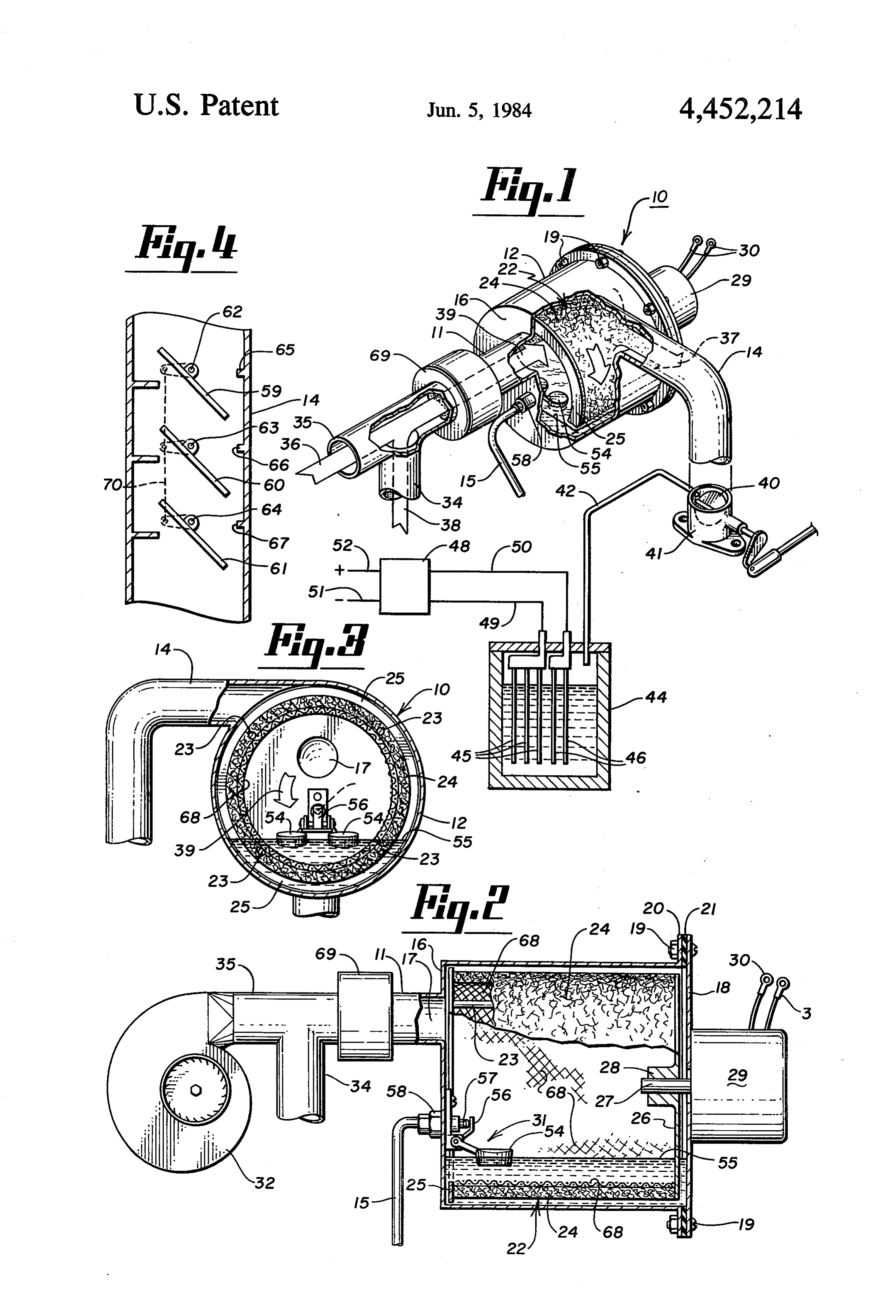
More specifically, the structure of the present inven tion includes a stationary fuel atomization chamber and 45 DESCRIPTION OF THE DRAWINGS a rotatable atomization drum disposed within this cham FIG. 1 is a pictorial view, with sections broken away, ber. The atomization drum is adapted for rotation about of the fuel mixing device of the present invention. its longitudinal or axial axis. The drum includes a hol FIG. 2 is a view, partially in section, showing the low interior and a side wall comprised of a porous, interior of the atomization chamber of the fuel mixing screen-like or filter-like material. Valve means are pro 50 device of the present invention. vided for maintaining a level of fuel within the fuel FIG. 3 is a view, partially in section, as viewed along atomization chamber sufficient to cover or contact at the section line 3-3 of FIG. 2. least a portion of the porous side wall of the rotatable FIG. 4 is a cross-sectional view of a portion of the atomization drum. As the drum is rotated, the liquid fuel conduit for directing the air/fuel mixture to the com becomes entrained in the porous side wall and is ex 55 bustion chambers of the engine. posed to incoming, atomization air as the drum rotates out of the fuel supply. Means is also included in the DESCRIPTION OF THE PREFERRED device of the present invention for providing a supply EMBODIMENT of atomizing air to the interior of the rotatable atomiz With general reference to FIGS. 1, 2 and 3, the fuel ing drum. In one embodiment of the present invention, mixing this means includes a means for directing warm air from generallydevice by of the present invention is illustrated the reference numeral 10. This device the engine manifold to the interior of the atomizing includes an atomizing chamber 12, a means 11 for sup drum as atomizing air. This warm air improves the atomization and vaporization of the fuel and thus in plying atomizing air to the chamber 12, a means 15 for proves the efficiency of the engine. 65 supplying fuel to the atomizing chamber 12 and a con The device of the present invention also includes a duit 14 for directing the air/fuel mixture from the cham means for supplementing the air/fuel mixture with a ber 12 to the combustion chambers of a conventional small supply of hydrogen. In the preferred embodiment, internal combustion engine.
Page 4scan →
The atomizing chamber 12 comprises a generally in the side wall as it is rotated through the supply of horizontally disposed cylindrical housing member hav gasoline or other fuel in the bottom of the chamber 12. ing a cylindrically shaped side wall and a pair of end Although it is contemplated that a variety of different walls 16 and 18 disposed generally parallel with respect types of materials could be used for the side wall 24, the to each other and at right angles with respect to the side preferred embodiment of the present invention contem wall. As illustrated best in FIG. 2, the end wall 16 is plates a filter or mesh type of material comprising a integrally formed with the side wall, whereas the end synthetic polyethylene fiber matte material supported wall 18 is connected with the side wall and thus the by a galvanized screen 68 having approximately a one main body of the chamber 12 by a plurality of screw or quarter inch mesh. This filter or mesh material in the rivet members 19. To facilitate the connection of the O preferred embodiment is approximately one quarter of end wall 18 to the chamber 12, the side wall of the an inch thick. Such thickness causes the atomizing air to chamber 12 includes an outwardly extending flange pass through the side wall 24 in a generally circuitous portion 20 adapted to mate and connect with the end path to increase the atomization and vaporization of the wall 18. A sealing gasket 21 is disposed between the fuel. Accordingly, the side wall 24 should be suffi flange 19 and the end wall 18 to provide a seal between 15 ciently thick to direct the atomizing air in a circuitous these two elements. In the preferred embodiment, the path. The filter or mesh material of the preferred em gasket 21 is constructed of a cork base or some other bodiment has openings of approximately 40/1000 of an material which is resistent to gasoline. inch.
Disposed within the atomizing chamber 12 is a rotat Although the preferred embodiment shows the atom able atomizing drum 22. The atomizing drum 22 in 20 izing drum 22 as being a hollow cylindrical structure, it cludes a cylindrically shaped side wall 24, a peripheral is contemplated that drums of other shapes could also flange portion 25 extending radially outwardly from an be utilized to obtain the advantages, of the present in open end of the side wall 24, an end wall 26 connected vention. For example, a cone-shaped or frusto, cone with a portion of the side wall 24 and extending in shaped drum could be utilized. With a structure of this wardly to a centrally disposed hub 28 and a plurality of 25 sort, it would be preferable for the level of gasoline in support rods 23 extending between the flange 25 and the the chamber 12 to be sufficiently high to cover at least end wall 26 to support the side wall 24. one full length of the side wall or to have the longitudi As illustrated best in FIG. 2, the hub 28 is connected nal axis of the conical drum tilted to achieve the same with an output shaft 27 of an electric motor 29. The result.
shaft 27 extends from the motor 29 and through the end 30 As shown best in FIGS. 2 and 3, the flange portion 25 wall 18 to connect with the hub 28. The elecric motor of the atomizing drum 22 extends radially outwardly is a conventional electric motor powered by a 12 volt from the open end of the side wall 24. The function of automobile battery (not shown). This is provided to the this flange 25 is to support the side wall 24 and to also motor 29 by appropriate connection with the electrical prevent air from leaking between the flange 25 and the leads 30, 30. Actuation of the motor 29 causes rotation 35 inner surface of the chamber, 12. To accomplish this of the shaft 27 and the hub 28, and thus corresponding latter function, it is preferable for the outer peripheral rotation of the inner atomizing drum 22 in the direction edge of the flange 25 to be closely, aligned with the of the arrow 39. In the preferred embodiment, the interior cylindrical surface of the chamber 12. Such a motor 29 drives the drum 22 at the rate of about thirty structure forces the atomizing air to flow outwardly revolutions per minute. through the mesh or filter type material of the side wall The fuel mixing device 10 of FIG. 1 also includes 24 as indicated in FIG. by the directional arrow 37. means for providing a supply of gasoline to the atomiza The end wall 16 of the atomizing chamber 12 includes tion chamber 12. This means includes the conduit 15 an opening 17 for communication with a conduit means and the valve assembly 31 (FIG. 2). The valve assembly 11 for providing a source of atomizing air to the interior 31 includes a conventional float/needle valve arrange 45 of the drum 22. The means 11 includes a conduit or ment in which the float elements 54 (FIGS. 1, 2 and 3) tubular section extending from a conventional squirrel of a float valve float on the level of gasoline 55 main cage fan 32 (FIG. 2) or other similar air supplying tained within the chamber 12. The float valve includes means and a conduit 34 for providing air from a second a tab portion 56 which engages a needle valve 57 to source. In the preferred embodiment, it is contemplated control the supply of gasoline to the chamber 12. As the 50 that the air provided through the conduit 34 would be level of gasoline 55 falls, the floats 54 also fall, thus warm or hot air taken from the manifold of the operat causing disengagement between the tab 56 and the nee ing internal combustion engine. It has been found that dle valve 57 and resulting flow of gasoline or other fuel this warmed air used as atomizing air in combination into the chamber 12. As the level of gasoline 55 rises, with the specific atomizing means of the present inven the floats 54 also rise, thus causing engagement between 55 tion significantly improves the atomization of the fuel. the tab 56 and the needle valve 57. This engagement As shown in FIG. 1, the air provided from the conven stops the flow of gasoline into the chamber 12. The tional fan means such as the squirrel cage fan 32 (FIG. needle valve 57 and the supply conduit 15 are con 2) is indicated by the directional arrow 36 while the air nected by an appropriate connection 58. The level of provided from the engine manifold is indicated by the gasoline 55 maintained in the chamber 12 should be 60 directional arrow 38. The two sources of air are com sufficient to cover a portion of the side wall 24 of the bined together and pass through a filter 69 within the atomizing drum 22. In the preferred embodiment, gaso conduit means 11, thereby resulting in a flow through line having a depth of about one and one-half inches is the opening 17 indicated by the directional arrow 39. maintained in the nine inch diameter chamber 12. As This atomizing air is directed through the open end of illustrated in FIG. 2, the level 55 covers a full length of 65 the atomizing drum 22 and into the interior of such a portion of the side wall 24. drum where it is forced through the meshed side wall The side wall 24 is constructed of a filter or mesh type 24. As the air passes through the side wall 24, it atom of material which enables gasoline to become entrained izes and causes the evaporation of gasoline entrained in 5 the side wall 24. It has been found that this structure with the baffle plates 59, 60 and 61 to limit the rotation results in a very complete and thorough atomization of the plates relative to the pins 62, 63 and 64. The pins and vaporization of the gasoline and thus results in 62, 63 and 64 are offset from the centers of their respec greater fuel efficiency. This air/fuel mixture is then tive plates 59, 60 and 61 to allow the plates to hang at an directed by the conduit 14 to the throttle valve 40 (FIG. angle as shown in FIG. 4. As can be seen the baffle 1) of an internal combustion engine. In the preferred is plates 59, 60 and 61 will allow flow of air downwardly embodiment, the throttle valve 40 comprises a conven as shown in FIG. 4, but will prevent flow in the oppo tional butterfly valve which controls the flow of the site direction caused by a blast or back fire. The plates air/fuel mixture to the combustion chambers. The bot 59, 60 and 61 are joined together by the rod 69 which tom end of the conduit 14 is connected with a baseplate 10 causes them to pivot together.
41 for further connection to the manifold leading to the Although the description of the preferred embodi combustion chambers. It should be noted that the upper ment has been quite specific, it is contemplated that end of the conduit 14 extends tangentially and horizon various changes could be made without deviating from tally outwardly from the top of the chamber 12 through the spirit of the present invention. Accordingly, it is an opening in the chamber 12. This relationship be 15 intended that the scope of the present invention be tween the conduit 4 and the chamber 12 is best illus dictated by the appended claims rather than by the trated in FIGS. 1 and 3. It should also be noted that description of the preferred embodiment. rotation of the drum 22 is in the direction of the arrow I claim:
39 to assist the airflow through the side wall 24 and into 1. A fuel mixing device for producing an air/fuel the conduit 14. 20 mixture for use in the combustion chambers of an inter As shown in FIG. 1, immediately upstream from the nal combustion engine comprising:
throttle valve 40 and disposed within the tube 14 is a a fuel atomization chamber; conduit 42 for supplying a small amount of hydrogen to a rotatable atomization drum disposed within said the air/fuel mixture. This conduit 42 is connected with fuel atomization chamber and adapted for rotation and extends from a container 44 which contains means 25 about its axial axis, said atomization drum having a for providing a supply of hydrogen. In the preferred side wall comprised of a porous, mesh-like material embodiment, the container contains a soda bath com and forming a closed side wall loop around said prising water and sodium carbonate (baking soda) and a axial axis;
plurality of metal plate electrodes 45, 45, 45 and 46, 46. means for rotating said atomization drum; The plates 45, 45, 45 are connected to the positive pole 30 means for maintaining a level of fuel within said fuel 49 of a five volt source 48 while the plates 46, 46 are atomization chamber sufficient to contact at least a connected with the negative pole 50 of the five volt portion of the side wall of said rotatable atomiza source 48. The five volt source 48, in the preferred tion drum; and embodiment, comprises a conventional five volt regula means for directing a supply of atomizing air to the tor which is connected with the leads 51 and 52 of a 35 interior of said closed side wall loop and through conventional car battery. When current is provided to said side wall to produce said air/fuel mixture. the five volt regulator 48 and thus into the solution 2. A fuel mixing device for producing an air/fuel within the container 44, hydrogen gas is produced by mixture for use in the combustion chambers of an inter electrolysis. This hydrogen gas is directed by the con nal combustion engine comprising:
duit 42 to the conduit 14 where it is mixed with the 40 a fuel atomization chamber;
air/fuel mixture. It has been found that supplementing a rotatable atomization drum disposed within said the air/fuel mixture with a small amount of hydrogen in fuel atomization chamber and adapted for rotation the manner illustrated in FIGS. 1 and 2 results, both by about its axial axis, said atomization drum having a itself, but also in combination with the improved atom side wall comprised of a porous, mesh-like mate izing means described above, in a significant increase in 45 rial;
fuel efficiency. This in turn leads to a dramatic increase means for rotating said atomization drum; in the miles per gallon obtainable by an automobile means for maintaining a level of fuel within said fuel utilizing the features of the present invention. atomization chamber sufficient to contact at least a Although it is contemplated that other means could portion of the side wall of said rotatable atomiza be used as a source of hydrogen, electrolysis of the 50 tion drum;
caustic soda bath or some other solution which will means for directing a supply of atomizing air to the produce hydrogen is preferred. In the preferred em interior of said rotatable atomizing drum and bodiment, the container 44 is approximately a one-half through said side wall to produce said air/fuel gallon container. Initially, water is added to this con mixture; and tainer 44 with a couple teaspoons of household baking 55 a conduit means connected with said fuel atomization soda. It has been found that this produces a sufficient chamber for directing said air/fuel mixture from supply of hydrogen which, in the preferred embodi said chamber to a throttle valve. ment, is less than about 10% of the air/fuel mixture and 3. The fuel mixing device of claim 2 including hydro preferably about 5%. The solution in the container 44 is gen supply means connected with said conduit means supplemented, when needed, by additional baking soda 60 for supplementing said air/fuel mixture with hydrogen. and/or water. 4. The fuel mixing device of claim 3 wherein said As illustrated in FIG. 4, check valve means are also air/fuel mixture is supplemented with less than about provided to prevent an engine back fire from entering 10% hydrogen.
the atomization chamber 12. This means includes the 5. The fuel mixing device of claim 4 wherein said three baffle plates 59, 60 and 61 which are pivotally 65 hydrogen supply means includes electrolysis means for supported by the pivot pins 62, 63 and 64 extending generating said supply of hydrogen.
horizontally across a vertical portion of the conduit 4. 6. The fuel mixing device of claim 5 wherein said Corresponding stop tabs 65, 66 and 67 are associated electrolysis means includes a soda bath.
Page 6scan →
7. The fuel mixing device of claim 2 wherein said 14. The fuel mixing device of claim 1 wherein said conduit means includes a horizontally disposed section means for maintaining a level of fuel within said fuel tangentially connected with the top of said atomization atomization chamber includes a float/valve means. chamber. 15. The fuel mixing device of claim 1 wherein said means for directing a supply of atomizing air to the 8. The fuel mixing device of claim 7 wherein said interior of said atomizing drum includes means for di conduit means includes a vertically disposed section recting warm air from said engine manifold to the inte and wherein said fuel mixing device includes a check rior of said atomizing drum.
valve means preventing the upward flow of air through 16. A fuel mixing device for producing an air/fuel said vertically disposed section. O mixture for use in the combustion chambers of an inter 9. The fuel mixing device of claim 1 wherein said nal combustion engine comprising:
atomization chamber is generally horizontally disposed. a fuel atomization chamber; 10. The fuel mixing device of claim 9 wherein said an atomization member disposed within said fuel atomization drum is cylindrically shaped and is rotat atomization chamber, said atomization member able about its longitudinal axis. 15 defining an interior chamber and having a side wall 11. The fuel mixing device of claim 10 wherein the portion comprised of a porous, mesh-like material longitudinal axis of said atomization drum is horizon and forming a closed side wall loop; tally disposed. means for maintaining a level of fuel within said fuel atomization chamber sufficient to contact said side 12. The fuel mixing device of claim 1 wherein said 20 wall portion of said atomization member; side wall is constructed of a porous synthetic fiber mate means for causing movement of said side wall portion rial having sufficient thickness to permit passage of said into, through and out of said level of fuel main atomizing air through said side wall only along a gener tained within said fuel atomization chamber; and ally circuitous path. means for causing the movement of atomizing air to 13. The fuel mixing device of claim 12 wherein said 25 the interior of said side wall loop and through said side wall is constructed of a synthetic polyethylene side wall portion to produce said air/fuel mixture. fiber.
Provenance
- Collection
- Patents citing this work
- Pages
- 6
- Method
- pdftotext (the PDF's own text layer) + pdftoppm 300dpi page scans
- Patent office record
- patents.google.com →
- Source
- Google Patents citing-documents table
- Assignee
- Fuel Efficiency Co.
- Published
- 1984-06-05
- Transcribed from
- patentimages.storage.googleapis.com →