

patent · US4408983A
Recuperative burners
11 October 1983
Text
Page 1bibliographic recordscan →
United States Patent (19)
Masters et al.
(54) RECUPERATIVE BURNERS
Inventors: Jeffrey Masters; Manjit S. Saimbi, both of Solihull; Roger J. Webb,
Redditch, all of England Assignee: British Gas Corporation, London,
England
(30) Foreign Application Priority Data
Aug. 29, 1980 GB United Kingdom ................. 802797O Int. Cl. .............................................. F23D 11/44 52 U.S. Cl. ..................................... 431/116; 431/215
2,857,961 10/1958 Brown ................................. 431/116 3,174,526 3/1965 Von Linde .......................... 431/116 3,269,448 8/1966 Martin ................................. 431/116 3,695,816 10/1972 Oeppen ............................... 431/215 3,705,784 12/1972 Reichhelm .......................... 431/116
3,826,083 7/1974 Brandon .............................. 431/16 3,869,244 3/1975 Von Linde. ... 431/116 4,230,445 10/1980 Janssen ....... ... 431/16 4,255,122 3/1981 Alpkvist .............................. 431/25
FOREIGN PATENT DOCUMENTS
52-18233 10/1977 Japan ................................... 431/16
Primary Examiner-Daniel J. O'Connor
Attorney, Agent, or Firm-Larson and Taylor
The invention is a recuperative burner, with heat ex change between the exhausting combustion products and incoming combustion air to the burner nozzle, in which the recuperator essentially comprises separable components of conical shape. The advantages are ease of dismantling, even if the conical components have distorted in use; improved flexibility of design, resulting in better efficiency and reduced formation of nitrogen oxides; and lower costs for both manufacture and main tenance.
13 Claims, 1 Drawing Figure
Drawings
Page 2drawing sheetscan →
Page 3scan →
RECUPERATIVE BURNERs within an aperture in the refractory lining 2 of the fur nace wall. A cylindrical recuperator chamber 7 is de tachably secured to the outer metal skin of the furnace
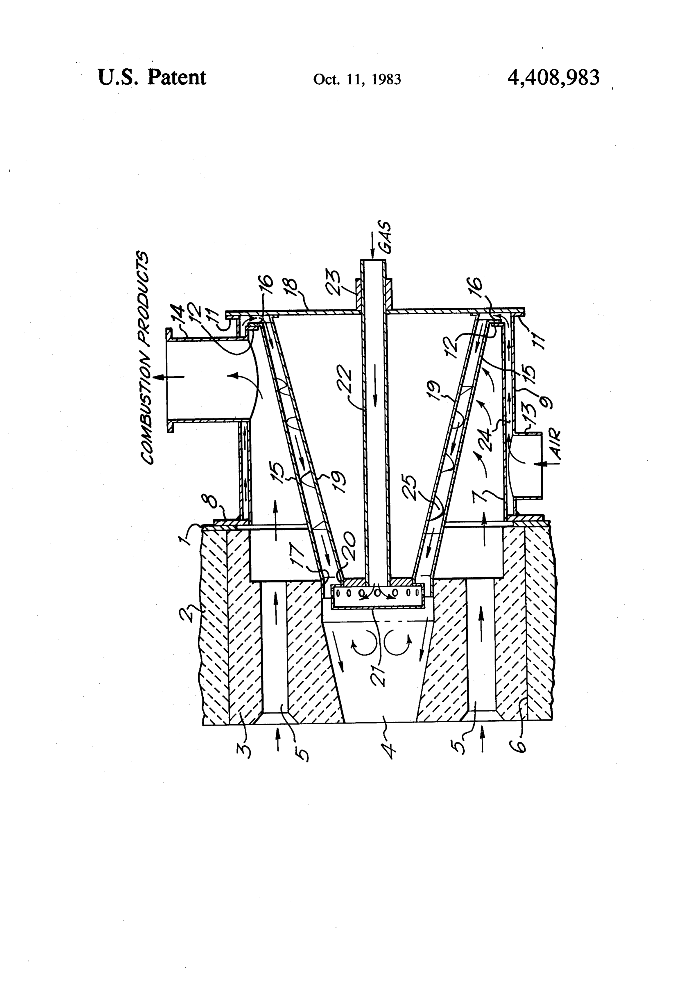
This invention relates to recuperative burners for use wall by its inner flange 8 to which is attached a cylindri in fuel-fired industrial furnaces, heat treatment furnaces 5 cal outer sleeve.9 having an outer flange 11. The recu and similar appliances of the kind wherein, in use, fuel perator chamber 7 has an outer flange 12. An inlet 13 for and combustion air are delivered separately by way of combustion passages to a mixing nozzle or respective fuel and air exit 14 for air is provided in the outer sleeve 9, and an combustion products passes through the nozzles directed into a combustion chamber where the outer sleeve to communicate with the recuperator fuel and air are ignited and which opens into a space for O chamber. The combustion products side of the recuper products of combustion, there being a combustion prod ator is completed ucts passage for conducting products of combustion 15 attached to the by an outer conical recuperator tube flange 12 of the recuperator chamber from the space to the exterior of the furnace, and the 7 by its flange 16 and supported within the combustion combustion air passage of the burner being disposed in chamber 4 at 17. A backplate 18 carries an inner conical use in heat-exchange relationship with the products 15 recuperator tube 19 and is attached to the flange 11 of passage to constitute a recuperator in which products of the outer sleeve combustion indirectly preheat the combustion air pass nozzle 21. Fuel gas9 isand to a rear part 20 of a burner supplied to the nozzle 21 through ing along the air passage. Such recuperative burners are a central tube 22 which is supported through a boss 23 hereinafter referred to as being "of the kind described'. in the backplate 18. Ancillary equipment. e.g., for igni Recuperative burners, for example, of the kind dis 20 and flame detection is incorporated but not shown. closed in British Pat. No. 1,331,427, have been exploited tionWhen the burner is in use, combustion products flow in recent years in a wide variety of applications. Their from the furnace through passageway 5 into the recu main advantage is the substantial reduction in fuel costs perator chamber 7 which they leave through exit 14. that results when heat that would otherwise be wasted Combustion air, driven by a fan (not shown), enters the is extracted from the combustion products and used to 25 burner at inlet 13 and passes through the passageway 24 preheat the incoming air. Compactness is another at between the wall of recuperator chamber 7 and sleeve 9 tractive feature of such burners. Experience has shown, to enter the conical annular space 25 between the outer however, that the elaborate tubular construction of the and inner conical recuperator, though effective, is expensive to manufac the combustion airrecuperatorprogresses tubes 15 and 19. Thus, as through the passageways ture and more troublesome than is desirable to maintain. 30 24, 25 into the combustion chamber 4, it is indirectly In some applications, distortion of the tubes occurs preheated by heat exchange with the outgoing combus during use so that dismantling is difficult and re-assem tion products.
bly impossible without extensive replacement of com ponents. When the burner is taken out of use for maintenance and
An object of the invention is to simplify the construc 35 nozzlehas to be dismantled, the whole assembly of tube 19, tion of recuperative burners in a way that reduced costs, detached21,from fuel tube 22, mounted on flange 18 is first facilitates maintenance and retains the advantages of cal construction,thewhich flange 11 and withdrawn. The coni ensures that tubes 15 and 19 thermal efficiency and compactness. cannot interlock, even though they may have distorted, Accordingly, the invention provides a recuperative makes this operation quite straightforward. The conical burner of the kind described in which part of the length recuperator tube 15 is then detached from the flange 12 of the combustion air passage in heat-exchange relation and withdrawn. It readily disengages from the quarl ship with the products of combustion may be formed as block 3 because there is no mechanical seal at 17 and a truncated substantially conical annular space which consequently no fastenings have to be freed which have converges towards the burner nozzle.
Preferably, the conical annular space is defined be 45 been In in service in the hottest part of the recuperator.
comparison with known recuperative burners in tween a detachable outer conical tube and an inner which the recuperator is constructed from concentric, conical tube which is detachably supported within the parallel-sided tubes, the present invention has several outer conical tube by support means. advantages. Ease of maintenance is one and it arises not The remaining part of the length of the combustion merely because the several components are separable air passage may be formed as a substantially cylindrical 50 but also because they can readily be disengaged. In annular space which is arranged to be in communication known recuperative burners, distorted tubes can lock with the conical annular space and with an air inlet. together so that it becomes necessary to cut through Conveniently, the cylindrical annular space can be de them before they can be withdrawn one from another. fined between outer and inner substantially cylindrical They cannot then be reassembled and must be replaced. tubes of a detachable assembly. 55 The conical construction of the main part of the recu Then the combustion products passage will be pro perator in accordance with the present invention elimi vided by an annular space between the outer conical nates the possibility of interlocking and in consequence tube and the inner cylindrical tube, and will communi the components, though they may have distorted, can cate with a flue outlet therefrom. more often be refurbished and re-used. Only severely One embodiment of the invention will now be described, by way of example, with reference to the further damaged components need be replaced. Disengagement single FIGURE of the accompanying drawing which is of the conical recuperator tube 15 from the quarl block 3 at 17, also, is straightforward because it is no longer a longitudinal sectional elevation. necessary to provide a mechanical seal at the end of the Referring to the drawing, the wall of a furnace in combustion air passageway 25 to prevent leakage of air which the burner is mounted is formed as an outer metal 65 into the combustion products passageway 4. Instead, skin 1 and an inner refractory lining 2. A refractory the low pressure region created around the nozzle 21 by quarl, block 3, having a central combustion chamber 4 the air flow into the combustion chamber 4 is made use and combustion products passageways 5, is supported of to ensure that leakage is always from the combustion 4 products passageway 5 into the air passageway 25. cating with said conical annular space and with an air Leakage in this direction is acceptable and can even be inlet.
desirable in some applications. Moreover, because the 2. A recuperative burner according to claim 1, inner structure of the recuperator now has to suppor wherein the conical annular space is defined between a less weight it is less likely to distort. detachable outer conical tube and an inner conical tube As well as ease of maintenance, the invention has the which is detachably supported within the outer conical advantage of improved design flexibility, resulting in tube by support means.
the main frame the introduction of conically fitting 3. A recuperative burner according to claim 2, components. The cone angle of the outer conical recu wherein the cylindrical annular space is defined be perator tube 15 may be varied to influence the propor 10 tween outer and inner substantially cylindrical tubes of tion of heat exchanged between the combustion prod a detachable assembly.
ucts and incoming combustion air that is transferred by 4. A recuperative burner according to claim 3, radiation. Furthermore, a different cone angle may be wherein the combustion products passage is formed as used for the inner conical recuperator tube 19 to pro an annular space defined between said outer conical gressively alter the cross-sectional area of the annular 15 tube and said inner cylindrical tube, and which commu nicates with a flue outlet.
space and influence the velocity of the air flow. The 5. A recuperative burner according to claim 2, greater scope that these variations afford enables the wherein the burner nozzle assembly and a fuel supply designer to optimise the amount of air preheat for a pipe specific application of the invention and to exercise support means.are detachably supported at least by a therefor some control over the distribution of heat transfer 20 6. A recuperative burner according to claim 5, in within the recuperator and hence over surface tempera cluding a burner quarl of refactory material having a tures. This will be of particular benefit in applications to central processes operating at temperatures, below 1200 C. tures forcombustion chamber and a plurality of exit aper where heat recovery will be significantly increased, ment beingthesuch passage of waste products, the arrange that, in use of the burner, the quarl is thus giving greater fuel savings. Manufacturing toler arranged to be detachably supported in an aperture in a ances could be reduced, in some applications, by incor furnace wall, and wherein an assembly of said outer and porating a helical guide, indicated at 26, into the com inner cylindrical tubes with an associated air inlet and bustion air passageway, which effectively increases the flue flow path for air through the recuperator and allows the inneroutlet and forming said cylindrical annular space, said outer conical tubes, and said support means passageway to be increased in size without losing air supporting said burner nozzle and fuel supply pipe, is preheat or producing excessively high surface tempera 30 attached to the exterior wall of the furnace and in align tures. ment with the quarl so that said annular combustion The absence of a mechanical seal at the combustion products passage communicates with said products chamber inlet is another feature that contributes to exit-apertures and said combustion air passage and said design flexibility. When necessary, this part of the burner nozzle communicates with said combustion burner may easily be modified so that, rather than mini 35 chamber.
mising leakage of combustion products into the com 7. A recuperative burner according to claim 6, bustion air, some degree of products recirculation is wherein the outer conical tube is detachably secured at allowed. Thus, by simple means, a reduction in flame its larger diameter end to an end of said inner cylindri temperature sufficient to give a substantial decrease in cal tube, and is supported at its smaller diameter end by the formation of nitrogen oxides may be achieved. 40 engagement with the quarl at the entrance of its com Finally, there are cost advantages. Manufacturing bustion chamber.
costs are considerably reduced by the simplified con 8. A recuperative burner according to claim 7 struction whilst running costs are reduced by the lower wherein, in operation thereof, a relatively low pressure fan power requirements resulting from smaller pressure region created around the nozzle by the flow of com losses in both the combustion air and combustion-prod 45 bustion air into the combustion chamber is made use of ucts passageways. Maintenance becomes less costly to ensure that any gas leakage between the smaller because procedures are simplified and component life is diameter end of the outer conical tube and its point of increased. engagement with the combustion chamber of the quarl We claim: is in the direction from the combustion products pas 1. In a recuperative burner of the kind wherein, in sage into the combustion air passage.
use, fuel and combustion air are delivered separately by wherein 9. A recuperative burner according to claim 5, way of passages to a burner nozzle assembly in the form plate said support means comprises an end closure of a mixing nozzle or respective fuel and air nozzles which is detachably secured to an end of said which opens into a space for products of combustion, outer cylindrical tube.
10. A recuperative burner according to claim 2, there being a combustion products passage for conduct 55 wherein ing products of combustion from the space to the exte varied fortheselectively cone angle of said outer conical tube can be influencing the proportion of heat rior of the furnace, and the combustion air passage of exchanged between the the burner being disposed in use in heat-exchange rela and incoming combustionoutgoing air. combustion products tionship with the products passage to constitute a recu 11. A recuperative burner according to claim 1, perator in which products of combustion indirectly preheat the combustion air passing along the air pas 60 wherein space is the cross-sectional area of said conical annular constant.
sage, the improvement wherein part of the length of the 12. A recuperative burner according to claim 1, combustion air passage in heat-exchange relationship with the products of combustion is formed as a trun wherein length of means are provided in at least part of the whole said combustion air passage to cause air flow cated substantially conical annular space which con ing therethrough to take a spiralling path. verges towards the burner nozzle assembly and wherein. 65 13. A recuperative burner according to claim 1, the remaining part of the length of the combustion air wherein the cross-sectional area of said annular space passage is formed as a substantially cylindrical annular varies along the length thereof.
space surrounding said conical annular space communi k k is k
Provenance
- Collection
- Patents citing this work
- Pages
- 4
- Method
- pdftotext (the PDF's own text layer) + pdftoppm 300dpi page scans
- Patent office record
- patents.google.com →
- Source
- Google Patents citing-documents table
- Assignee
- British Gas Corporation
- Published
- 1983-10-11
- Transcribed from
- patentimages.storage.googleapis.com →