

patent · US4416260A
Solar heating system for greenhouses and the like
22 November 1983
Text
Page 1bibliographic recordscan →
United States Patent (19)
Proctor
54). SOLAR HEATING SYSTEM FOR
GREENHOUSES AND THE LIKE
(75) Inventor: Budd L. Proctor, Manchester, Mo.
Assignee: PSI Energy Systems, Inc., Fenton,
51 Int. Cl. ... a - - - - - - - -- - - - - - - - - - - x F24J 3/02
U.S. C. .................................... /429,126/430,
3,902,474 9/1975 Pyle ..................................... 26/422 4,051,999 10/1977 Granger et al. . ... 26/400X 4,088,266 5/1978 Keyes.............. ... 264OOX 4,099,558 7/1978 Bricard et al. ... 126/400X 4,103,825 8/1978 Zornig ......... ... 126/400X 4, 1,185 9/1978 Swann .......... ... 26/400 X 4, 14,498 2/1979 Marschner ... ... 126/437 X 4,192,454 3/1980 Rugenstein . 126/437 X 4,196,719 4/1980 Skrivseth ... ... 126/430 4,201,192 5/1980 Coxon et al. ........................ 126'422 4,203,424 5/1980 Coxon et al. ........................ 126/422
4,213,447 7/1980 Erickson ............................. 126/429
4,244,519 1/1981 Zornig et al. ....................... 126/430
4,294,228 10/1981 Kruger et al. ...................... 126/430 4,307,701 12/198 Balon et al. .................... 98/40 CX Primary Examiner-Samuel Scott
Assistant Examiner-Randall L. Green
Attorney, Agent, or Firm-Glenn K. Robbins
A solar heating collector is employed in the form of a plenum constituted of the greenhouse translucent roof and a roof floor of black plastic sheeting. Hot air from the plenum is distributed by air directing means to a heat storage chamber in a charge cycle or directly to the greenhouse in a direct heat cycle. In a discharge cycle air from the greenhouse is directed through the heat storage chamber to be heated and discharged into the greenhouse. Specially designed collapsible tubes are employed in the system for distribution of exhaust air and distribution of heated air from a manifold. The heat storage chamber employs cylindrical containers of a phase change material to store solar energy and serves to support the air directing means and the aforemen tioned collapsible tubes to provide a central unit for providing and monitoring solar heat distribution.
7 Claims, 12 Drawing Figures
Drawings
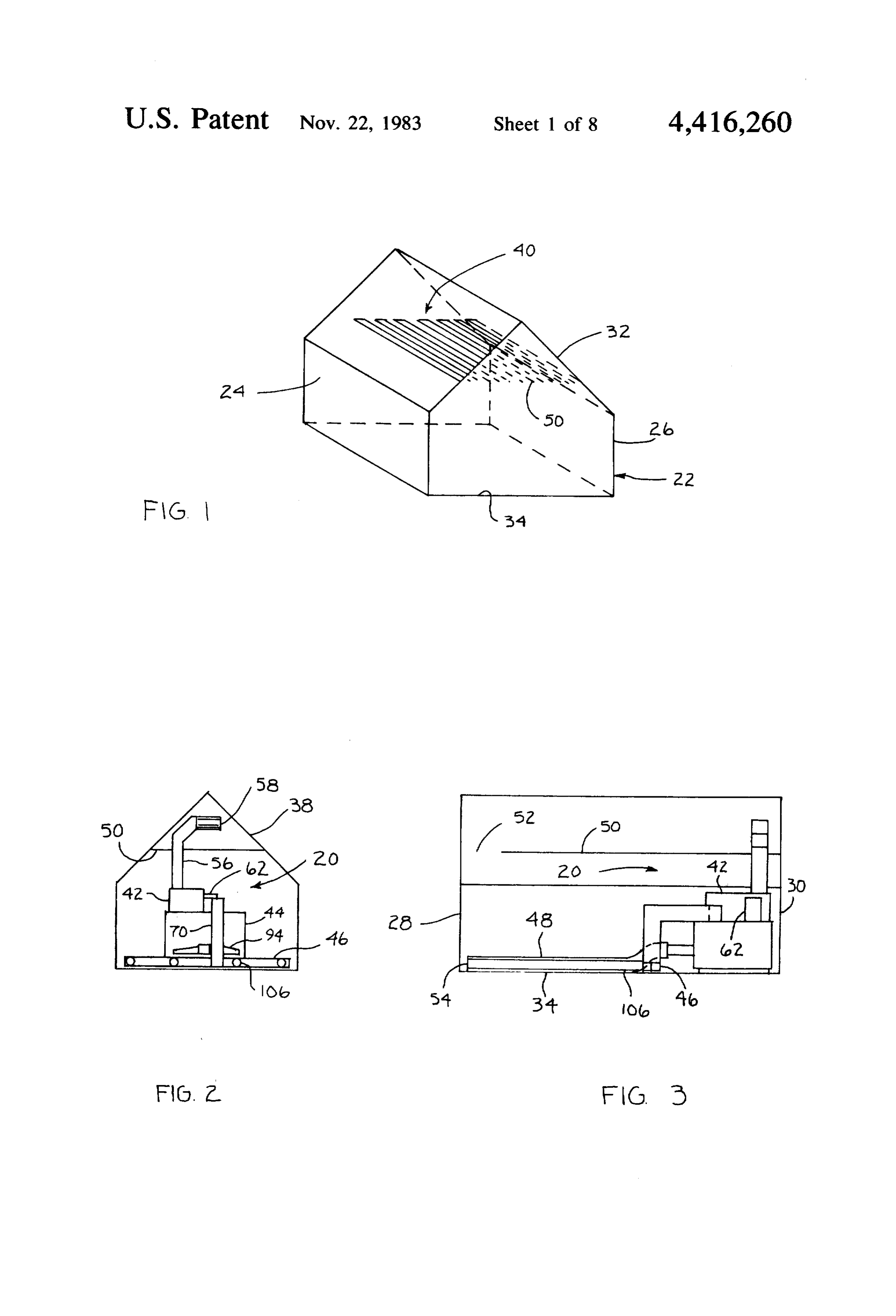
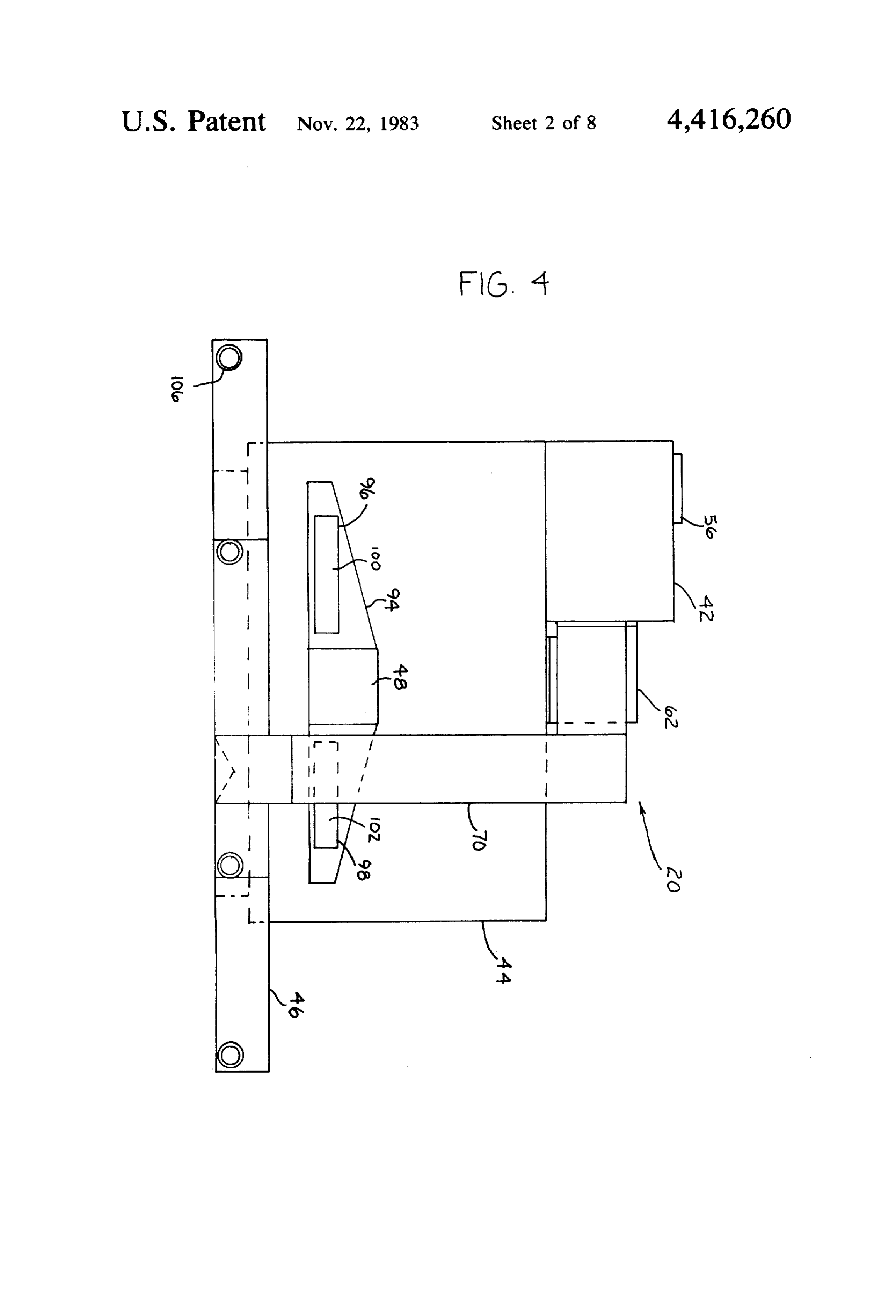
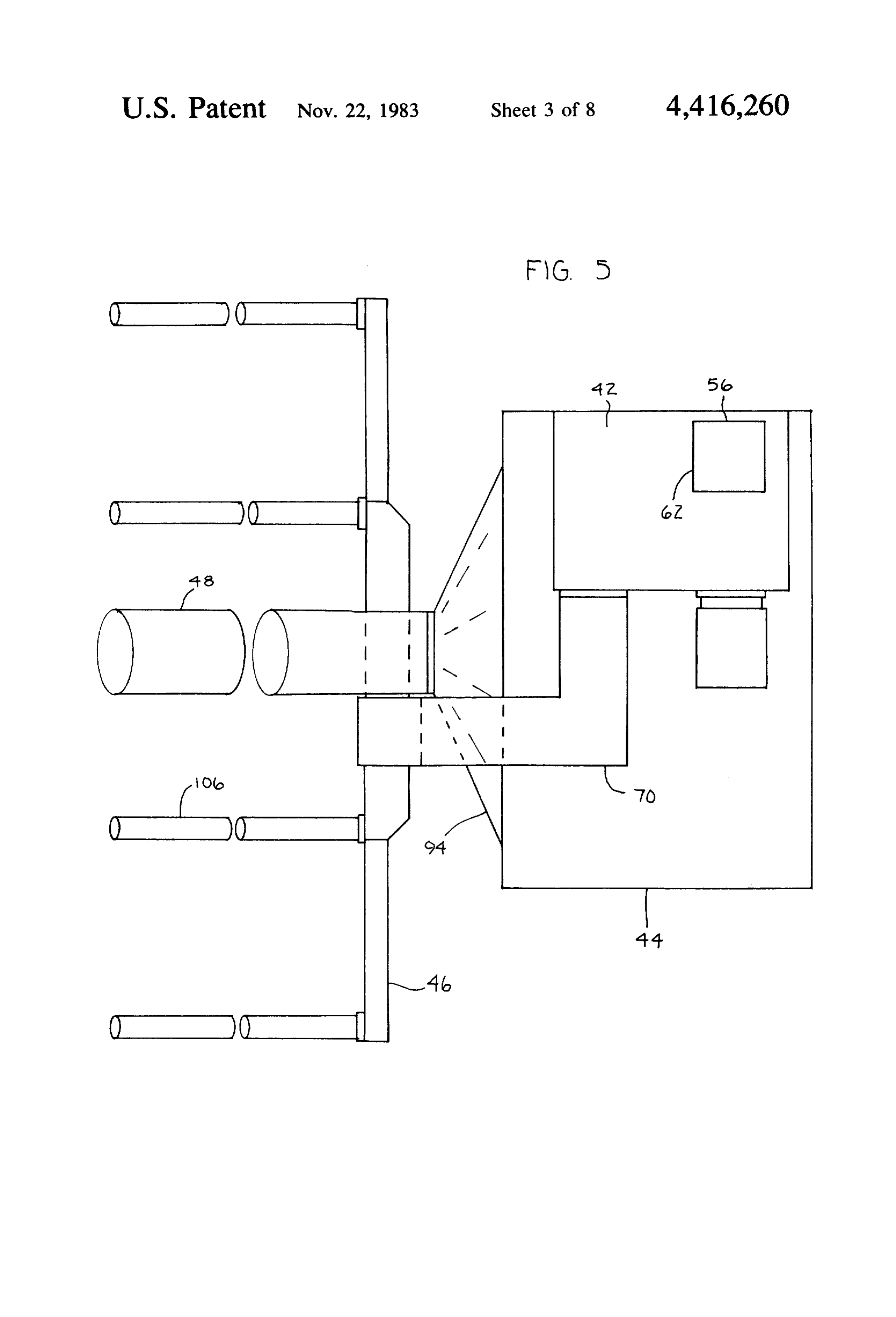
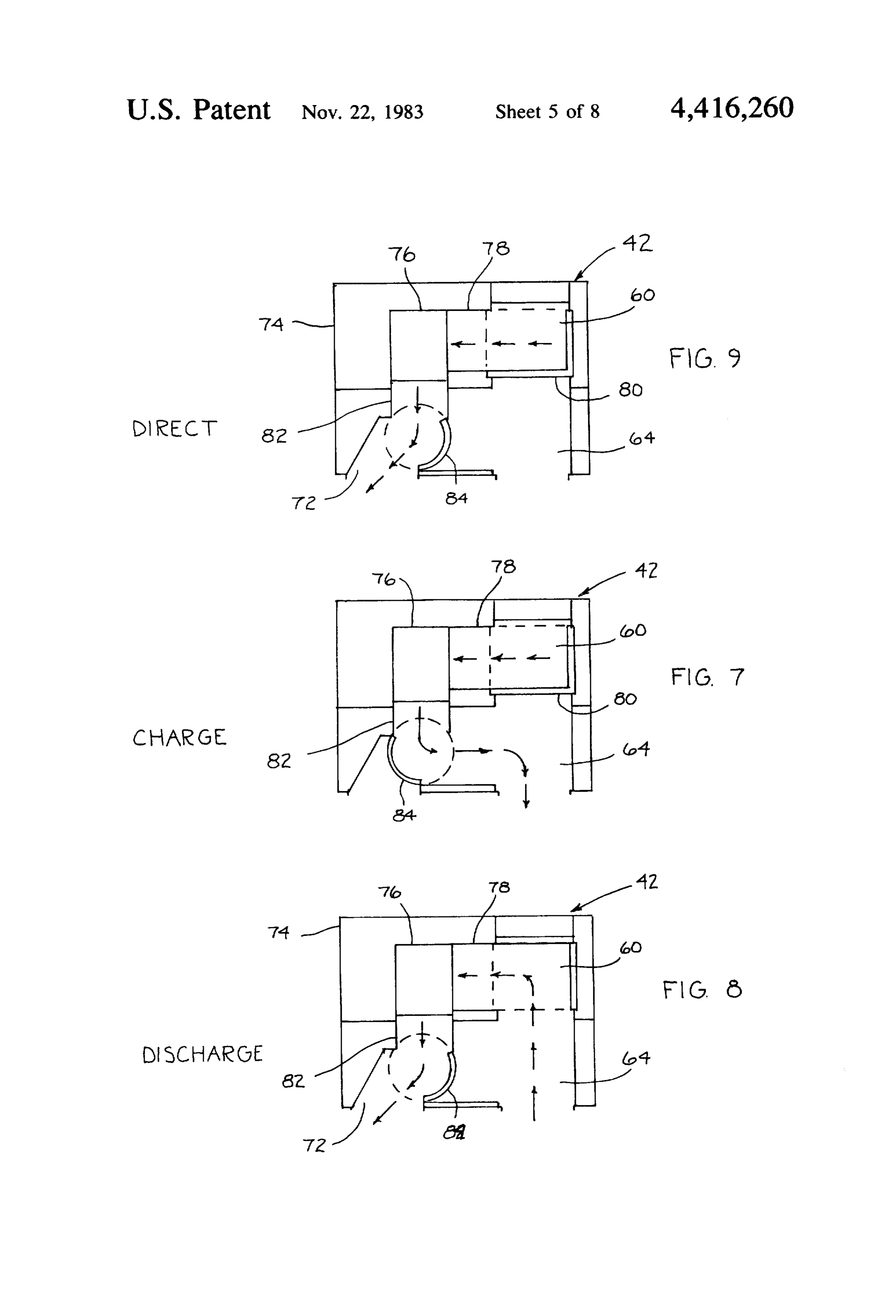
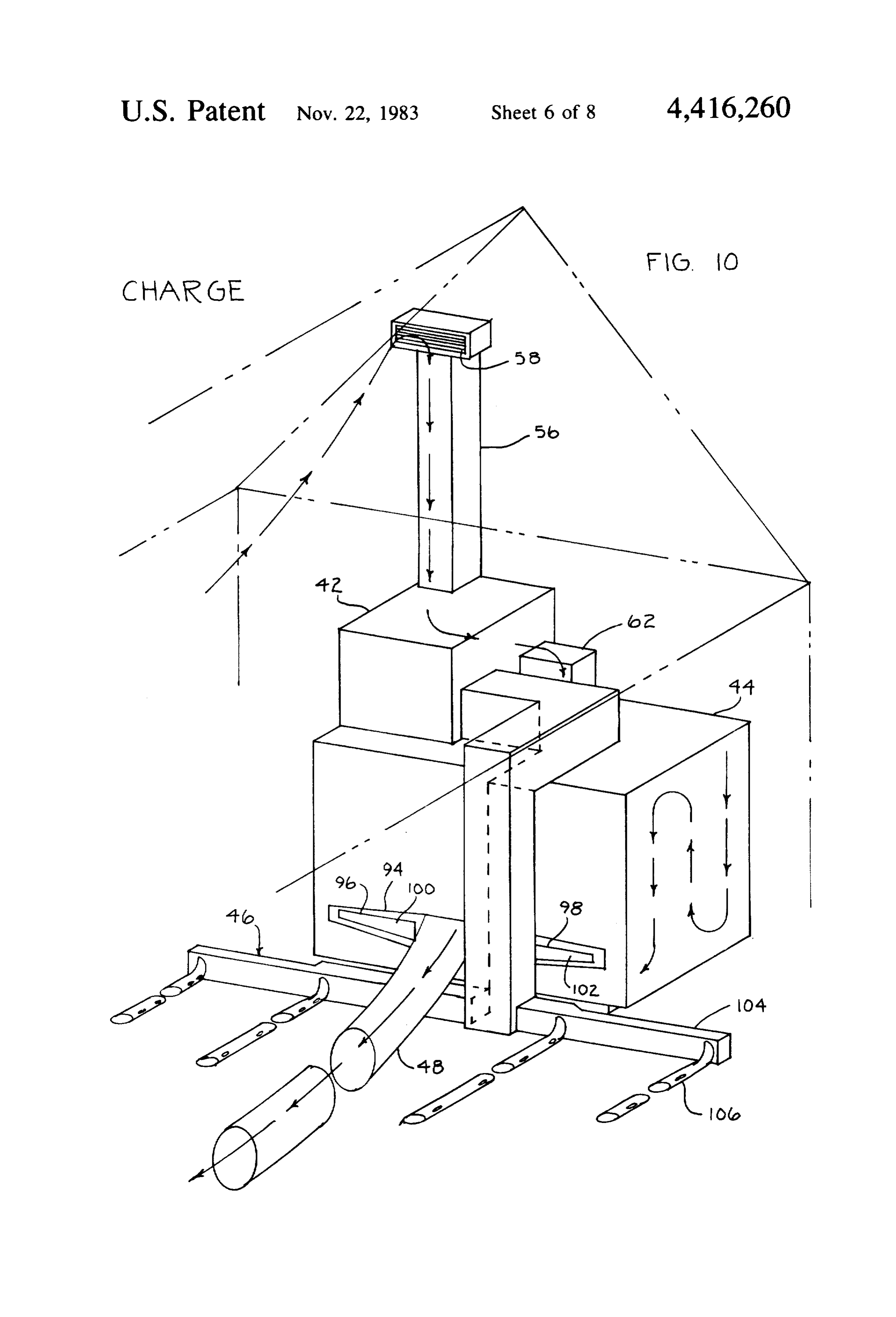
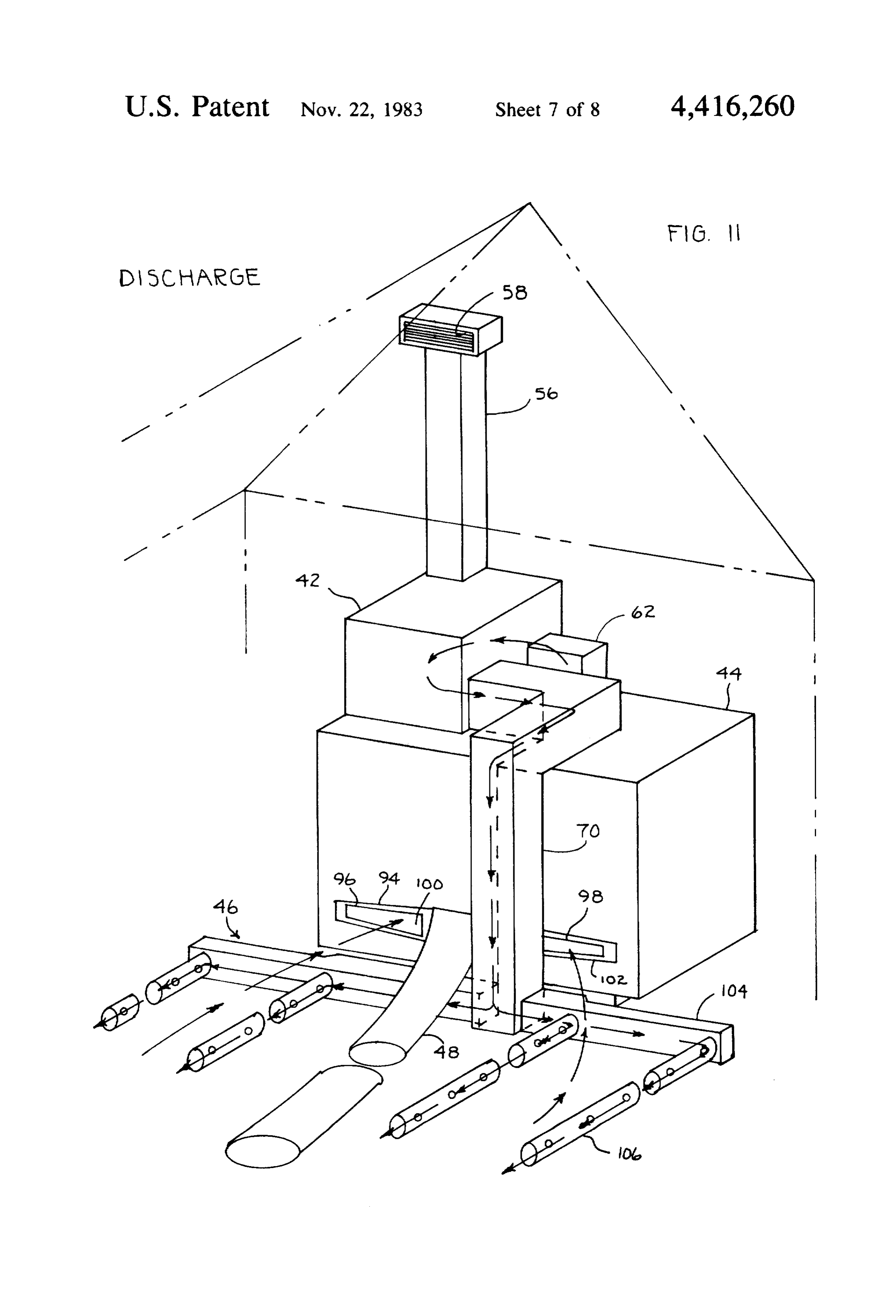
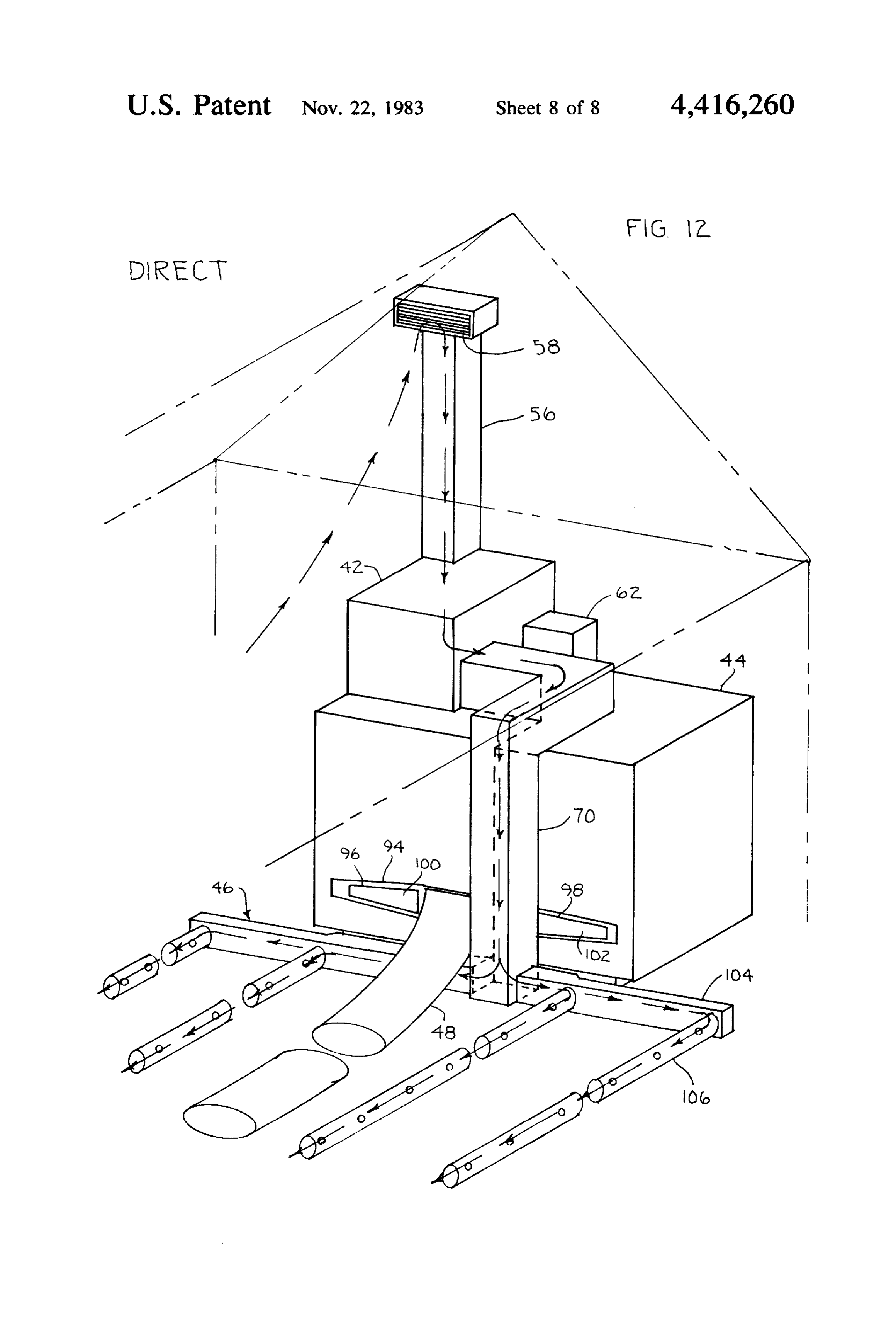
FIG. 11 is a view similar to FIG. 10 showing distribu mentioned tion of heated air from the heat storage unit to the 7 and 10. Inairorder 40 distribution are best shown in FIGS. 2-4, to provide for passing air from the greenhouse in a discharge cycle; and
FIG. 12 is a view similar to FIG. 10 showing distribu solar collector plenum to the air directing means an tion of solar heated air to the greenhouse in a direct upstanding duct 56 extends from the top of the air di recting means into the solar collecting plenum. An heating cycle.
Page 2drawing sheetscan →
Page 3drawing sheetscan →
Page 4drawing sheetscan →
Page 5scan →
sc)-O CCCCCs
Y Yes N s
8X2 S. O 6a 90 S.
Ns n n s
SC 8:8 S
S. O N :a -92 S5
So n s
7777.7777.77 AACAAAAACAaaaaaaaaaaaaaaaaaaaaay
Page 6drawing sheetscan →
Page 7drawing sheetscan →
Page 8drawing sheetscan →
Page 9drawing sheetscan →
Page 10scan →
of the black plastic sheet which may be any conven
SOLAR HEATING SYSTEM FOR GREENHOUSES tional plastic sheet material such as polyethylene or the AND THE LIKE like. The solar collector plenum further serves as a source of insulation during periods of heat requirement
BACKGROUND OF THE INVENTION 5 such as night fall or the like. The black plastic sheet In the past various types of solar heating systems serves as a heat protective ceiling for the greenhouse to have been devised for heating building structures. Gen minimize heat escape from the interior of the green erally these systems have employed a solar collector of house.
one type or another employed with duct work and The heat storage chamber and air directing means are blowers for distributing heat directly from the solar 10 constructed as a central physically connected central collector to the building or a heat storage unit such as unit to provide for ease in monitoring the various heat rock or thermal energy storage units which contain a cycles and servicing of the heat distribution system. By phase change material for high heat storage capacity. appropriate duckwork the air directing means is con Heat from the heat storage unit may be recaptured by nected to the heat storage chamber and the heat distri directing air thereover and recycling to the building 5 bution manifold. The air directing means is constituted when needed. of a valve system for directing the air by a blower in the It has been a particular problem to heat greenhouses charge cycle where hot air from the solar collector and similar spacious buildings because of the high heat plenum is directed to the heat storage chamber to pro loss in cold weather. Such greenhouses, while absorb vide heat thereto. A discharge cycle is employed by the ing a substantial amount of heat in cold sunny days air directing meeans in which air from the greenhouse is through passive solar absorbtion rapidly lose their heat drawn through the heat storage chamber and is then at night fall. This rapid heat loss is due to the nature of directed through a hot air manifold for distribution to construction of roof and walls of glass or translucent the greenhouse. A direct heat cycle is furnished in plastic and also because of the spaciousness of the inte which the air directing means draws air from the solar collector plenum and distributes it directly to the hot air
It will further be understood that in such greenhouses manifold.
certain areas containing different types of plants may The hot air manifold is comprised of a laterally ex require warmer temperatures than other areas which tending header conduit which is connected to a plural may contain hardier plants or otherwise may not re ity of flexible collapsible plastic conduits which may be quire as warm a temperature. 30
While various solar heating systems have been pro of polyethylene or other conventional plastic. These posed, it has continued to be a problem to devise effi conduits are provided with perforations or openings along their length to provide for distribution of heat as cient and practical solar heating systems for green desired. The conduits may be positioned as desired in houses and similar buildings of spacious interior.
35 appropriate locations on the floor of the greenhouse to
SUMMARY OF THE INVENTION provide heat to selected areas,
By means of the instant invention there has been In order to provide for efficient utilization of exhaust divised a solar heating system for greenhouses and the air from the heat storage chamber in the charge cycle a like which takes advantage of the translucent nature of collapsible flexible exhaust tube is connected to an the roof to provide a solar collector using a black plastic 40 opening in the storage chamber. The exhaust tube may sheet as a plenum boundary or floor. A self contained be positioned on the floor of the greenhouse and termi air directing means and heat storage chamber is em nate underneath an opening in the black plastic sheet at ployed within the greenhouse with flexible and collaps an area of the greenhouse remote from the heat storage ible conduits for heat exhaust and heat distribution from chamber. In this way exhaust heat may be recycled to a hot air manifold. Through the use of flexible heat 45 the solar collector plenum for full efficiency. distribution conduits the heated air can be distributed as The exhaust tube is collapsible in order that it close in desired to those areas of the greenhouse that require the discharge cycle where air is drawn through com heat, panion ports communicating with the exhaust outlet in The solar collector plenum essentially employs the the heat storage chamber. The companion ports in the peaked roof of the greenhouse having translucent roof 50 charge cycle are closed by a damper which is opened by walls to provide a plenum space to be heated by radia negative air pressure and closed by positive pressure. tion. The black plastic sheet stretches from one side of The heat storage chamber serves as a base or founda the roof to the other or from a point low on a south wall tion for the solar heat collecting system with the solar to the peak providing an inclined plenum and serves to collecting plenum and serves as a central area for ser absorb heat from the sun. The heat from the solar col 55 vicing and monitoring the system. It is constructed of an lector plenum is employed to store heat in a heat storage insulated box-like housing with interiorly staggered chamber in a charge cycle when the greenhouse does baffles to provide a tortuous path between an outlet at not need heat or can be employed in the greenhouse in one side communicating with the air directing means a direct heat cycle. When heat is needed from the heat and another oulet at a far side of the housing communi storage chamber, air is directed from the greenhouse cating with the aforementioned exhaust conduit and through the heat storage chamber to be heated and is companion ports. The passageway is filled with poly then returned to the greenhouse. It will also be under ethylene containers of a phase change material such as stood that this heat disctribution may be in a separate calcium chloride hexahydrate to provide an efficient building as desired by simply extending the duct work high heat capacity thermal energy storage chamber. and hot air manifold thereto, 65 The aforedescribed solar heating system may be sin The solar collector plenum thus serves as a simply ply installed in greenhouses or the like in a simple effi contructed chamber utilizing existing translucent roof cient and low cost manner without the requirement of walls of the greenhouse and requires only the addition complex reconstruction and ductwork. While a green 11 house building has been particularly described it will be plastic sheet 50 of polyethylene or similar plastic sheet understood that other like structures of a spacious inte ing material. The black plastic sheet forms a floor of the rior may be similarly utilized. solar collector and acts to absorb radiant energy from The above features are object of this invention. Fur the sun admitted through the translucent roof and forms ther objects will appear in the detailed description 5 an efficient, simple and inexpensive means for collecting which follows and will be otherwise apparent to those the substantial amount of heat available in the unused skilled in the art. top portion of the greenhouse. The black plastic sheet as For the purpose of illustration of this invention, a will be well understood, may be simply supported preferred embodiment is shown in the accompanying where necessary by transverse wire supports extending drawing. It is to be understood that this is for the pur O from one side of the roof to the other. The plenum floor pose of example only and that the invention is not lim formed by the black plastic sheet is spaced as shown in ited thereto. FIG. 3 a short distance from the end wall of the green IN THE DRAWING house to provide an exhaust opening 52 for air directed from the solar collector plenum by the air directing
FIG. 1 is a pictorial view of a greenhouse provided 15 means 42 through the heat storage chamber and out the with the black sheet plenum floor; exhaust tube 48 at an open end 54. The plenum opening FIG. 2 is a view in front elevation of the greenhouse is positioned substantially vertically above the end of provided with the solar heating system of this inven the exhaust tube to provide for efficient utilization of tion; unrecovered exhaust air and to prevent any unwanted FIG. 3 is a side view of the greenhouse taken from heating of the greenhouse.
the left side of FIG. 2; The air directing means is essentially a three way air FIG. 4 is a view in front elevation of the solar heating control unit with a blower for directing air in a charge distribution and storage unit; cycle from the solar collector plenum 40 to the heat FIG. 5 is a top plane view of the solar heating unit; storage chamber 44 when heat is desired to be stored as F.G. 6 is a view in vertical section of the heat storage in a sunny daytime period when passive heat collection unit; due to the translucent nature of the greenhouse walls is FIG. 7 is a schematic view of a flow control unit for distribution of solar heated air to the heating storage atas ainmaximum.
In a discharge cycle when heat is desired nighttime the air directing means pulls cold air unit in a charge cycle; from the greenhouse through the heat storage chamber FIG. 8 is a view of the flow control unit for distribu 30 and directs it out tion of heated air from the heat storage unit to the house. In a direct heat cycle the hot air manifold to heat the green greenhouse in a discharge cycle; when heat may be needed FIG. 9 is a view of the flow control unit for distribu in the greenhouse the air directing means draws avail tion of solar heated air to the greenhouse in a direct able hot air from the solar collector plenum and directs heating cycle; 35 it to the hot air manifold 46 for distribution to needed FIG. 10 is a pictorial view of the solar heating distri areas of the greenhouse as will be more fully described hereinbelow and thereby bypasses the heat storage bution and storage unit for distribution of solar heated chamber.
air to the heat storage unit in the charge cycle;
The duct work connections to accomplish the afore
FIG. 11 is a view similar to FIG. 10 showing distribu mentioned tion of heated air from the heat storage unit to the 7 and 10. Inairorder 40 distribution are best shown in FIGS. 2-4, to provide for passing air from the greenhouse in a discharge cycle; and
FIG. 12 is a view similar to FIG. 10 showing distribu solar collector plenum to the air directing means an tion of solar heated air to the greenhouse in a direct upstanding duct 56 extends from the top of the air di recting means into the solar collecting plenum. An heating cycle.
opening 58 in this duct receives hot air and discharges
DESCRIPTION OF THE INVENTION into opening 60 in the air directing means. This duct The solar heating system of the invention is generally provides for passage of air from the solar collector indicated by the reference numeral 20. It is shown in plenum through the air directing means in both the stalled in a greenhouse 22 in FIGS. 2 and 3 and partially charge and direct heat cycles.
installed in FIG. 1. 50 A duct 62 as shown in FIGS. 2, 3, 4, 5 and 10 provides The greenhouse 22 is of conventional structure hav for communication between the air directing means and ing the usual side walls 24 and 26, end walls 28 and 30 the heat storage chamber through an opening 64 in the and roof 32 supported upon a floor 34. The roof 32 is air directing means and a top opening 66 in the heat peaked and is comprised of converging roof walls 36 storage chamber. This duct provides for passage of air and 38 forming a conventional triangular roof. The roof 55 from the air directing means to the heat storage cham walls may be constructed of glass or translucent plastic ber in the charge and discharge cycles. as will be well understood in the art. A duct 70 as shown in FIGS. 2-5 and 10 serves to The solar heating system is comprised of a solar col communicate the air directing means with the hot air lector plenum 40 formed in the roof and appropriate distribution manifold in the direct heat cycle. This is duct work connecting it with an air directing means 42 accomplished by duct openings 70 in the air directing and a thermal energy or heat storage chamber 44 for means at the top of the duct while the lower end is storage of solar heat from the solar collector plenum. connected to the hot air manifold. For distribution of hot air and exhaust air a hot air The air directing means is simply a means for direct manifold 46 is connected to the air directing means ing air through it to provide for change in air direction while an exhaust tube 48 is connected to the heat stor 65 through the various charges, discharges and direct heat age chamber. cycles. As an example, the air directing means may be The solar collector plenum is formed of the top por that as shown in U.S. Pat. No. 4,262,655. The air direct tion of the roof walls 36 and 38 connected by black ing means is shown in the various cycles in FIGS. 7, 8 12 and 9 for the charge, discharge and direct heat cycles, OPERATION respectively.
The air directing means as shown in these Figures is The solar heating system of this invention is very comprised of a housing 74 having a blower fan 76 for simply employed. The air directing means and the heat forcing air in a controlled direction. The fan has an inlet storage chamber and the duct work necessary for heat opening 78 communicating with a semi-cylindrical distribution and collection can be furnished as a unitary valve 80 for opening and closing access to opening 60 package system. The heat conduits from the hot air leading to the solar collector plenum and opening 64 the manifold and the exhaust tube are simply positioned in leading to the heat storage chamber opening 66. The 10 sired.greenhouse in any placement configuration as de semi-cylindrical valve operates on a horizontal axis to open and close the aforementioned openings from ac tionTheof only the construction required to fit the configura greenhouse is the emplacement of the black cess to the inlet 78 of the fan.
An outlet opening 82 of the fan communicates with a side plastic plenum floor sheet 50 which stretches from one second semi-cylindrical valve 84. This valve operates 5 supported of the roof to the other. The plastic sheet is simply on a horizontal axis and opens and closes access to the and may bebysupported appropriate affixation to the roof walls where desired upon stringers of opening 72 leading to the hot air manifold and the afore wire or the like. After such support the plenum duct 56 mentioned opening 64 leading to the heat storage cham is fitted through a cut-out opening in the plenum floor ber. and the exhaust opening is cut at an end of the green The heat storage chamber is best shown in detail in 20 house remote from the central unit comprised FIG. 6. As there shown it is comprised of a box-like directing means and the heat storage chamberofand the air the housing 86 having insulated walls 88. It is provided with connecting duct work and the hot air distribution mani the aforementioned opening communicating with the fold.
air directing means and a bottom opening 90 leading to In operation the solar heating system can be simply the exhaust tube 48 and a damper controlled inlet port 25 and efficiently changed between the various charge, as will be more fully described hereinbelow. Staggered discharge and direct heat cycles. This change may be baffles 88 and 90 connected at the top and bottom of the manually effected or by appropriate instrumentation interior of the housing provide a tortuous passage 92 that may sense the heat load requirements depending on within which are stored cylindrical containers 93 of a the various temperatures in the ambient air outside the thermal energy storage material. These containers de 30 greenhouse, the weather and sun conditions, the tem sirably may be of polyethylene tubes filled with a phase perature within the solar collector plenum and heat change material of calcium chloride hexahydrate as an storage chamber and at various points within the green example. This phase change material because of its house.
melting point of about 81 F. to 27 C. provides a phase When the charge cycle is desired to be employed the change latent heat storage capacity considerably 35 air directing means is operated as shown in FIG. 7 to greater than the sensible heat provided by rock or the provide the direction of flow as shown by the arrows like. therein and in FIG. 10. In this cycle hot air from the The bottom opening of the housing is covered by a plenum is drawn through duct 56 through opening 60 plenum chamber 94 to which is connected the exhaust past valve 80 in the air directing means by the fan 76 and tube 48. This exhaust tube is constructed of flexible is forced past valve 84 through opening 62 into the heat polyethylene which will distend or expand in the storage chamber 44. The phase change containers 93 are charge cycle when exhaust air is forced through the heated and air is exhausted through the flexible exhaust heat storage chamber and exhausted. In the discharge tube 48 out the end and back to the plenum chamber cycle the flexible exhaust tube will collapse and close. through the exhaust opening 52. Provision for admission of room air to be heated in 45 In the discharge cycle negative pressure or suction the discharge cycle is made by inlet ports 96 and 98 in from the air directing fan causes the dampers 100 and the plenum chamber 94. These ports are closed by sim 102 to open and air from the greenhouse floor area to be ple sheet-like dampers 100 and 102 which open in the admitted through ports 96 and 98 and the opening 90 in discharge cycle by suction or negative pressure created the heat storage chamber to be drawn therethrough to by the fan 76 in the air directing means and are closed 50 be heated. The heated air from the heat storage cham by gravity or positive pressure in the other cycles. ber is then drawn through the top opening 66 into the The hot air manifold 46 is best shown in FGS. 2-5 duct 62 and the opening 64 in the air directing means 42 and 10. It is constructed of a transversely extending past valve 80 by the blower fan and is then forced past manifold chamber 104 closed at the end and connected valve 84 through duct 70 to the hot air manifold. The to a plurality of heat distribution pipe-like conduits 106. 55 hot air in the manifold is then discharged through the The conduits are desirably of polyethylene or similar hot air distribution conduits to desired areas in the plastic material and are flexible in order that they may greenhouse for heating.
be flexed and positioned in desired areas on the green In the direct heat cycle hot air from the solar collec house floor. The heat conduits 106 are closed at the tor plenum is drawn by the blower fan through duct 56 ends and are provided with perforations (not shown) in into the opening 60 of the air directing means past valve order that heat may be distributed along their length. 80 into the fan inlet as shown in FIGS. 7 and 12. The fan Through the flexible nature the conduits provide for forces under positive pressure the hot air past valve 84 distribution of heat and concentration in selected areas through opening 72 into duct 70 and the hot air mani of the greenhouse where plants may be located that fold for distribution to the selected areas of the green require more heat than in other areas. The flexible con 65 house through the flexible heating conduits 106. Hot air duits may also be made collapsible when air is not rising in the greenhouse is recycled back to the solar forced therethrough in the discharge and direct heat collector plenum through the plenum opening 52 to cycles as desired. complete the cycle.
Page 13scan →
While this invention has been described in particular exhausting air directed therethrough to an interior area reference to a greenhouse, it will be understood that of the greenhouse positioned substantially vertically similar buildings with translucent walls or portions underneath an opening in said black plastic sheet to thereof may be similarly equipped. Likewise the solar heat distribution system employing the air directing 5 provide for recycling of air to said roof plenum. means, the solar heat storage chamber and the flexible means forsolar 3. The heating system of claim 2 in which said exhausting air from the solar heat storage exhaust and hot air manifold with flexible heat distribu chamber comprises a flexible collapsible plastic exhaust tion conduits or tubes may be employed with various conduit means provided in communication with said types of solar collectors. heat storage chamber, said exhaust conduit being dis Various other changes and modifications may be 10 made within this invention as will be readily apparent to tendible by a positive air pressure to provide for passage those skilled in the art. Such changes and modifications of exhaust inairthetherethrough in the charge cycle and are within the scope and teaching of this invention as collapsible discharge and direct heat cycles, said conduit being collapsible by a negative pressure and its defined by the claims appended hereto. own weight in the discharge cycle and by its own weight 1. A solar heating system for greenhouses and the like having an in the direct heat cycle, said conduit means having a translucent roof, said system comprising a underneath opening positioned substantially vertically black plastic sheet spaced below an upper portion of the opening in said black plastic sheet. said translucent roof and extending transversely under heat 4. The solar heating system of claim 1 in which said the roof in spaced relation thereto to define with the 20 flexible distribution conduits are comprised of perforate roof a substantially enclosed plenum to provide a solar collapsible plastic tubes, said tubes being dis tendible in said discharge and direct heating cycles and collection space for hot air generated therein by solar collapsible energy, said black plastic sheet forming a floor of the in the charge cycle. roof plenum and a ceiling for a greenhouse space to be 5. The solar heating system of claim 1 in which a heated below, a solar integral self-contained heat stor 25 flexible collapsible plastic exhaust conduit means is age chamber supported upon a floor of the greenhouse, provided in communication with said heat storage air directing means supported within a housing con chamber, said exhaust conduit being distendible by a nected to and supported upon said chamber for selec positive air pressure to provide for passage of exhaust tively directing: air therethrough in the charge cycle and collapsible in (a) hot air from said roof plenum to said solar heat 30 the discharge and direct heat cycle, said conduit being storage chamber in a charge cycle, collapsible by a negative pressure and its own weight in (b) hot air from said roof plenum to a greenhouse the discharge cycle and by its own weight in the direct space to be heated in a direct heat cycle and, heat cycle.
(c) hot air from said solar heat storage chamber to a 6. The solar heating system of claim 1 in which said greenhouse space to be heated in a discharge cycle, 35 solar heat storage chamber is comprised of staggered the solar heat storage chamber being provided with vertically extending baffle members spaced from one means for directing hot air therefrom to a hot air another and provided with alternate openings on a top manifold to direct hot air to selected floor areas of and bottom of said chamber to provide a tortuous pas the greenhouse to provide heat thereto, said mani sageway between said first and second opening, said fold being comprised of a laterally extending con passageway being substantially filled with elongate duit supported above the floor of the greenhouse horizontally extending cylindrical containers of a phase and communicating with a plurality of longitudi change material to provide a thermal energy storage nally extending flexible heat distribution conduits chamber.
extending along and supported by the floor of the 7. The solar heating system of claim 1 in which said greenhouse, said flexible conduits being moveable 45 roof is comprised of converging translucent roof walls to said selected areas to provide variable heat and said black plastic sheet extends between said walls thereto as desired. to form the floor of said roof plenum and the ceiling for 2. The solar heating system of claim 1 in which the the greenhouse space to be heated below.
solar heat storage chamber is provided with means for k k k k
Provenance
- Collection
- Patents citing this work
- Pages
- 13
- Method
- pdftotext (the PDF's own text layer) + pdftoppm 300dpi page scans
- Patent office record
- patents.google.com →
- Source
- Google Patents citing-documents table
- Assignee
- Psi Energy Systems, Inc.
- Published
- 1983-11-22
- Transcribed from
- patentimages.storage.googleapis.com →