

patent · US4038967A
Solar heating system and components thereof
2 August 1977
Text
Page 1bibliographic recordscan →
United States Patent (19)
Stout et al.
(54) SOLAR HEATING SYSTEMAND
COMPONENTS THEREOF
(76 Inventors: Harry E. Stout; Brian Stout, both of 2 Brastow Ave., Somerville, Mass.
* Notice: The portion of the term of this patent subsequent to Nov. 11, 1992, has been disclaimed.
Related U.S. Application Data 63 Continuation-in-part of Ser. No. 489,150, July 17, 1974,
(51) Int. Cl?................................................ F24, 3/02 U.S. C. .................................................... 126/271
1,951,403 3/1934 Goddard .............................. 126/271 2,460,482 2/1949 Abbot ..... . 126/27 3,107,052 10/1963 Garrison ..... 126/27 3,939,819 2/1976 Minardi ................................ 126/271 Primary Examiner-Kenneth W. Sprague
Assistant Examiner-James C. Yeung
Attorney, Agent, or Firm-Morse, Altman, Oates & Bello
A lightweight, low cost, solar heat collecting system is provided for use with homes and other buildings. Solar heat collecting panels are mounted on a roof or other support and connected to the building's heating system, Aliquid black body medium is pumped to the elevated upper end of each unit and is allowed to drain down through each panel by gravity feedback into a storage tank where the heated liquid is circulated, on demand, through the building. Each heating panel is comprised of a rigid foam plastic frame having a back wall over which is disposed a reflective stratum. A sheet of plastic material having a black surface is bonded to the reflec tive stratum along spaced parallel lines to define a plu rality of parallel channels extending lengthwise of the panel. Manifolds are provided at opposite ends of the panel to feed the liquid into and drain the liquid from the channels. Spaced layers of flexible, transparent plas tic film are mounted to the frame across the front of the panel to pass radiant heat from the front to heat liquid in the channels and trap the heat absorbed by the panel. 2 Claims, 4 Drawing Figures
far
Drawings
Page 2drawing sheetscan →
Page 3scan →
posite ends of channels by which liquid is delivered at
SOLAR HEATING SYSTEM AND COMPONENTS one end and drained by gravity from the other end. THEREOF A pumping system is provided for circulating the liquid black body medium and a storage tank is con
CROSS-REFERENCE TO RELATED nected to the pumping system to store liquid heated
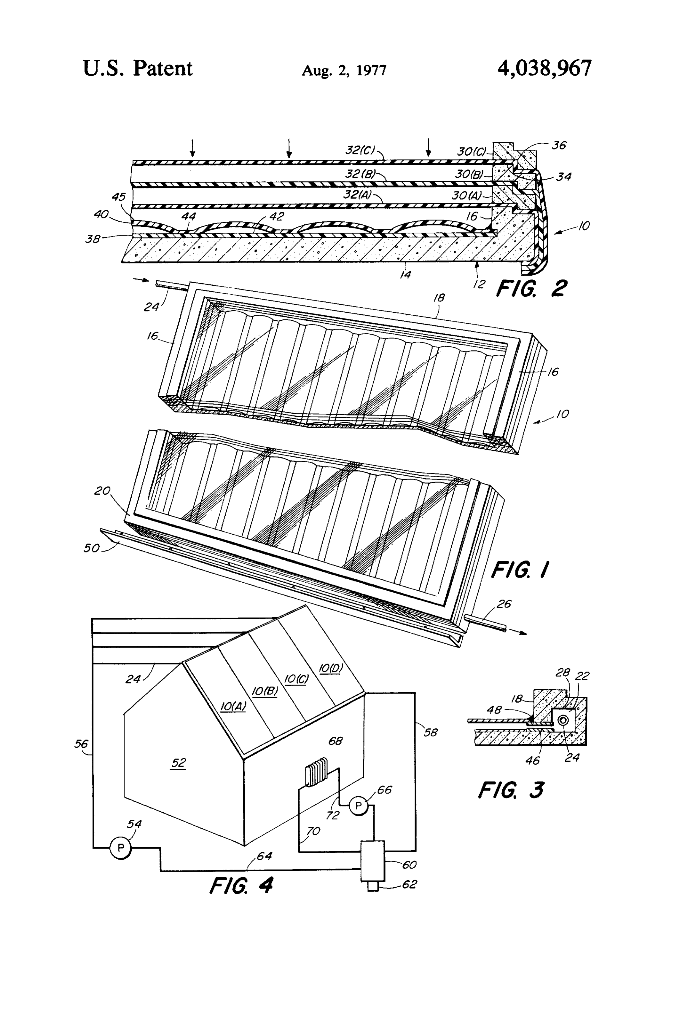
This is a continuation-in-part of U.S. application Ser. BRIEF DESCRIPTION OF THE DRAWINGS entitled "Solar Heating System And Components FIG. 1 is a view in perspective of a solar heating panel Thereof'. O made according to the invention, FIG. 2 is a fragmentary sectional view showing de
BACKGROUND OF THE INVENTION tails of the panel construction, 1. Field of the Invention FIG. 3 is a view somewhat similar to FIG. 2 showing This invention relates generally to solar heating sys further details of the panels, and, tems and more particularly is directed towards a new 15 ofFIG. 4 is a view in perspective, somewhat schematic, a typical heating system employing panels of the and improved, solar heating system employing simple, low cost, lightweight heat collecting panels mountable present invention.
to the roof of a building or the like and employing a DETAILED DESCRIPTION OF THE liquid black body medium to store and distribute ab 20 PREFERRED EMBODMENT sorbed heat.
2. Description of the Prior Art Referring now to the drawings, the reference charac ter 10 generally indicates a solar heating panel made
With the increasing cost of heating fuels as well as the according to the invention and generally organized increase experienced in the cost of generating electric about a rectangular frame 12 of a light weight, ther ity, a greater interest has developed in providing alter 25 mally insulating, inexpensive nate sources of energy, particularly for heating homes frame 12 is molded from styrofoam material. Preferably the and other buildings. Solar heating systems are of partic plastic material which is light in weight,or other rigid, foam ular interest since the sun provides a substantially un structurally strong and having excellent inexpensive thermal yet insula limited source of free energy and various types of solar tion characteristics. The frame 12 is of a rectangular heating panels have been developed which utilize the 30 configuration formed with integral, relatively short sun's rays to heat water or the like with the water, in surrounding side walls 16. The dimensions of the frame turn, serving to heat the building to which the panels 12 may be varied over a wide range depending upon are associated. While solar heat systems of this type particular applications. Typically, the panels are made have functioned successfully, the high initial capital up of rather long sections on the order of perhaps 10' to cost of systems presently available have prevented 35 20' and in width on the order of perhaps 3' or so. The widespread use of such systems. Also, for the most part, dimensions are not critical but rather may be in a wide present solar heating systems have required specially range. The wall 14 should be relatively thick to provide designed buildings involving relatively large, expensive good thermal insulation for the unit. In this regard, and complex components. styrofoam is particularly effective as a thermal insulator Accordingly, it is an object of the present invention to in addition to its advantageous structural characteris provide a new and improved solar heat collecting sys tics. The wall 14 may be inches or so in thickness to ten adapted for easy installation on existing buildings provide both strength and proper insulation protection and employing a liquid black body medium for storing for the panel. The side wall 16 is relatively thick being and distributing absorbed heat. Another object of this on the order of 1 to 2 inches both in height and width invention is to provide a simple, low-cost lightweight 45 to reinforce the assembled panels as well as to provide solar heat collecting system which is compatible with a clearance of possibly inches between the inner face existing structures and heating systems and which may of the wall 14 and the top of the wall 16 for reasons that be quickly and easily installed by relatively unskilled will presently appear. The side walls 16 extend the full workmen. length of the panel 10. End walls 18 and 20 are formed SUMMARY OF THE INVENTION integral with the frame across the full width of the panel and are of the same height as the side walls 16. The end
This invention features a solar heating system, com walls 18 and 20 are hollow to form a manifold chamber prising at least one solar panel fabricated with a light 22 for communication with an inlet conduit 24 for the weight frame of a rigid foam plastic material having a wall 18 and an outlet conduit 26 for the wall 20, back wall and shallow marginal side walls extending 55 The walls 16, 18 and 20, in the preferred embodiment, about the edges thereof. A reflective stratum is applied are formed with a groove or recessed portion 28 extend over the inner face of the back wall and a layer of wa ing about the upper outer edges of the walls to receive terproof moldable plastic material is bonded to the re in nesting engagement stacked spacers 300a), (b), and (c) flective layer along spaced parallel lines that may be mounted one on top of the other over the walls 16, 18 straight or sinuous to define a plurality of parallel chan and 20 to provide a predetermined spacing between nels between the plastic material and the reflective multiple layers of transparent film 32(a), (b), and (c). backing. Transparent plastic film is mounted across the The function of the multiple layers of transparent film frame opening in spaced parallel layers to trap heat 32 is to transmit radiant energy from the sun into the generated by radiant energy from the sun passing solar heating panel 10 while insulating the panel against through the film to heat a liquid black body medium 65 heat losses through conduction and convection. In the flowing in the channels. The outer face of the plastic preferred form of the invention, the film layers 32 are material forming the channels is black to enhance heat spaced apart from one another by a distance of approxi absorption. Manifolds are provided in the frame at op mately inches and, ideally, are two or three in number.
Page 4scan →
The spacers 30 are of matching size and configuration of sealing compound may be applied along the joints to having a length and width corresponding to that of the prevent leakage.
panel 10 and formed about its inner lower corner with a In practice, each solar panel is mounted in a tilted recess 34 adapted to nest with the recess 28 of the walls position with the end wall 18 raised above the end wall 16, 18 and 20 as well as with a recess 36 formed about 5 20 in the manner shown so that liquid fed into the upper the upper outer edges of each of the spacers. manifold through the conduit 24 will flow by gravity In fabricating the panels, the film layers 32 are down through the channels 42 into the manifold of the stretched over the frame walls 16, 18 and 20 to a rela end wall 20 and drain out through the conduit 26. Typi tively taut and smooth surface. In practice, the inner cally, the solar panels are mounted on a pitched roof in most film layer 32(a) is first placed in position and se 10 the manner suggested in FIG. 4 and a number of panels curely bonded to the frame 14. One mode of assembly may be installed depending upon the particular require that has been found to be particularly satisfactory is the ments of the building. Since each solar panel is rela use of heat shrinking techniques involving thermoplas tively light in weight and easily handled, it may be tic films by which the films are shrunk tightly onto the nailed onto an existing roof without the need of rein frame. Once the first layer 32(a) is in position, the spacer 15 forcement or extra support. Nails can be readily driven 30(a) is mounted over the walls 16, 18 and 20 and the through the side walls of each panel or the unit may be second transparent film 32(b) is applied. The same oper cemented onto the roof. Preferably, an angle iron 50 is ation is repeated for the next spacer 300b) and the film secured to the lower end of a pitched roof to provide layer 32(c). A final optional spacer 30(c) may be applied support for the solar panel against slipping. to form a protective member about the assembled struc A system utilizing the solar panels is illustrated in ture. Various types of films may be employed and FIG. 4 and, in the illustrated embodiment, four solar should be selected according to their light transmission panels 10a), (b), (c) and (d) are mounted to a pitched characteristics, durability, weathering characteristics, roof of a building 52 with the panels extending from the bonding qualities and the like. Various types of polye peak of the roof down to the eaves. Feed liquid is deliv thelyne, PVC, and other plastic films are suitable for 25 ered by means of a pump 54 to a conduit 56 through this purpose. The spacers 30, preferably of the same branch lines 24 into the manifold 22 at the upper end of material as the frame 14, are readily moldable from each solar heating panel. The relatively cool liquid styrofoam or other relatively rigid foam plastic material flows by gravity down through the channels 42 in the which is light in weight, structurally strong and displays heating panels becoming heated in the process and excellent thermal insulating characteristics. drains out through a drain line 58 down into a collecting Within the solar panel there is disposed a reflective tank 60, preferably within the building. The outlet con stratum 38 applied to the upper face of the frame wall 14 duits 26 may interconnect with the drain manifolds of and, for this purpose, aluminized plastic, aluminum foil adjacent panels with the last connected to the line 58. or other highly reflective material, including alumi The tank 60 should be well insulated and, preferably, is nized paint, may be employed. The reflective stratum38 35 provided with an auxiliary heater 62 which may be covers the entire surface of the frame wall 14 and forms electrical, oil fired, gas fired or the like. The auxiliary with a ply 40 a plurality of spaced, parallel channels 42 heater is for use whenever heating requirements are not disposed lengthwise across thewidth of the solar panel. met by the solar heating system as may occur after a The ply 40, in the preferred form of the invention, is a number of cloudy days in succession. The pump 54 is moldable plastic material such as PVC or the like and is connected by a conduit 64 to the tank 60 and re-circu relatively light in weight, waterproof and preferably lates the liquid through the system. The heated liquid in adapted for thermal-forming techniques. The ply 40 is the tank 60 is removed by means of a pump 66 which bonded along seams 44 extending in parallel longitudi circulates the heated liquid directly through the heating nal relation to the stratum 38, as best shown in FIG. 2. system of the building or indirectly by means of a heat Typically, the bonding seams 44 are about inches wide 45 exchanger. The heating system may be pre-existing and with the channels 42 being about 4 inches in width. As may include a number of radiators 68 connected by shown in FIG. 2, the ply 40 between the seams is raised conduits 70 and 72 to the tank 60. For purposes of illus somewhat from the face of the reflective stratum and tration, only a single radiator and simple heating system typically an elevation of perhaps inches provides ade are shown. Obviously, a more complex system may be quate flow of liquid. The particular elevation is not 50 utilized.
critical and depends upon the temperature and the flex In accordance with the present invention a liquid of the plastic. The function of the channels is to form a having black body characteristics is employed to carry liquid black body medium into a relatively thin stream heat from the panels to the buildings heating system. to facilitate heat transfer. In this regard, the ply 40 For this purpose an aqueous dispersion of carbon black should be a black body and is either of an entirely black 55 has been found effective. One such liquid is that sold material or has its surface coated as at 45 with a dull under the trademarks "TI-TINT BLACK No. 15” by black substance which will readily absorb the radiated Technical Industries, Inc. of Peace Dale, Rhode Island. heat from the sun. The combination of the black body The liquid includes approximately 30%-35% by weight absorption characteristics of the ply 40 along with the of carbon black and 65%-35% by weight of water. reflective characteristics of the stratum 38 causes rapid SO Instead of water other liquids such as alcohol, brine, or heating of the liquid flowing through the channels 42. glycol could be used and in which the carbon black is On a typical sunny day, temperature on the order of dispersed. The above ranges may also be extended de 225 to 250 F are obtainable within a relatively short pending upon operating temperatures which would period of time. effect the viscosity of the liquid. Each of the channels 42 communicates with the mani 65 Having thus described the invention what we claim fold chambers 22 in the upper and lower end walls 18 and desire to obtain by Letters Patent of the United and 20 as by tubes 46 (FIG. 3) extending between the States is:
chambers 22 and into the ends of the channel. A fillet 48 1. A solar heating system, comprising 5 a. a frame of rigid foam plastic material formed with d. said end walls being hollow and communicating with said channels, a flat rear wall and integral marginal side and end e, conduit means connected to said end walls for walls extending from one face and along the edges delivering a liquid medium into one end wall thereof, 5 through said channels and from the other end wall, and b. a reflective stratum disposed over said one face of f. at least one stratum of transparent, flexible plastic said rear wall in flush face-to-face contact there sheet material mounted to said side end walls in with, spaced relation to said rear wall, c. a ply of waterproof, plastic black body material O g. said liquid medium being an aqueous mixture of bonded to said stratum along spaced parallel lines carbon black.
2. A solar heating system, according to claim 1, extending lengthwise of said panel to form a plural wherein said mixture includes approximately 30% to ity of elongated, parallel, thin and relatively flat 35% solids by weight and 65% to 70% liquid by weight.
Provenance
- Collection
- Patents citing this work
- Pages
- 5
- Method
- pdftotext (the PDF's own text layer) + pdftoppm 300dpi page scans
- Patent office record
- patents.google.com →
- Source
- Google Patents citing-documents table
- Assignee
- Stout Harry E
- Published
- 1977-08-02
- Transcribed from
- patentimages.storage.googleapis.com →