

patent · US4417971A
Circuit for maintaining the strength of an electrostatic field generated in a fluid mixture of varying dielectric strength
29 November 1983
Text
Page 1bibliographic recordscan →
United States Patent (19)
Ferrin et al.
(54) CIRCUIT FOR MAINTAINING THE
STRENGTH OF AN ELECTROSTATIC
FIELD GENERATED INA FLUID MIXTURE
OF WARYING DELECTRIC STRENGTH
(75) Inventors: Charles R. Ferrin, Sand Springs;
Floyd L. Prestridge, Mounds, both of
Okla.
(73) Assignee: Combustion Engineering, Inc.,
Windsor, Conn.
(51) Int. Cl. .............................................. B01D 17/06 (52) U.S. Cl. ................... ... 204/305; 204/191 58 Field of Search ................................ 204/302-308,
1,934,923 1 1/1933 Heinrich ......................... 204/191 X 2,000,018 5/1935 Heinrich ............................... 204/24 2,029,362 2/1936 Dillon ....... . 204/24 2,894,895 7/1959 Turner ................... 204/302 3,519,550 7/1970 Winslow, Jr. et al. 204/305 3,772,180 11/1973 Prestridge ........................... 204/305 Primary Examiner-G. L. Kaplan
Assistant Examiner-William Leader
Attorney, Agent, or Firm-Arthur L. Wade
The electrodes between which AC and DC electro static fields are sustained in a liquid mixture are con nected to ground potential through rectifiers arranged to maintain the strength of the DC electrostatic field as the dielectric strength of the liquid mixture decreases. 4 Claims, 4 Drawing Figures
Drawings
Page 2drawing sheetscan →
Page 3drawing sheetscan →
Page 4scan →
eliminates the AC field. The opposing voltages gener
CIRCUIT FOR MAINTAINING THE STRENGTH ated cancel each other, resulting in zero voltage be OF AN ELECTROSTATC FELD GENERATED IN tween the combined electrodes and ground. This ar A FLUID MIXTURE OF WARYNG DELECTRIC rangement destroys the valuable AC field required in STRENGTH 's the sequential application of the two electrostatic fields. A circuit arrangement is needed which will sustain a
TECHNICAL FIELD DC field of significant strength without significantly The present invention relates to the simultaneous reducing the strength of the AC field. generation of a DC electrostatic field and an AC type of O DISCLOSURE OF THE INVENTION electrostatic field through which a two-phase mixture of immiscible polar and non-polar liquids is sequentially The present invention contemplates connecting at passed and the dispersed droplets of polar liquid are least one rectifier in the dual polarity circuit to maintain coalesced into sizes large enough for their effective a predetermined minimum DC voltage between ener gravitation from the mixture. More particularly, the 5 gized electrodes when the impedance of the medium invention relates to providing a circuit for electrodes between the electrodes decreases while also maintaining which are energized to generate a DC electrostatic field an AC field between the electrodes and the ground and an AC type of electrostatic field, which circuits are reference. This arrangement will also allow the reestab controlled by rectifiers to limit the DC potential be lishment of normal DC operating potentials when the tween the electrodes as the dielectric strength of the 20 impedance of the medium between the electrodes in liquids between the electrodes decreases. creases to its original value. Other objects, advantages and features of this inven
BACKGROUND ART tion will become apparent to one skilled in the art upon First, the disclosures of U.S. Pat. Nos. 3,772,180 and consideration of the written specification, appended 3,847,775 are incorporated in this present disclosure by claims, and attached drawings.
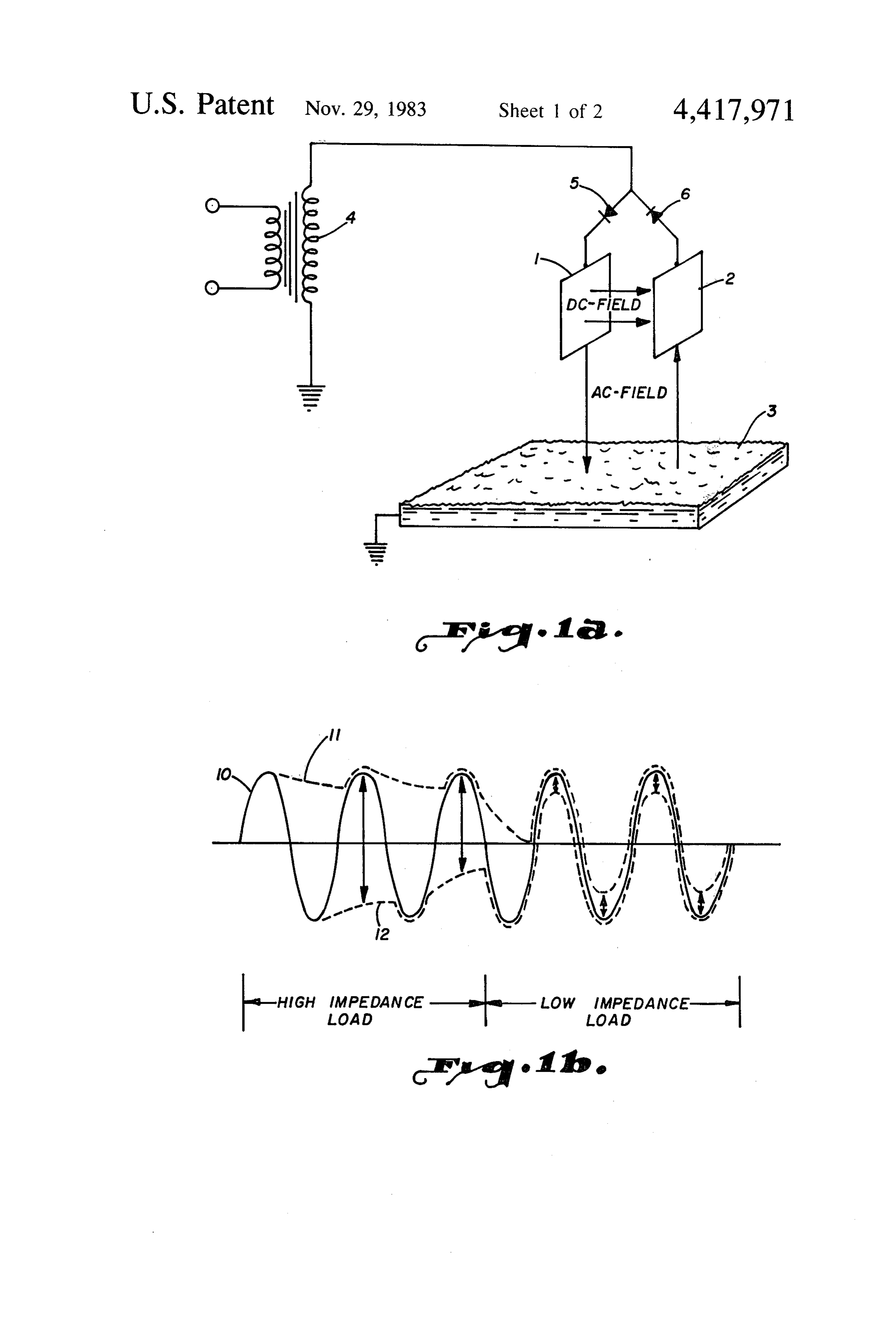
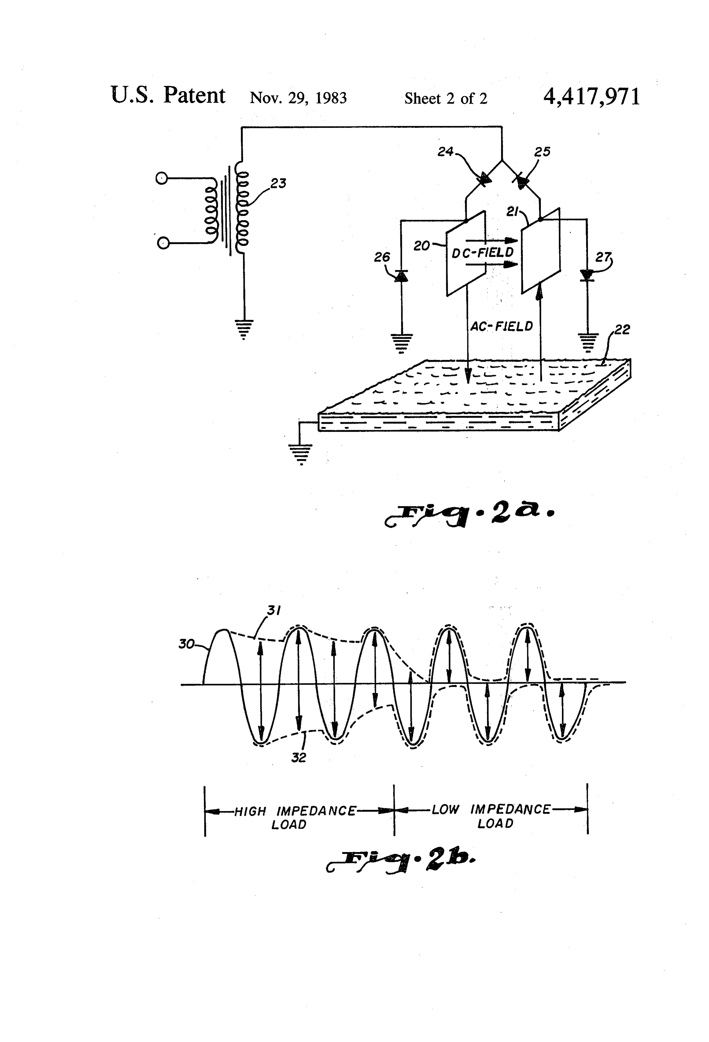
reference. The two incorporated disclosures are dupli 25 BRIEF DESIGNATION OF THE DRAWINGS cates of each other, their claims separately covering the method and apparatus of their inventions. The general FIG. 1a is a schematic of a circuit for an electrostatic organization of the disclosures of these two patents is field generator representing the problem met by the followed in the present disclosure. A mixture of oil and present invention;
water represents the medium passed sequentially 30 FIG. 1b is a schematic representation of applied volt through the DC and AC type of electrostatic fields ages in the circuit of FIG. 1a and the voltages appearing generated by the electrodes. The mixture may be more between electrodes of FIG. 1a, generally defined as that of a polar liquid finely dis FIG. 2a is a schematic of the circuit of FIG. 1a em persed and in an immiscible non-polar liquid. Of course, bodying the present invention;
interchangeably, the disclosure can refer to either a 35 FIG. 2b is a representation of voltages in the circuit two-phase mixture of immiscible polar and non-polar of FIG. 2a.
liquids, or a mixture of oil and water. In both events, the problem arises with the reduction in the dielectric BEST MODE FOR CARRYING OUT HE strength of these mixtures. The effectively AC electro INVENTION static field is generated between the electrodes and the 40 NOMENCLATURE ground reference, while the second electrostatic field is maintained between the electrodes. The mixture of The disclosure carefully characterizes the medium in liquids is first flowed through the AC type of field and, which electrostatic fields are sustained between secondly, through the DC field for progressive coales charged electrodes. Note that the broadest description cence of the dispersed liquid droplets. refers to a mixture of two liquids which are immiscible Subsequent to the formation of the disclosures of the relative to each other, one liquid being more polar than incorporated patents, emulsions have been discovered the other. The mixture is referred to as an emulsion. In as having variable dielectric strengths. This mode of the oil field, an emulsion of oil and water is common. expression contrasts with the previous reference to Oil and water fall into the category of two liquids varying electrical conductivity of the emulsions. It now 50 which are immiscible relative to each other, the water appears more appropriate to use the term dielectric being the more polar and dispersed in the form of drop strength as compatible with the characteristics of the lets within the less polar oil.
electrostatic fields. The rectifier has been a unit of electric circuits for There has been a nagging problem in reducing th many years. Recently, the term diode has been applied invention of the incorporated patents to practice. Spe 55 to devices which function as the rectifier functions. cifically, when flowing emulsions of decreasing dielec Further, it has become the practice to refer to a diode tric strength through the two electrostatic fields, the stack as the unit which is essentially a plurality of recti DC electrostatic field between the energized electrodes fiers in series. Those skilled in the art should not be correspondingly decreases to ineffective values. Vari confused between the terms rectifier, diode, and diode ous arrangements to maintain the strength of the DC stacks, as they are all electrically equivalent and can be field have been employed, but no arrangement has satis designated with a common symbol.
factorily obviated the simultaneous loss of AC field THE PROBLEM strength. Fortunately, there is prior art which exempli fies the inadequate solution to this problem. The disclosures of the incorporated patents have been U.S. Pat. No. 4,049,535 discloses one arrangement to 65 successfully reduced to practice for years as the so maintain the DC field while the load impedance of the called dual polarity circuit. The dual polarity circuit has emulsion is low. However, the addition of the full-wave functioned successfully to coalesce droplets of water rectifier, utilizing a grounded center-tap transformer, dispersed in oil. However, a problem has slowly crystal 5 lized in the applications of the dual polarity circuit electrodes 1 and 2. Essentially, during the last two cy where the oil treated is relatively heavy and its emulsion cles of applied voltage, when the dielectric strength has a relatively high proportion of water. Thus far, the between electrodes 1 and 2 deteriorates to a relatively problem has appeared in relatively infrequent instances, low value, the voltage on the undriven electrode of 1 but its appearance has generated the present invention. and 2 closely follows the voltage on the driven elec FIGS. 1a and 1b are offered to disclose and emphasize trode. With the driven and undriven electrode voltages the emerging problem experienced with the actual re closely following each other during the last two cycles duction to practice of the circuit of the incorporated of the voltage applied to them, the DC voltage appear patent disclosures. Electrodes 1 and 2 are spaced from ing between the two electrodes is represented by the each other and immersed in the liquid mixture. A third O small, vertical distance between the two electrode volt electrode 3 is constructively formed as the upper sur ages. The result is that the DC electrostatic field deteri face of the body of relatively polar conductive liquid orates to such a low value that it becomes ineffective to below the electrodes 1 and 2 which has been coalesced coalesce the polar liquid dispersed in the non-polar from the mixture. Energized by transformer 4, the ar liquid. The voltage of the positively charged electrode rangement of the electrodes 1, 2 and 3 are familiar from 15 actually passes through Zero voltage and is negatively the disclosures of the incorporated patents. charged for a portion of each applied voltage cycle. The AC form of electrostatic field generated between Similarly, the voltage of the negatively charged elec the lower ends of electrodes 1 and 2 and surface elec trode actually passes through Zero voltage and is posi trode 3 is a feature familiar from the incorporated dis tively charged for a portion of each voltage cycle. It is closures. At the same time, the DC electrostatic field is 20 an object of the present invention to supply a circuit in generated between electrodes 1 and 2. The liquid mix the network disclosed in FIG. 1a which will limit the ture flows sequentially through the AC type of field and voltage of an undriven electrode of 1 and 2 so that it the DC field so that the two electrostatic fields may will not follow the voltage of the driven electrode be effectively coalesce the droplets of polar liquid to a size yond zero, or ground potential. This novel circuit in which will enable them to gravitate into and join the 25 sures that there will always be at least transformer volt lower body of liquid having surface 3. ; : age between the electrodes, within the power output The electrodes 1 and 2 are connected in parallel to limits of the transformer, during the period of low impe transformer 4, the separate connections containing op dance between the electrodes. In the preferred embodi positely poled rectifiers 5 and 6, as symbolized in FIG. ment, the circuit addition incorporated will not allow 1a. The AC voltage applied from transformer 4 devel 30 either electrodes 1 or 2 to reverse polarity. The voltage ops the two electrostatic fields with strengths depend on the undriven electrode is clamped to Zero, or ground ing upon the dielectric strength of the mixture. The potential, if the voltage attempts to reverse its polarity. problem met by this disclosure develops when this di electric strength, and consequent impedance of the EMBODIMENT OF THE INVENTION mixture, decreases to a value which yields the results 35 FIG. 2a discloses a circuit generally similar to that of charted in FIG. 1b. FIG. 1b is, essentially, a chart of the FIG. 1a. Electrodes 20 and 21 are spaced from each voltage variations in the circuit of FIG. 1a. The AC other. in the stream of liquid mixture processed by the voltage of the transformer 4 is represented by sinusoidal electrostatic fields between electrodes 20, 21 and sur curve 10. The first two complete cycles shown of this face electrode 22. Electrodes 20 and 21 are connected in applied voltage of curve 10 generate the voltage on parallel to transformer 23 through oppositely poled electrode 1, as represented by curve 11. Curve 12 repre rectifiers 24 and 25.
sents the voltage appearing on electrode 2. The differ FIG.2b is generally similar to FIG. 1b in that it is a ence between curves 11 and 12, therefore, represents chart of the voltage variations of the circuit of FIG.2a the voltage between electrodes 1 and 2 with their DC as embodying the invention. The present invention electrostatic field generated between them. Specifically, 45 embodies the concept of providing an electrical circuit the vertical distance between curves 11 and 12, during with low impedance to ground when the voltages on the first two cycles of the applied voltage of curve 10, electrodes 20 and 21 attempt to reverse their intended represent the value of this DC voltage when the dielec polarity. To preferably embody the invention, rectifier tric strength of the liquid mixture between the elec 26 is connected between electrode 20 and ground, and trodes is relatively high. This explanation is, more or 50 rectifier 27 is connected between electrode 21 and less, a review of the disclosures of the incorporated ground potential. Oriented as symbolized in FIG.2a, patents to dramatically illustrate the appearance of the these rectifiers function to limit the potential, relative to nagging problem brought about by a significant de ground, of each non-driven electrode to zero as a poten crease of the dielectric strength of the fluid medium tial of opposite polarity is applied to the driven elec between electrodes 1 and 2. 55 trode.
It is to be noted that the first two cycles of the voltage The voltage chart of FIG. 2b shows the first two curves in FIG. 1b may be described as normal opera cycles of applied sinusoidal voltage represented as tion. The curves have been extended to form the subse curve 30, while the electrode voltages are 'represented quent two cycles in illustration of the problem to be as curves 31 and 32. Of course, the first 2 cycles of solved. Of course, the transition does not take place as applied voltage of curve 30 essentially duplicate the abruptly as illustrated by the lack of transition between voltage patterns of the first two cycles of applied volt the first two cycles and the last two cycles. The con age in FIG. 1b. The last two cycles of applied voltage of mon sense of one skilled in the art permits the juxtaposi curve 30 illustrate the voltage limitation of electrodes tion of the two pairs of cycles to illustrate the problem 20 and 21, as charted by curves 31 and 32. Limited to solved by the invention. 65 zero, or ground, potential when the dielectric strength The last two cycles of the applied voltage of curve 10 between the electrodes is relatively low, the DC poten are displayed with the extensions of curves 11 and 12 to tial between the electrodes is represented by the vertical demonstrate the decrease of the DC potential between distance between curves 31 and 32. In comparison of 6 s 6 this differential with that of the last two cycles of curves a pair of electrodes spaced within a mixture of polar and 11 and 12 of FIG. 1b, there is demonstrated the effec non-polar immiscible liquids, tiveness of the present invention to maintain the DC means for connecting the pair of electrodes and the DC potential to a significant value during the periods when voltage sources such that each of the electrodes has the mixture between the electrodes is of relatively low voltage pulses of one of the sources applied to it to dielectric strength. generate an electrostatic field in which the polar CONCLUSION liquid droplets will coalesce to a size which will cause their gravitation within the non-polar liquid,
The beauty and concomitant simplicity of the inven means for forming a body of the coalesced and gravi tion should now be apparent to those skilled in the art. O tated polar liquid droplets below the pair of elec From a functional standpoint, the invention merely trodes, prevents the potential difference between electrodes 20 and a rectifier connected between one of the electrodes and 21 from collapsing to such a low value that their and ground potential to maintain a differential of DC electrostatic field is ineffective in bringing about coales potential between the electrodes as the proportion of cence. Structurally, the invention is embodied in the 15 polar and non-polar immiscible liquids of the mixture circuit provided by connecting rectifiers 26 and 27 be changes to reduce the dielectric strength of their tween electrodes 20 and 21 and ground potential. Of mixture.
course, these rectifiers are poled oppositely of each 2. The system of claim 1, in which, other and reverse biased when the associated electrode the sources of DC voltage pulses include a transformer is driven to provide the required function to carry out 20 energized by AC voltage and two oppositely poled the invention. FIG. 2a discloses the complete circuit, or rectifiers connected to said transformer, and wherein electrical network, in which the invention is embodied, said means for connecting includes a connection be and the voltage chart of FIG.2b dramatically discloses tween each of said rectifiers and one of said elec the limitation imposed upon the electrode voltages to trodes.
maintain the differential required. 25 3. A system for coalescing water which is dispersed in It is not to be overlooked, when measuring the the form of droplets throughout a second liquid, includ breadth of the invention, that there is invention in con Ing, necting one of the electrodes to ground through a single at least one pair of electrodes spaced from each other rectifier. Thus, with at least one of the electrodes con within a mixture of water dispersed in the form of nected to ground potential through a rectifier, as dis 30 droplets throughout a second liquid, closed in the drawings, a significant DC potential will a body of water spaced below one of the electrodes and be maintained between the electrodes when the dielec connected to ground potential, tric strength of the mixture between the electrodes is at a transformer energized by AC voltage for supply of a low ebb. The breadth of the invention is, thus, defined electrical potential to the electrodes, while the preferred embodiment utilizes a rectifier cir 35 a first electrical connection between the secondary of cuit for each of the two electrodes. the transformer and ground potential, From the foregoing, it will be seen that this invention a second electrical connection between the secondary is one well adapted to attain all of the ends and objects and one of the pair of electrodes controlled by a first hereinabove set forth, together with other advantages rectifier, which are obvious and inherent to the apparatus. a third electrical connection between the secondary and It will be understood that certain features and sub the other of the pair of electrodes controlled by a combinations are of utility and may be employed with second rectifier oppositely poled from the first recti out reference to other features and subcombinations. fier,
This is contemplated by and is within the scope of the and two rectifiers with each connected between one of invention. 45 the two electrodes and ground potential with the two As many possible embodiments may be made of the rectifiers being poled to maintain a predetermined invention without departing from the scope thereof, it is minimum DC potential between the electrodes as the to be understood that all matter herein set forth or proportion of water in the mixture increases to re shown in the accompanying drawings is to be inter duce the dielectric strength of the mixture. preted in an illustrative and not in a limiting sense. 50 4. The system of claim 3, in which, We claim: the first electrical connection is between one end of the 1. A system for coalescing droplets of a relatively secondary and ground potential and the second and polar liquid which are finely dispersed within a body of third electrical connections are between the other an immiscible relatively non-polar liquid, including, end of the secondary kandsk the*k electrodes. at least two sources of DC voltage pulses, 55 k
Provenance
- Collection
- Patents citing this work
- Pages
- 6
- Method
- pdftotext (the PDF's own text layer) + pdftoppm 300dpi page scans
- Patent office record
- patents.google.com →
- Source
- Google Patents citing-documents table
- Assignee
- Combustion Engineering, Inc.
- Published
- 1983-11-29
- Transcribed from
- patentimages.storage.googleapis.com →