

patent · US4421078A
Oil changing system
20 December 1983
Text
Page 1bibliographic recordscan →
United States Patent (19) 11 4,421,078 Hurner Dec. 20, 1983 OIL CHANGING SYSTEM 3,638,031 1/1972 Honda et al. ................... 123/96 R
Inventor: Erwin E. Hurner, 413 Valley Ave.,
Moorhead, Minn. 56560 FOREIGN PATENT DOCUMENTS
2 No.: 218.918 AD 21 App O s 1 148109 5/1963 Fed. Rep. of Germany ........ 123/73 22 Filed: Dec. 22, 1980 AD 503450 of 1956 Italy ............................... 123/73 AD
Related U.S. Application Data 720222 12/1954 United Kingdom.
1980, abandoned. Primary Examiner-Charles J. Myhre
Assistant Examiner E. Rollins Cross
Attorney, Agent, or Firm-Bailey & Hardaway
58 Field of Search ........... 123/510, 514, 515, 196 R, 57 ABSTRACT 123/196 S, 73 AD, 1 A; 184/6.5, 53 The invention is designed for use with a diesel engine in over-the-road trucks and periodically extracts a given References Cited quantity of oil from the oil pan of the engine and injects
1,352,123 9/1920 Green .................................. 123/515 the regular fuel. In turn, an automatic oil level sensing 2,539,604 1/1951 Woolley ... 23/196 S device keeps the proper level of oil in the pan thus 2,792,912 5/1957 Kangas ...... ... 123/196 S ensuring a constant infusion of fresh oil into the engine's 3, 114,356 12/1963 Werner et al. ................ 123/73 AD oil supply as well as a periodic purging of old oil. 3,137,285 6/1964 Ausserbauer . ... 123/73 AD 3,447,636 6/1969 Bonfilio ..... ... 123/196 R 3,561,565 2/1971 Woor ............................. 123/196 R 11 Claims, 1 Drawing Figure
a222a r FROM * 22- & af
a/aaSaal-62/6 zé FUEl
2624 92 as ay2MAAA
eateSoft fir:SSES 7va 2 o/a 2 a06/Maas
22 as - 7 - / apaS77661 as
a/AA 66 / th. ... Jill. l
aaya e2 a/Z awaas
(246.242&SZY Zola) 2/asy/aa sawsae 22
Drawings
Page 2drawing sheetscan →
Page 3scan →
which is attached to the impulse timer mentioned
Provision is also made for pressurizing and depressur
RELATED APPLICATIONS izing the oil reservoir in such a manner as to prevent the This application is a continuation-in-part of my appli spewing of oil and to retain the cap of the reservoir. cation, Ser. No. 192,077, filed Sept. 29, 1980 now aban These and other objects and advantages of the inven doned. The disclosure therein is hereby incorporated by tion will become readily apparent as the following de reference. scription is read in conjunction with the accompanying drawing wherein like reference numerals are used to
BACKGROUND OF THE INVENTION 10 refer to the views.
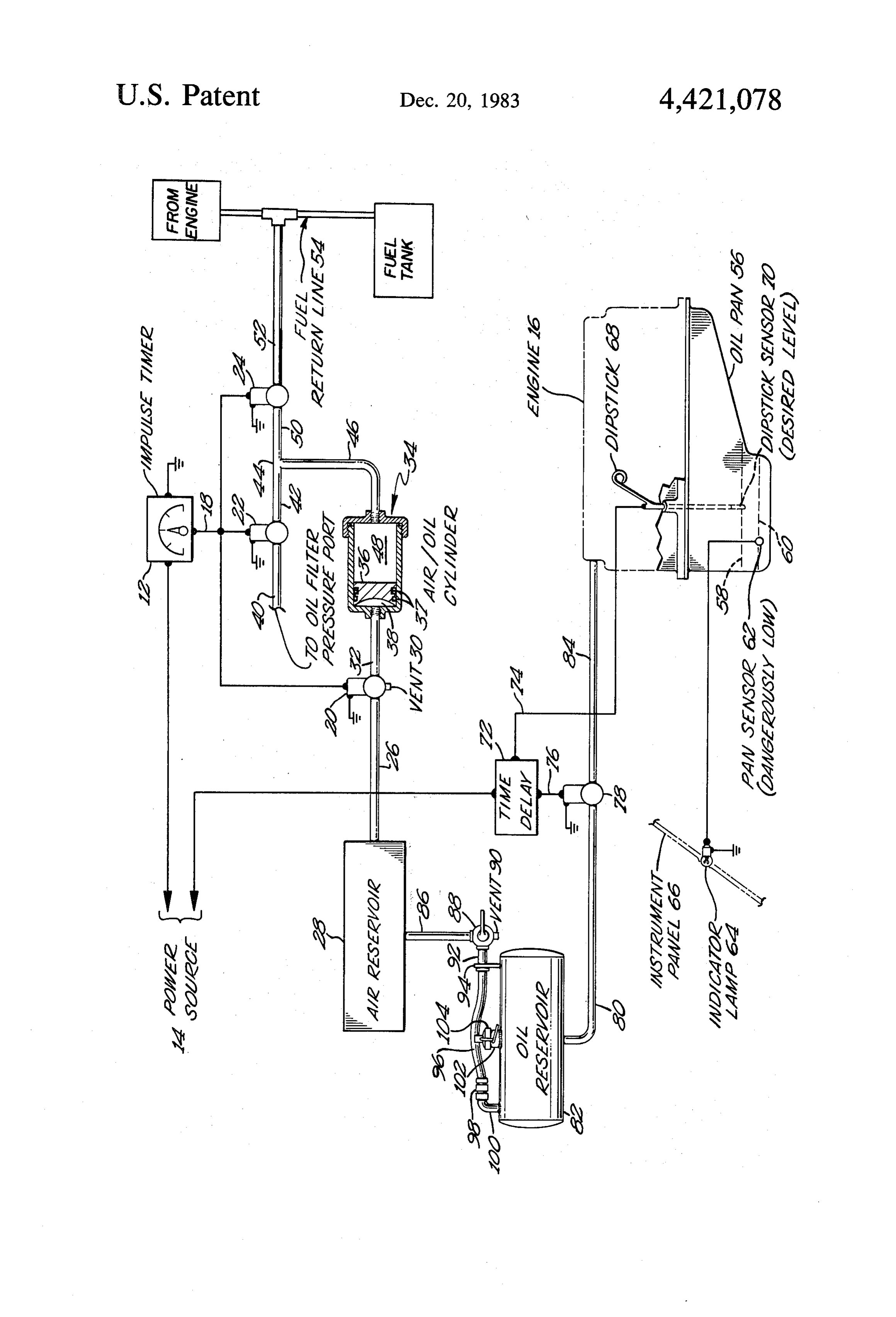
In the field of over-the-road trucking, it is highly BRIEF DESCRIPTION OF THE DRAWING desirable to be able to minimize the amount of service The single FIGURE of Drawing schematically illus required on a vehicle in order that that vehicle be avail trates the invention.
able for use on the road. The changing of oil and corre 15 sponding filter accounts for a substantial portion of the DETALEED DESCRIPTION maintenance which will be performed on an over-the In accordance with this invention an oil changing road truck during its lifetime. Further, the service life of system is provided whereby predetermined amounts of a diesel engine is directly related to the cleanliness of lubricating oil are removed from an engine lubrication the oil run in the engine. 20 system at periodic intervals. The periodic intervals are Thus, it is an object of this invention to provide a established such that the entire contents of lubricating device which will substantially reduce the amount of oil within the lubrication system are removed from the maintenance time required in changing the oil on an lubrication system during a period of time correspond over-the-road truck as well as any diesel powered vehi ing to a normal oil change interval. The lubricating oil cle and which will provide for the oil to remain substan 25 removed from the lubricating system is deposited with tially clean and effective. diesel fuel and thus consumed by the combustion
Summary of the invention
thereof in the diesel engine. The lubricating oil removed from the lubricating system is replaced so as to maintain
In accordance with this invention an oil changing a desired oil level by either conventional means or pref. system is provided whereby predetermined amounts of 30 erably by the means described and claimed in my above lubricating oil are removed from an engine lubrication referenced copending application. Further description system at periodic intervals. The periodic intervals are will be given with reference to the FIGURE of Draw established such that the entire contents of the lubrica 1ng.
tion system are removed during a mileage interval cor 35 The oil changing system in accordance with this responding to a normal oil change interval. The lubri invention is schematically illustrated in the FIGURE of cating oil removed from the lubricating system is depos Drawing. An impulse timer 12 is connected to a power ited with diesel fuel and thus consumed by the combus ignition source 14. The power source 14 is the equivalent of the tion thereof in the diesel engine. The lubricating oil source 14system in a key-operated vehicle and thus removed from the lubricating system is replaced so as to only when the engine 16impulse and similarly timer 12 are activated of the vehicle is running. Im maintain a desired oil level by either conventional pulse timer 12 is set to produce means or, preferably, by the means described and seven seconds) impulse of powera short (approximately periodically through claimed in my copending application below referenced. lead 18 to solenoid valves 20, 22 and 24. The input side To this end, a small oil extractor pump is mounted to of first solenoid valve 20 is connected by line 26 to an the oil output off the oil filter of a diesel engine. The 45 air reservoir 28. The output of first solenoid valve 20 is output of the pump is directed to the fuel tank of the engine for burning along with the conventional diesel aconnected via line 32 to air/oil cylinder 34. Valve 20 is three-way valve and in the non-energized position fuel. Operation of the pump is signalled by an impulse connects timer which is in turn connected to the ignition of the side 38 ofoutput line 32 to vent 30 and thus vents the air cylinder 34 and allows piston 36 and cylinder vehicle. The impulse timer is set so that the oil extractor 50 to assume the position shown in the drawing. When pump is cycled periodically during vehicle operation to 34 direct a predetermined amount of engine oil out of the solenoid valve 20 is energized, lines 26 and 32 are con nected thereby pressurizing the air chambers 38 of cyl oil pan and into the fuel tank. inder 34 and forcing piston 36 towards the right of In an embodiment described and claimed in my co cylinder 34. Second solenoid valve 22 is normally open pending application, Ser. No. 401,533, filed July 26, 55 in its non-energized state and connects a source of en 1982, an oil level sensor is provided in the oil pan of the gine pressurized oil 40 to the input of solenoid valve 22. engine to sense when the oil level has fallen below a This source of pressurized oil 40 may be the output from predetermined point. The sensor is in turn connected to the oil filter on the engine. The output 42 of solenoid a solenoid valve which selectively allows oil from a valve 22 is connected to T-fitting 44 which is connected reservoir to be directed into the oil pan and/or other on one side via conduit 46 to the oil chamber 48 of portion of the oil system of the truck so as to maintain air/oil cylinder 34.
the oil level at the predetermined point. The oil reser The third solenoid valve 24 is of the normally closed voir is desirably pressurized by the air reservoir which type and the input 50 of valve 24 is connected to the is present on most over-the-road trucks as part of the remaining branch of T-fitting 44. The output 52 of third braking system. Such pressurization allows the oil reser 65 valve 24 is connected to the fuel return line 54 or may voir to be located at any height relative to the engine of be routed directly to the fuel tanks if so desired. the truck. The existing air reservoir also serves to actu This concludes the description of the components in ate the oil extractor pump by way of a solenoid valve the oil removing portion of the apparatus in accordance 4 with this invention. As a preferred feature, the oil which is secured by a cam-loc fitting 102 of the type within the lubrication system is replaced by the oil re well known in the art. The length of hose 96 is such that plenishing system described below. However, the lid 104 may not be removed from reservoir 82 without means for maintaining a predetermined oil level may be fitting 98 being disconnected. This serves to restrain lid a conventional oil addition port. The oil addition system 104.
described below is claimed in my copending application OPERATION OF PREFERRED OIL LEVEL above referenced.
Engine 16 generally has an oil pan 56. Shown in phan MAINTENANCE MEANS tom on oil pan 56 are the desired oil level 58 and the When the vehicle is started, power source 14 is ener dangerously low level 60. The desired level 58 is that 10 gized along with impulse timer 12. After a predeter level at which it is desired to maintain the oil level in the mined period of time, impulse timer 12 energizes sole engine. The dangerously low level 60 is that level at noid valves 20, 22, and 24. At that time, valve 22 closes which, if reached, operation of the vehicle should im and valves 20 and 24 are opened thereby allowing the mediately cease until the oil has been brought to a air from air reservoir 28 to pass through lines 26 and 32 proper level. A sensor 62 is located in oil pan 56 at the 15 and into air chamber 38 of cylinder 34. Thence, piston dangerously low level 60. This sensor is then connected 36 is pressed to the right of the FIGURE thereby forc to an indicator lamp 64 on the instrument panel 66 ing the oil in oil chamber 48 through passage 46, junc which will serve to instruct the operator to immediately tion 44, line 50 and 52 to the fuel return-line 54. After shut the engine down. The normal dipstick in the engine approximately seven seconds of being energized, im is replaced by a dipstick sensor 68, wherein the dipstick 20 pulse timer 12 shuts off thereby opening valve 22, clos is formed of a spiral wound material with a hollow core ing valve 24 and causing valve 20 to move to the vent leaving room for a wire to run downward to the sensor position whereby the pressurized oil from the system 70 located at the bottom thereof. This use of the dipstick forces piston 36 to the position shown in the FIGURE as an oil sensor allows very precise location of the de and air in air chamber 38 in line 38 is vented through sired level 58 in the engine. Such location which is 25 vent 30 to the atmosphere. Thus, this portion of the formed by comparing dipstick 68 to the regular dipstick system is ready for the next cycle.
removed from the engine while giving much more ac Everytime the engine is turned off, after a delay of curate level 58 as opposed to attempting to drill pan 56 approximately two minutes in which time the oil has a for a sensor similar to sensor 62. Sensor 70 is connected chance to drain back into oil pan 56, time delay unit 74 to time delay unit 72 by means of leads 74. Time delay 30 activates dip stick sensor 70. If sensor 70 senses the unit 72 activates sensor 70 approximately two minutes presence of oil at the desired level 58, nothing further after engine 16 has been shut off. This allows time for oil happens. Should sensor 70 not detect oil, delay unit 72 in the engine to drain back to pan 56 thereby allowing a activates and opens solenoid valve 78, thereby allowing true reading of the level to be obtained. After this two oil to flow from oil reservoir 82 through lines 80 and 84 minute interval, sensor 70 is activated for approximately 35 and into engine 16. This continues until sensor 70 de seven minutes thereby allowing sensor 70 to sense tects the presence of oil at which time solenoid valve 78 whether the level in the pan 56 has fallen below desired is shut off.
level 58. If the actual level is below the desired level 58, Air reservoir 28 is the conventional reservoir present delay unit 72 activates by means of leads 76 solenoid on most over-the-road trucks for pressurization of valve 78. The intake line 80 of valve 78 is connected to brakes and the like. When it is desired to fill oil reservoir an oil reservoir 82 containing pressurized oil therein. 82, valve 88 is turned to the vent position wherein the The output line 84 of valve 78 leads to the valve cover air pressurizing reservoir 82 is vented through vent 90 or other portion of engine 16 wherein fresh oil may be to the atmosphere. Then, quick-disconnect fitting 98 is added. Of course, when oil has comeback up to desired uncoupled and cam-loc fitting 102 unlatched allowing level 58, sensor 70 will detect that condition and 45 removal of lid 104 for refilling of reservoir 82. It is to be through the time delay unit 72 shut off solenoid valve noted that fitting 98 must be disconnected before lid 104 78. Sensor 70 is activated for approximately seven min may be removed from the reservoir for filling by insur utes in the desired embodiment after the two-minute ing that lid 104 will not be blown off reservoir 82 if delay so as to allow sufficient time for the oil level to be reservoir 82 is pressurized.
brought back to desired level 58 yet not have power 50 OPERATION OF OIL REMOVAL MEANS running to sensor 70 at all times.
Briefly, oil reservoir 82 is pressurized by air reservoir In the preferred embodiment, impulse timer 12 is set 28. Line 86 leads from air reservoir 28 to air valve 88 to activate air/oil cylinder 34 once for every eight min which is a three-way type having a vent 90 and an utes of engine operation, that is, for every eight minutes output 92. Valve 88 is connected via output 92 to 55 that power source 14 is activated. For each cycle of bracket 94 which is fixed to oil reservoir 82 as shown. cylinder 34, approximately 0.8 ounces of oil is extracted Oil reservoir 82 may be a generally cylindrical tank as from the oil pan and delivered to the fuel tank. If the shown and, due to the pressurization as will be more truck averages 35 miles per hour of operation, this sys fully described hereinafter, may be located anywhere tem will result in an effective complete change of oil where there is space about the vehicle. The output line every 9,000 miles with a truck having a 10-gallon oil 92 of valve 88 is attached to a bracket 94 which is in capacity. The use of such a system allows the operator turn attached to the top of reservoir 82. A flexible yet to control precisely the amount of impurities and solids pressure resistant hose 96 connects line 92 to quick-dis suspended in the oil merely by changing the interval on connect fitting 98 of the type commonly used for air which the impulse timer 12 operates. tools and the like which is in turn attached to elbow 100 65 By continually injecting new oil into the engine lubri which leads into reservoir 82. This air line upon open cation system, the additive package present in oils is ing of valve 88 serves to pressurize reservoir 82. Flexi maintained at a desirably high level and at an average ble hose 96 is fastened to the top of a filler cap 104 level higher than that which will result from the normal 5 change-type cycle. Further, by burning used oil along 5. The oil changing system of claim 4, said level main with the conventional diesel fuel, the full heat value of taining means further comprising an oil reservoir re the used oil is extracted. In summary, the instant inven sponsive to said sensing means. tion allows near maintenance-free operation of the oil 6. The oil changing system of claim 5 wherein said oil system of the truck with only a very occasional check reservoir is pressurized.
on the reservoir to make sure that it is up to the desired 7. The oil changing system of claim 6, said system level. further comprising a valve, said valve comprising: While the preferred embodiments of the present in an inlet connectable to a source of pressurized air; vention have been described, it should be understood O a ventan outlet connected to said oil reservoir; that various changes, adaptations and modifications to the atmosphere;
may be made therein without departing from the spirit an open position connecting said inlet and said outlet; and of the invention and the scope of the appended claims. a closed position connecting said outlet and said vent. What is claimed is: 8. The oil changing system of claim 7, said system 1. An oil changing system for automatically metering 15 further comprising:
control amounts of engine lubricating oil into the diesel conduit means connecting said valve outlet and said fuel supply of diesel engines as the engine operates, oil reservoir;
comprising: filling means on said oil reservoir; and a fuel tank remote from the engine containing diesel detachable fitting means connecting said conduit fuel oil; 20 means and said oil reservoir, said conduit means an engine lubrication system containing a predeter being attached to said filling means and of such a mined quantity of a lubricating oil different from length as to prevent removal of said filling means said diesel fuel oil and including an oil pan; without detaching said fitting means. 9. The oil changing system of claim 1 wherein said control means for generating a regular, periodic sig 25 control nal at preset time intervals during engine operation, means comprises an impulse timer energized by said time intervals corresponding to a predeter the10.vehicle ignition circuit.
An oil changing system for automatically meter mined oil change interval to provide for desired oil ing discrete amounts of engine lubricating oil into the removal from said engine lubrication system; diesel fuel supply for a diesel engine, comprising: fixed displacement pump means communicating with 30 a fuel tank remote from a diesel engine for containing said engine lubrication system and with said fuel diesel fuel oil;
tank, said pump means being intermittently opera an engine lubrication system containing a predeter ble in response to said signal during engine opera mined quantity of lubricating oil, said lubricating tion for a controlled, limited duration in response oil being different from said diesel fuel oil and to each periodic signal generated to withdraw a 35 including an oil pan;
limited, predetermined amount of said lubricating control means for generating a regular periodic signal oil from said engine lubrication system and to at preset time intervals during engine operation, transport said limited amount into said fuel tank for said time intervals corresponding to a predeter thorough mixing of lubricating oil and fuel oil for 40 mined oil change interval to provide for desired oil subsequent combustion of the resultant mixture in removal from said engine lubrication system; the engine as fuel, said predetermined amount of fixed displacement pump means communicating with lubricating oil withdrawn by said pump means at said engine lubrication system and with said fuel each signal interval and such predetermined inter tank, said fixed displacement pump means being intermittently operable in response to said signal vals being such that said predetermined quantity of 45 during engine operation for a controlled, limited lubricating oil is withdrawn from said engine lubri duration in response to each periodic signal gener cation system over a predetermined lubricating oil ated to withdraw a limited, predetermined amount drain time period; and of said lubricating oil from said engine lubrication means for maintaining a predetermined oil level in system and to direct said limited predetermined said oil pan; 50 amount of said lubricating oil into said fuel tank for whereby lubricating oil removed by said pump means mixing of said lubricating oil and said fuel oil for is replaced and the lubricating oil in said lubrica subsequent combustion thereof in the engine as a tion systems maintains a substantially constant ac fuel, said predetermined amount of lubricating oil ceptable contaminant level and the need for dis 55 withdrawn by said pump means at each signal in crete periodic oil changes is eliminated. terval and such predetermined intervals being such 2. The oil changing system of claim 1 wherein said that said predetermined quantity of lubricating oil means for maintaining comprises means for sensing is withdrawn from said engine lubrication system whether the oil in said pan is at said predetermined over a predetermined lubricating oil drain period; level. whereby upon replenishment of lubricating oil with 3. The oil changing system of claim 2 wherein said 60 fresh lubricating oil a constant, acceptable contam inant level is established and maintained in said sensing means is mounted on the dipstick of the engine. lubricating oil and the need for periodic discrete oil 4. The oil changing system of claim 2 wherein said changes is eliminated.
means for maintaining further comprises time delay 11. The oil changing system of claim 10 wherein said means connected to said sensing means so that oil will 65 engine has an oil filter having an output of clean filtered be added to said oil pan only when said oil level has oil, said predetermined amount being withdrawn from fallen below said predetermined level for a predeter said filter output.
mined period of time. k : k :
Provenance
- Collection
- Patents citing this work
- Pages
- 5
- Method
- pdftotext (the PDF's own text layer) + pdftoppm 300dpi page scans
- Patent office record
- patents.google.com →
- Source
- Google Patents citing-documents table
- Assignee
- Hurner Erwin E
- Published
- 1983-12-20
- Transcribed from
- patentimages.storage.googleapis.com →