

patent · US4023921A
Oil burner for NOx emission control
17 May 1977
Text
Page 1bibliographic recordscan →
United States Patent (19) (11) 4,023,921 Anson (45) May 17, 1977 (54) OLL BURNER FOR NO EMISSION 57 ABSTRACT
CONTROL
Method and apparatus for producing heat from a liquid 75 Inventor: Donald Anson, Los Altos, Calif. fuel in an oil burner with a low NO-gas effluent. A Assignee: Electric Power Research Institute, small relatively higher velocity stream of air is directed Palo Alto, Calif.
concentric about a divergent spray or stream of ignited fuel oil in a primary flame zone in such amount that 22 Filed: Nov. 24, 1975 only a minor portion of the fuel can be combusted in (21) Appl. No.: 634,702 said primary flame zone. The air is directed in such manner as to produce toroidal fluid circulation pattern (52) U.S. C. .................................... 431/9; 431/115 atomizing the liquid fuel and establishing a stable (51) int. Cl”........................................... F23L 7100 flame. A small amount of recirculated flue gas (RFG) is Field of Search ............. 431/8, 9, 10, 115, 116 immediately thereafter introduced concentrically about said primary flame zone in the general direction References Cited of fluid flow. Air is introduced concentrically there UNITED STATES PATENTS about in a secondary flame zone in the fluid flow path of said primary flame zone in at least sufficient quantity 3,620,657 l l 1971 Robinson ............................... 431/9 to burn the remaining combustibles. Oxides of nitrogen 3,817,685 6/1974 Joannes ......... . 4311116 in the resultant effluent are suppressed by adjusting the 3,868,211 2/1975 LaHaye et al. ... 43/10 amount of RFG and hence the flame composition and 3,927,958 12/1975 Quinn ................................ 431/1 16 temperature.
Primary Examiner-Edward G. Favors
Attorney, Agent, or Firm-Townsend and Townsend 10 Claims, 1 Drawing Figure
acapacaaaaa
sizzizza
N SNNNYNYS
Drawings
Page 2drawing sheetscan →
Page 3scan →
substantially reduce the oxides of nitrogen in the efflu
OIL BURNER FOR NO EMISSION CONTROL ent.
Background of the invention
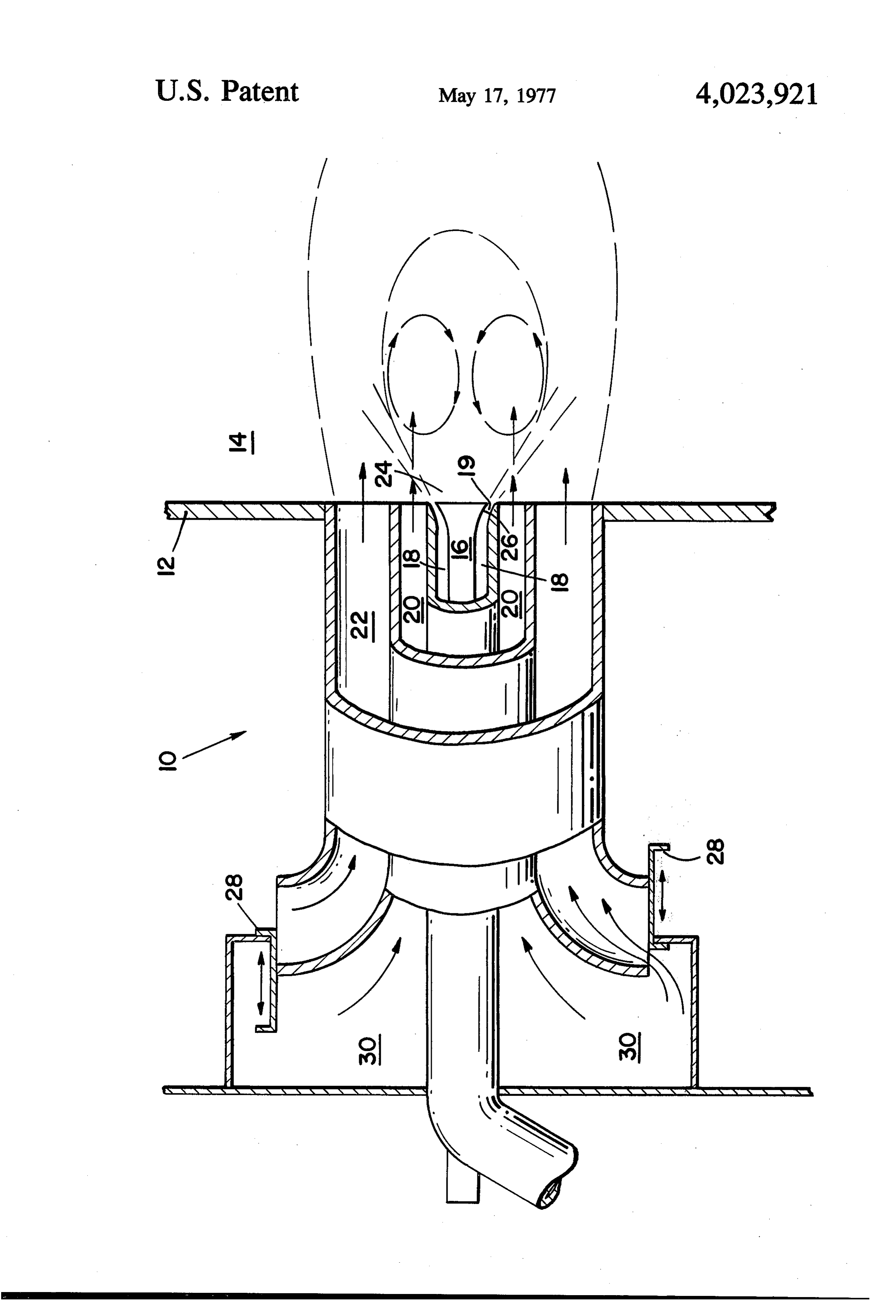
The particular objects and advantages of this inven tion will be apparent after examination of the following 1. Field of Invention detailed description of specific embodiments. This invention relates to methods for burning liquid BRIEF DESCRIPTION OF THE DRAWING fuels in oil burners of furnaces and the like and particu larly to a method for reducing the production of NO The single FIGURE illustrating the invention is a gases while producing a stable flame during combus cut-away section of an oil burner nozzle adapted to tion in an oil burner. 10 operate according to a specific embodiment. 2. Description of the Prior Art DETALED DESCRIPTION OF THE SPECIFIC An oil fuel burner comprises an oil sprayer or atom EMBODIMENTS izer, an air supply and a stabilizer. The sprayer may be a pressure jet system utilizing pressure energy in the oil Referring to the FIGURE, an oil burner nozzle 10 is supply or it may utilize a second fluid (steam or air) to S shown mounted in a furnace wall 12 to direct a flame create a fine dispersion of the oil or to assist the pres nace 14. Aaxial along an burning path into the interior of a fur furnace may have a plurality of oil burners sure jet action. The air supply is essential for combus so a portion may be turned off if less heat output is tion. To ensure rapid mixing of the fuel and air, this air required.
supply is normally in a highly turbulent condition. The 20 An oil burner nozzle in operation defines a combus stabilizer serves to provide, within the turbulent air tion path established by a fluid flow from the burner supply, a quiescent or circulating flow zone in which a nozzle 10, which path comprises a relatively restricted flame may be initiated and maintained. The stabilizer is primary flame zone adjacent the burner nozzle 10 in usually a bluff body positioned within the air flow re gion and shaped to give the required quiescent zone. 25 whichdary the fuel oil is partially combusted, and a secon flame zone which is a relatively long feather sur
A bluff body stabilizer in the combustion zone of a rounding and boiler is subject to damage by radiation and corrosion. zone. All fluid extending entering beyond the primary flame the primary flame zone must
This damage occurs particularly to a stabilizer of a pass through the secondary flame zone along this com burner which is out of service but which is in a hot bustion path.
furnace where other burners are operating. A further 30 The method of combustion according to the inven disadvantage of the bluff body type of stabilizer is that tion is as follows. A divergent conical spray of oil is it necessarily obstructs the main air flow.
NO gases have been identified as a major source of injected higher into the primary flame zone while a relatively velocity annular stream of gas is directed into air pollution in the United States. Oil burners designed the primary flame zone intersecting the divergent coni to inhibit the production of NO gases are known 35 cal spray. The gas stream so provided atomizes or as wherein a jet of oil is introduced into a flame through a centerpassage and flue gas mixed with air is introduced sists in atomizing the oil to form a fluid mixture and provides enough oxygen to ignite the fluid mixture through surrounding passages. U.S. Pat. No. 3,743,471 establishing a stable, but fuel-rich, flame in the primary is an example of one such oil burner requiring a rela flame zone.
tively substantial quantity of flue gas for this purpose. 40 More particularly, however, the high velocity airflow Methods and apparatus for controlling the production in the form of an annular jet around the axis of the of NO gases using flue gas in a fuel oil staged combus distributor induces flow recirculation in front of the tion process are disclosed in U.S. Pat. No. 3,868,211. distributor in the region within the conical path along U.S. Pat. No. 3,880,570 discloses a method of atomiz which the oil is injected; this recirculation provides a ing fuel oil and of utilizing recirculated flue gas to in 45 stabilizing region within which a flame may be initiated hibit the production of NO gases. and maintained without any necessity for a bluff body SUMMARY OF THE INVENTION intruding into the main air flow.
A small annular stream of relatively cool recirculated
According to the invention, fuel oil is injected flue gas (RFG) is thereupon introduced radially outside through a distributor arranged to provide a thin film or 50 the stabilizing region, that is, outside the primary flame spray of oil along a divergent conical path, while a zone. Turbulence draws the RFG into the mixture sub small relatively higher velocity stream of air is directed stantially increasing the molar quantity of the gaseous concentric about the tip of the oil distributor into a effluent from the primary flame zone without materi primary flame zone in such amount that only a minor ally adding to the oxygen supply.
portion of the fuel oil can be combusted in the primary 55 The main airflow is preferably fed into the secondary flame zone. The air so directed intersects the oil spray flame zone by injection parallel to the axis of the to produce a toroidal fluid circulation pattern, atomiz sprayer but radially outside the high velocity fluid flow ing the liquid fuel and establishing a stable flame. A in the primary flame zone. The mixture of gaseous small amount of recirculated flue gas (RFG) is intro effluent and recirculated fluid gas is combined in the duced immediately thereafter concentrically about said 60 secondary flame zone with the main air introduced in at primary flame zone in the general direction of fluid least stoichiometric quantity for complete combustion flow. The fluid effluent continues in a substantially to produce an effluent low in oxides of nitrogen. straight path into a secondary flame zone. Relatively The oil burner nozzle 10 of FIG. 1 is operable ac lower velocity air is introduced concentrically about cording to the method of the present invention. The oil the mixture in a secondary flame zone in at least suffi 65 burner nozzle 10 includes an oil injector 16 for produc cient quantity to burn the remaining combustibles. The ing a divergent conical oil spray, an annular gas passage limited oxygen supply in the primary zone and the 18 with a constriction 19 surrounding the oil injector admixture of RFG limit the flame temperature and 16, an annulus 20 for the admission of recirculated flue 4 gas surrounding passage 18, and an outer annulus 22 blockage. The total auxiliary energy requirements for a for the admission of air surrounding annulus 20. burner, are lower than for second fluid systems using Annular gas passage 18 may include a tip 24 defining Steam. -
An oil burner according to the present invention has a flare 26 or a swirler. The flare 26 or alternatively the particular swirler is operable to divert gas delivered through pas application and advantages in multiple sage 18 into a high velocity fanned pattern wider than burner furnaces where, one or more burners are oper the path of a strictly axial passage. So long as gas is ated discontinuously. For this purpose an oil burner injected through passage 18 at a higher velocity than nozzle is provided having means providing a high veloc the fluids injected through passages immediately adja ity gas stream, adapted for continuous operation during cent thereto and the fluid patterns intersect, a toroidal 10 furnace operation. For example, nozzle 16 may be fluid circulation pattern is established immediately in stream provided with a small, high velocity, continuous air front of injector 16 along the combustion path. Inter the through passage 18 which convectively cools section of the injected gas with the fuel spray assists oil burner parts at all times during furnace opera atomisation. The toroidal circulation pattern promotes 15 tion, particularly at low fuel flow rates and during flame the establishment of a stable flame. Preferably the an shut-off periods when the nozzle tip 24 is subject to nular passage 18 is at a mean radius of between about damage due to the high temperatures within the fur 0.1 and 0.4 of the main air supply annulus 22. nace.
With the above-described construction, the overall Where air is utilized the amount of excess oxygen introduced into the furnace which might interfere with size of the burner is reduced compared with those using 20 combustion bluff body stabilisers since there is less blockage in the or contribute to inefficient operation is main air flow. Since atomization is ensured by the high relatively slight since the gas is introduced in only small velocity auxiliary air supply, it is possible to use a low quantities through the constricted passage 18. pressure oil supply in the distributor or sprayer which Alternatively, an oil burner nozzle may be provided distributor or sprayer need not itself necessarily atom wherein a continuous stream of recirculated flue gas is ize the fuel. . . 25 utilized to provide convective cooling through for ex During combustion the amount of RFG admitted to ample annulus 20. Since RFG is a substantially inert mix with the gaseous effluent of the primary flame zone gas, no excess oxygen would be introduced into the is comparable to the amount of that gaseous effluent. furnace which might contribute to inefficient furnace For example, a range of ratios of about one to about operation.
In addition to the primary objects and advantages of four times is suitable. Generally, however, the com 30 substantially bined amount introduced into the primary flame zone nitrogen in aneliminating the production of oxides of oil burner furnace while producing a does not exceed 20% of the total amount introduced into both the primary and secondary flame zones. The stabilized flame without the necessity of a bluff body temperature of the recirculated flue gas is preferably stabilizer, the methods and apparatus according to the less than about 320°C and generally not less than 120 35 present invention have still further advantages. For C. example, a stable flame may be established in the pri The RFG so utilized to mix with the gaseous effluent mary flame zone utilizing only a small amount of air. of the primary flame zone may function as an inert Therefore, the amount of recirculated flue gas which is required to suppress the formation of NO gases is diluent to absorb a portion of the heat produced in the substantially reduced. This is of particular advantage at primary flame zone and to delay the admixture of oxy 40 gen and nitrogen in air until the fuel-ring gaseous efflu high fuel flow rates and where a large amount of recir entis cooled below the temperatures at which oxides of culated flue gas is not available. The high velocity air stream utilized as a primary nitrogen can be formed.
In a specific embodiment of the method according to flame zone air supply and as a coolant for the oil burner the invention, the high velocity gas stream creating the 45 nozzle may be maintained continuously without inter toroidal circulation pattern may be a stream of air of a fering with combustion or contributing to inefficient volume substantially less than the combined volume of operation in a multiple burner furnace. all fluids along the combustion path. This high velocity A further advantage of the construction described air in the primary flame zone establishing a stable flame 50 above is that burner ancillary components such as is provided in sufficient quantity to supply in the range flame detectors and ignition torches can be housed of approximately 2 to 10% of the stoichiometric oxygen within the high velocity air supply passage 18 and can requirement, and preferably from about 5 to 6% of also be protected from heat.
stoichiometric. As a still further advantage, an oil burner nozzle Since a stable flame is established in the primary utilizing a continuous gas stream can be maintained flame zone using an oxygen-deficient gas supply, the 55 substantially free from soot and the like around the tip control of the burner can be simplified. For example, since the continuous gas stream would substantially the fuel flow rate and the secondary zone air supplies prevent the accumulation of foreign matter. can be varied over a broad range of fuel flow ratios An oil burner nozzle according to the invention may without resultant flame instability. For example, a sta also be provided with damper means 28 to control the ble flame can be maintained to typically at least one 60 ad mixture of air and recirculated flue gas admitted fifth of the predetermined full load fuel flow rate, thus through an annulus 22. The recirculated flue gas is providing a turn-down ratio of at least five-to-one. spheric maintained in a plenum 30 at a pressure above atmo Variations in flow of the high velocity air stream, which through pressure. Therefore, air cannot be admitted is typically between 50 and 150 m/s, do not affect the 65 the upperannulus 20 in the firing position as shown in half of the figure. In the burner "off" posi flow rate of the fuel, as is the case with internal mixing "second fluid' systems making use of an atomizing tion, shown in the lower half of the figure, the damper fluid. The use of a low oil pressure enables large oil may be positioned to pass RFG through both annulus flow passages to be employed with reduced risk of 20 and annulus 22 to ensure burner protection.
Page 5scan →
Specific embodiments of the invention have been flare means adjacent said liquid fuel injection means described. Other embodiments incorporating the es defining an inner portion of said constricted annu sential features of the invention will become obvious to lar passage operable to direct said small annular those of ordinary skill in the art in light of the present high velocity air stream in a fanned pattern admix disclosure. It should, therefore, be understood that all ing with and atomizing said spray of liquid fuel for matter contained in the above description or shown in promoting the establishment of a stable fuel-rich the accompanying drawings will be interpreted as illus flame;
trative and not in a limiting sense. annulus means surrounding said narrow annular gas What is claimed is: passage operable to provide for the admission of 1. A method for producing heat in a liquid fuel 10 recirculated flue gas adjacent to and combining burner while suppressing the production of oxides of with said admixture of liquid fuel and high velocity nitrogen in a flame defining a combustion path with a air, outer annulus means surrounding said recirculated primary flame zone adjacent the tip of a liquid fuel burner and a secondary flame zone substantially sur 15 flue gas annulus means operable to provide atmo spheric air in substantially stoichiometric quantity.
rounding and extending beyond said primary flame zone along said combustion path comprising the steps wherein 6. A liquid fuel burner nozzle according to claim 5 of: said constricted annular passage is adapted to provide continuously injecting a spray of liquid fuel into said nace operation a small continuous stream of gas during fur primary flame zone while directing a relatively high 20 7. A liquid fuel for cooling said nozzle. velocity stream of air in an intersecting manner to wherein said recirculated burner nozzle according to claim 5 create a toroidal fluid circulation pattern such that adapted to provide a continuous flue gas annulus means is the oxygen content of the high velocity air stream is furnace operation for cooling saidstream nozzle. of gas during approximately 5% of stoichiometric, said air 8. A liquid fuel burner nozzle according to claim 5 stream atomizing said liquid fuel to form a fluid 25 wherein mixture, whereby liquid fuel is ignited and a stable provide asaid liquid fuel injection means is adapted to flame is established in said primary flame zone to ment range between aspray continuous of liquid fuel over an adjust predetermined full load fuel flow produce a gaseous effluent, rate and at least onefifth of the predetermined full load introducing recirculated flue gas into admixture with fuel flow rate and wherein said constricted annular gas said gaseous effluent immediately after said pri 30 passage is adapted to provide a constant high velocity mary flame zone to substantially increase the molar quantity of said gaseous effluent from said primary air9.stream A over said adjustment range.
method for producing heat in a liquid fuel flame zone; burner while suppressing the production of oxides of and thereafter combining in said secondary flame nitrogen in a flame, said flame zone said gaseous mixture with air in substantially 35 path having a primary flame zonedefining a combustion adjacent the tip of a stoichiometric quantity for complete combustion.
2. A method for producing heat in a liquid fuel liquid fuel burner and a secondary flame zone substan tially enveloping said primary flame zone and extend burner according to claim 1, wherein recirculated flue ing along said combustion path, said method compris gas having a temperature between approximately 120 Ing:
C. and approximately 320 C is introduced in an 40 injecting a divergent spray of liquid fuel into said amount comparable to the amount of oxygen-contain primary flame zone while simultaneously directing ing gas introduced into said primary flame zone. a stream of oxygen-containing gas concentric 3. A method for producing heat according to claim 2, about and across said divergent spray at a relatively further including the step of introducing recirculated higher velocity than that of said injected spray to flue gas into said secondary flame zone to further dilute 45 atomize said liquid and to create a toroidal fluid the air. circulation pattern, whereby liquid fuel is ignited 4. A method for producing heat according to claim 2, and a stable flame is established in said primary wherein the combined amount of air and recirculated flame Zone, producing a gaseous effluent; flue gas introduced into the primary flame zone is less introducing recirculated flue gas into admixture with than 20% of the total molar amount introduced into 50 said gaseous effluent immediately downstream of both the primary flame zone and the secondary flame said primary flame zone to substantially increase ZOC. the molar quantity of said gaseous effluent from 5. A nozzle for producing a flame suppressing the said primary flame zone; and production of NO gases in a liquid fuel burning fur thereafter combining said secondary flame zone into nace comprising: 55 admixture with air in substantially stoichiometric liquid fuel injection means for introducing a continu quantity for complete combustion. ous spray of liquid fuel into said furnace during 10. A method according to claim 9, wherein the total combustion of said liquid fuel spray; molar quantity of gas flow admitted to said primary a constricted annular gas passage surrounding said flame zone does not exceed about 20% of the total liquid fuel spray injection means for providing a 60 molar quantity of gas flow of said secondary flame small continuous annular stream of high velocity ZO. k k k xk sk air during said combustion;
Provenance
- Collection
- Patents citing this work
- Pages
- 5
- Method
- pdftotext (the PDF's own text layer) + pdftoppm 300dpi page scans
- Patent office record
- patents.google.com →
- Source
- Google Patents citing-documents table
- Assignee
- Electric Power Research Institute
- Published
- 1977-05-17
- Transcribed from
- patentimages.storage.googleapis.com →