

patent · US2935126A
Oil burner
3 May 1960
Text
Drawings
Page 1drawing sheetscan →
Page 2drawing sheetscan →
Page 3scan →
United States Patent Office1.
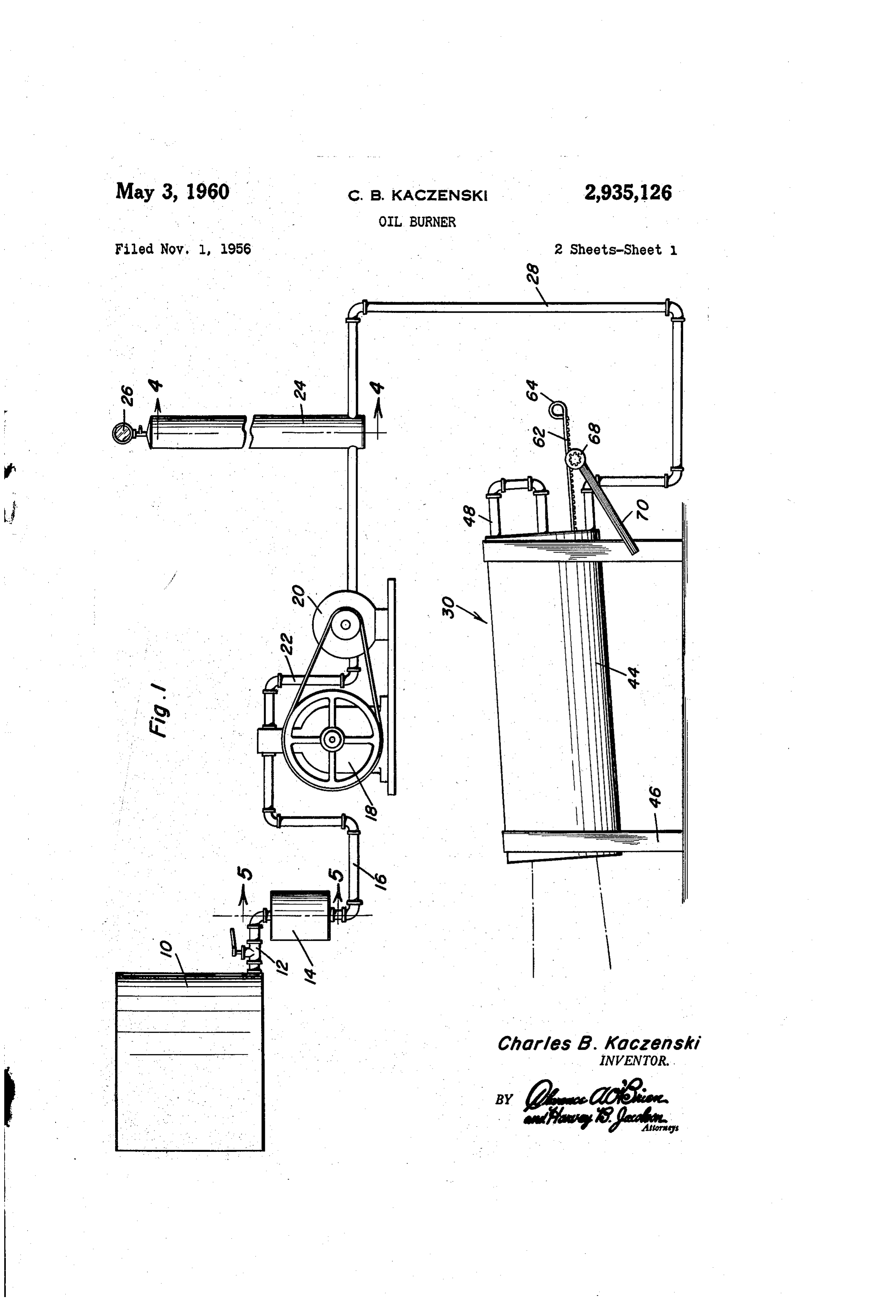
Patented May 3, 1960 stored, the fuel being supplied from this tank through a manual control valve 12 to a gas and oil mixing device 14. From the latter, the mixture of air and oil in an 2,935,126 atomized form is delivered by a pipe 16 to the intake of a compressor indicated generally by the numeral 18 . OL BURNER and which may be driven from a motor or the like 20. Charles B. Kaczenski, Farmdale, Ohio From the compressor the compressed oil and air com ponents of the combustible mixture are delivered by a
Application November 1, 1956, serial No. 619,712 conduit 22, the latter communicating with the bottom of a vertical tank 24 constituting a pressure storage chamber 2 Claims. (Cl. 158-53) providing a reservoir for storing the combustible com ponents under pressure and for eliminating pulsations or surges in the supply of the combustible mixture to the fuel burner. Conveniently, this tank may be pro
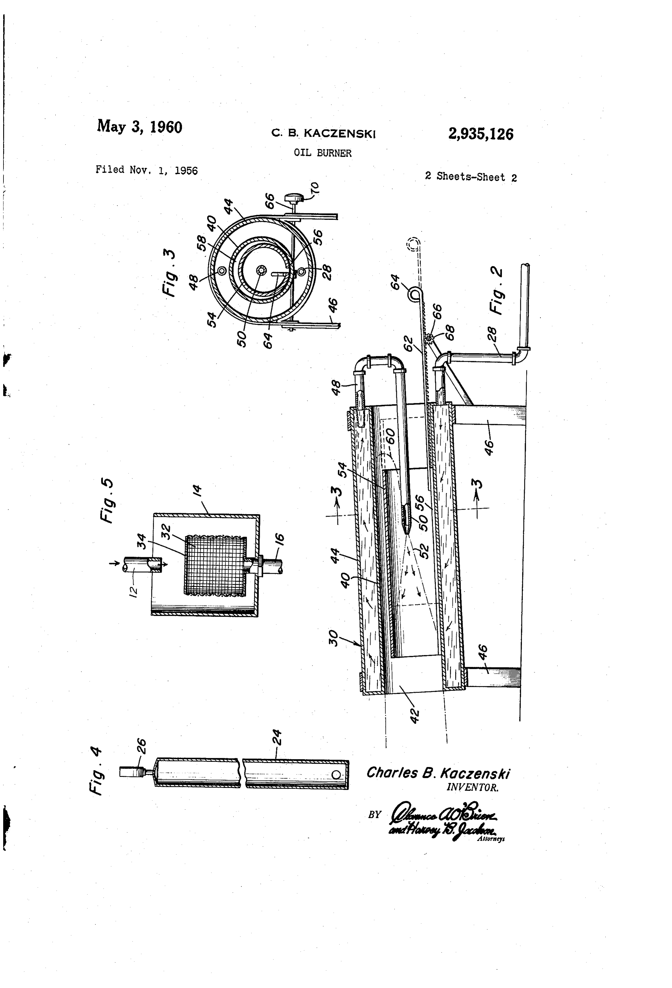
This invention comprises a novel and useful oil burner 15 vided with a pressure gauge such as that indicated at and more particularly relates to a burner adapted to 26. From the tank 24, the combustible components effectively and economically consume refuse oil. under pressure are delivered by the pipe 28 to the oil The primary purpose of this invention is to provide burner forming the subject of this invention and which an oil burner adapted for efficiently utilizing refuse oil is indicated generally by the numeral 30. r as a fuel and other low grades of oil. 20 Referring next to Figure 5, it will be seen that the A further object of the invention is to provide a burner air and gas mixer 14 consists of a receptacle open at its in accordance with the preceding object and which is upper end and into which the valved conduit. 12 dis adapted to supply an economical source of heat for boil charges as shown by the arrows in Figure 5. The dis ing sap and for making maple syrup and the like, also charge conduit 16 connects with the bottom wall of the for operating a steam boiler, drying hay and grain and 25 receptacle 14 and is provided with a screen 32 having for other purposes for which heat is required. an imperforate top wall 34. The arrangement is such A further object of the invention is to provide an oil that the oil entering at the top of the member 14 strikes burner in conformance with the aforementioned objects the top of the plate 34 and passes downwardly around which shall be of a simple, compact and economical con the side of the screen. Air being drawn by the Suction struction, and yet which may be readily adjusted for 30 of the compressor 18, through the conduit 16 draws in regulating the combustion of low grades of fuel oil. this, oil causing the latter to atomize and forming a com Still another important purpose of the invention is bustible air and gas mixture, the ratio of oil to the to provide an oil burner having means for forming a fixed intake of air being controlled by the manual valve combustible mixture of a low grade of refuse oil and 12.
air, for compressing this mixture and supplying the 35 Referring now more particularly to Figure 2, it will same at a constant pressure and rate of flow to an oil be seen that the oil burner 30, comprises a cylindrical burner, and wherein an improved oil burner arrange body 40 which is open at both of its ends and whose ment is provided to preheat the compressed fuel and hollow interior constitutes a cylindrical combustion cham for regulating in ...an- - improved manner the combustion ber. 42. Surrounding the chamber 42 is a cylindrical thereof . - - - - -- - . 40 jacket 44 constituting a pre-heater for the combustible These together with other objects and advantages mixture as set forth hereinafter. Conveniently the body which will become subsequently apparent reside in the 40 and its jacket 44 may be mounted upon supporting details of construction and operation as more fully here legs 46, and preferably the chamber 42 is disposed at a inafter described and claimed, reference being had to slight inclination to the horizontal as shown. the accompanying drawings forming a part hereof, where 45 The conduit 28 for supplying the compressed fuel in like numerals refer to like parts throughout, and in mixture communicates with one end of the jacket 44
Figure 1 is a partly diagrammatic view showing in ele which thus constitutes a preheater for the combustible mixture. Preferably this communication of the conduit vation an oil burner in accordance with this invention, 28 is at the bottom portion of the jacket, and a conduit together with a means for forming a combustible mixture 50 48 communicates with the upper portion of this jacket and supplying the same to the oil burner; for delivering the preheated combustible mixture to a Figure 2 is a vertical central longitudinal sectional fuel discharge nozzle. 50 disposed in the interior of the view through the oil burner shown in Figure 1; chamber 42 through the open inlet end of the same. Figure 3 is a vertical transverse sectional view through The nozzle 50 preferably discharges the compressed com the oil burner, taken substantially upon the plane indi 55 bustible mixture in the form of a conical spray 52 as cated by section line 3-3 of Figure 2; indicated in Figure 2.
Figure 4 is a view in vertical section taken substan In order to regulate and control the combustion and tially upon the plane indicated by the section line 4-4 the combustion flame within the combustion chamber of Figure 1 and showing the internal construction of an 42, there is provided a sleeve 54. This sleeve is prefer expansion chamber forming a part of the system; and 60 ably formed with a longitudinal slot or split 56 along its Figure 5 is a rear vertical section taken substantially upon the plane indicated by the section line 5-5 of bottom wall providing for expansion and contraction of said sleeve and the sleeve is adapted to rest at the longi
Figure 1 and showing a gas and oil mixer forming a tudinal edges of the slot or split 56 upon the bottom wall part of the combustible mixture supply means. - of the combustion chamber 42 for sliding movement The oil burning system in accordance with this inven 65 therealong. As will be apparent from Figures 2 and 3, tion is adapted to utilize with a high degree of efficiency the sleeve is of less diameter than that of the combustion a low quality of refuse or low grade oil as a fuel, as chamber 42 so that a space or chamber 58 is provided be for example, a mixture of 50 parts of crankcase oil with tween the side and top walls of the sleeve and the cor 10 parts of furnace oil. responding walls of the combustion chamber. This space Referring first to Figure. 1, it will be seen that the 70 is employed for a purpose to be now described. numeral 10 designates generally a storage tank in which When the combustible mixture discharged from the the low grade of refuse oil to be employed as a fuel is nozzle 50 into the sleeve 54 in the combustion chamber
Page 4scan →
42 is ignited in any suitable manner, the combustion said chamber and adapted to contain a combustible fuel products are discharged from the open end of the com mixture of oil and air under pressure, a burner nozzle bustion chamber shown at the left of Figure 2. The extending into the other end of said chamber to direct velocity of flow from the nozzle 50 together with the ex a flame out of said discharge end of said chamber, means pansion of the combustion products causes a draft or 5 for feeding fuel mixture under pressure from said jacket flow through the sleeve 54 from the right to the left end to said nozzle to cause a flame to be directed from said of the same. This, in turn, causes a recirculation of nozzle at high velocity, an open ended flame control sleeve of smaller diameter and shorter than said chamber dis some of the products of combustion from the chamber 42 to the previously mentioned space between the sleeve posed longitudinally in said chamber and spaced from and the wall of the combustion chamber, and into the O said body and surrounding said nozzle with a flame dis open right hand end of the sleeve as indicated by the charge end facing the discharge end of said chamber, dotted line 60. This recirculation of products of com. said control sleeve having its ends spaced inwardly from bustion insures a more complete and a more intense the ends of said chamber whereby flame directed from said combustion of the oil. nozzle at high velocity and issuing from the discharge end It will now be evident that by sliding the sleeve upon of the control sleeve will cause a differential in pressure the bottom wall of the combustion chamber longitudinal in said chamber at the ends of the control sleeve resulting ly thereof, the shape of the flame of combustion and the in an aspirating effect causing a recirculation of the flame extent of recirculation of combustion products can be and products of combustion from the discharge end of readily regulated and controlled. Means are provided for the control sleeve through the space between said body adjusting the position of the sleeve. For this purpose there 20 and control sleeve and into the other end of said control is provided a rack bar 62 which is secured to the interior sleeve, said control sleeve being longitudinally split for of the sleeve at the bottom wall of the same and extends expansion and contraction and having longitudinal edges from the right hand end of the sleeve and through the at said split slidably resting on the bottom of said body right hand end of the combustion chamber to the exterior for sliding adjustment of the control sleeve relative to of the latter, being provided with a finger-grip portion 64 25 said nozzle to control the shape of the flame and the ex whereby the sleeve may be manually adjusted. There tent of recirculation of said flame and products of com is also provided a shaft 66 having thereon a gear 68 bustion. . .. registering with the rack bar 62, whereby upon rotation 2. The combination of claim 1, and means for adjust of the handle 70 sliding movement may be imparted to ing said control sleeve comprising a rack bar fixed to said 30 sleeve and extending therefrom out of one end of the
The foregoing is considered as illustrative only of the combustion chamber, and a crank operated gear meshing principles of the invention. Further, since numerous with said rack bar for moving the rack bar longitudinally. modifications and changes will readily occur to those References Cited in the file of this patent skilled in the art, it is not desired to limit the invention to the exact construction and operation shown and described, 35.
and accordingly all suitable modifications and equiva
United states patents,
lents may be resorted to, falling within the scope of the 1,465,797 Wiederwax ------------ Aug. 21, 1923 invention as claimed. 1,509,706 Bryan et al. ------------- Sept. 23, 1924 What is claimed as new is as follows:
1. An oil burner comprising a body having a straight 40 1,530,831 open ended, cylindrical combustion chamber providing for 2,499,207 Wolfersperger --------...- Feb. 28, 1950 uninterrupted straight line flow therethrough and having 2,701,608 Johnson ----------was own win Feb. 8, 1955 a discharge end, a fuel preheating jacket surrounding 2,857,961 Brown et al. ------------ Oct. 28, 1958
Provenance
- Collection
- Patents citing this work
- Pages
- 4
- Method
- pdftotext (the PDF's own text layer) + pdftoppm 300dpi page scans
- Patent office record
- patents.google.com →
- Source
- Google Patents citing-documents table
- Assignee
- Charles B Kaczenski
- Published
- 1960-05-03
- Transcribed from
- patentimages.storage.googleapis.com →