

patent · US3319692A
Oil burner
16 May 1967
Text
Drawings

Page 1drawing sheetscan →
Page 2drawing sheetscan →
Page 3scan →
United States Patent Office 3,319,692 Patented May 16, 1967
3,319,692 downstream along the surface of revolution and acts as a ORAL BUERNER pump to entrain a relatively high percentage of recir Imants Reba, Chicago, I., and Paul W. Cooper, Abi culated products of combustion. These products, along querque, N. Mex., assignors to IT Research Institute, with primary air, are directed past the sclid of revolution Chicago, Ill., a corporation of irois into a mixing chamber where they are mixed with atomized Filed June 1, 1965, Ser. No. 460,054 oil from a high pressure oil nozzle. The intermixed oil, 8 Claims. (CI. 158-1) air and recirculated combustion products pass into the combustion
The present invention relates to oil burner devices and in an efficient zone where, upon ignition, they are burned is, more particularly, concerned with the provision of a 10 gases are, preferably manner. A portion of the combustion simple, compact burner unit capable of highly efficient curred therein, recirculated, after complete combustion has oc use in homes, or the like. The burner of the present in scribed, thereby providing a inparticularly the manner above de efficient com vention is constructed primarily for the non-commercial, bustion system operating without any trace of yellow in relatively low cost heating installation while at the same the flame.
time it is designed to produce blue-flame operation with It is, accordingly, an object of the present invention oil of the household grade, commonly known as No. 2 to provide an improved burner for the combustion of Heating Oil, and at low air pressures. household heating oil.
As those familiar with the art of oil burner construction Another object of the present invention is to provide are aware, much development work has been undertaken a simple generally cylindrical, oil burner capable of oper in this field in the last twenty years. With such develop 20 ation at blue or non-luminous flame conditions in the ment work, substantially increased performance has been presence of an excess of air.
achieved. However, in spite of the forward strides of the heating industry, important deficiencies have existed videStilla simple, another object of the present invention is to pro highly efficient burner construction for the in heating systems of the relatively inexpensive type de signed to operate on residential type heating fuels. More 25 moving burner household combustion of components.
fuel, and which has no vanes or particularly, a truly satisfactory low cost-low pressure A feature of the invention resides in the provision of burner capable of combustion with a blue or non-luminous a Coanda flow control mechanism for the control of air flame has not heretofore been successfully achieved. In burner systems utilizing heating oil, the combustion flow through the burner system. Another feature of the invention resides in the utiliza processes have been carried on in the presence of a yellow 30 tion of a simple, yet highly efficient, recirculation system flame, the best of which has been essentially a clean for recirculating a substantial portion of combustion gases yellow flame, while the worst has been a yellow flame in within the combustion area of the burner. cluding substantial smoke propagation. The desirability Ancther feature of the invention resides in the provi of providing a blue or non-luminous flame has been gen sion of a separation aperture between the fuel and air erally recognized but the elimination of the smoke and mixing channber and the combustion Zone providing a yellow color accompanying prior art devices has eluded pressure differential operative to enhance the recirculation those working in the field. of the products of combustion into substantially direct In accordance with the present invention, an oil burner is provided in which smoke has been substantially com contact with incoming fuel and air. pletely eliminated and the burner operates with an ultimate 40 ent invention and
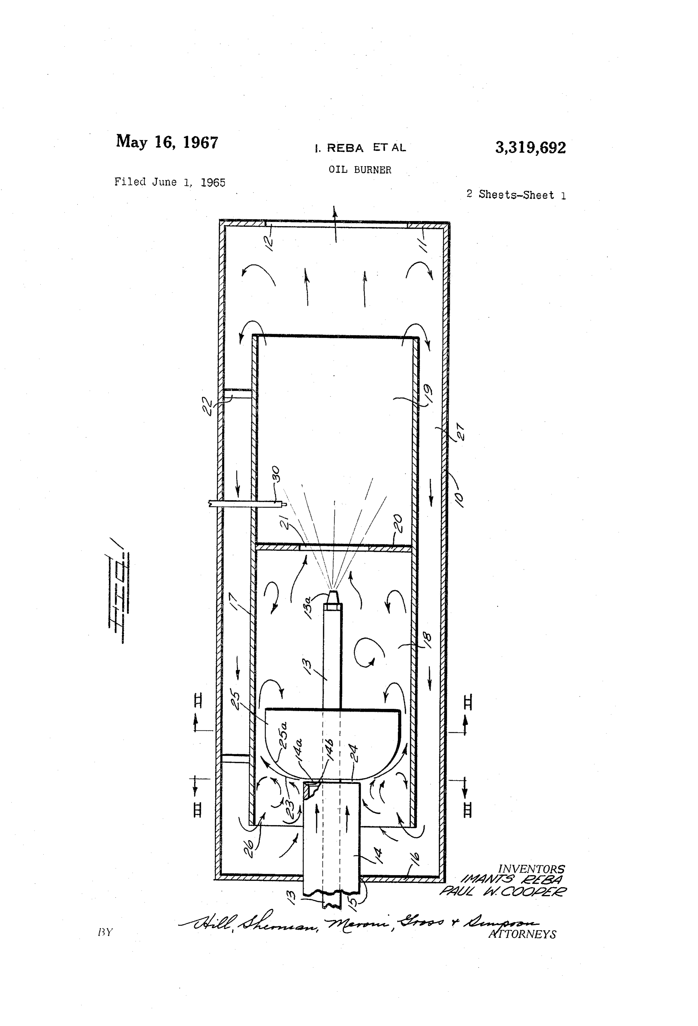
Still other further objects and features of the pres will at once become apparent to those skilled degree of cleanliness, in the presence of a blue or non in the art from a consideration of the attached sheets of luminous flame. This has been achieved without in any drawings way sacrificing over-all safety of the burner, since oper shown by wherein way of one embodiment of the invention is illustration only, and wherein:
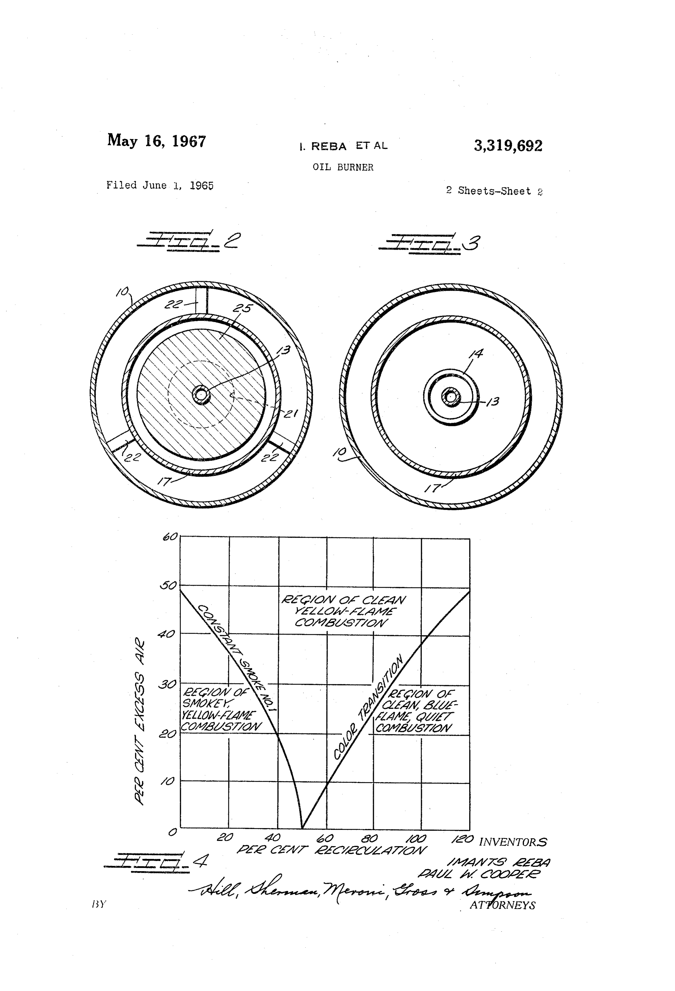
ation is intended to be, and is readily accomplished, in a FIGURE 1 is a generally cross-sectional view, in sche condition of excess combustion air so that carbon monox matic form, of a burner constructed in accordance with ide (CO) is eliminated from the combustion gases. the provisions of the present invention; In accordance with the present invention, the products FIGURE 2 is a cross-sectional view taken along the of combustion are recirculated in large proportion in the line II—III of FIGURE 1;
burner System. By providing a novel primary air flow system and simple vaneless, air flow control device, a very lineFIGURE 3 is a cross-sectional view taken along the III—III of FIGURE 1; and high rate of recirculation of the products of combustion FIGURE 4 is a chart illustrating certain fuel-air rela iscondition.
achieved with a highly efficient blue-flame burning tionships discovered to be important in the successful In accordance with the present invention, extremely propagation of a blue-flame oil burner. simple structural components are employed. The burner As shown on the drawings: We have discovered comprises a generally cylindrical outer housing open at mentation, including operation as a result of extensive experi the downstream end to provide flue gas exhaust. Air and of full-size oil burner con oil are introduced at the upstream end and a cylindrical figurations, that oil may be burned with sufficient effi intermediate diameter body is positioned within the ciency to provide a blue-fame in the presence of excess air. A preferred embodiment of our construction may outer cylindrical housing providing an annular recircula 60 be seen from a consideration of FIGURES 1 through 3 tion path about its outer peripheral surface and a com bustion Zone within its internally facing surface. Air is where our improved burner is shown in a somewhat schematic form.
introduced axially into the housing but is radially ejected As may be seen from FIGURES 1 through 3, the burn upstream of and immediately adjacent to a flow directing er of the present invention comprises an outer housing body comprising, preferably, a solid of revolution from generally indicated at 10, constructed in a generally providing a Surface generally curved, or relieved in the cylindrical form. Closing off the downstream end of the downstream direction. This surface causes a radially out main housing it), is an end plate it having an exhaust wardly directed stream of air to deflect toward and adja aperture 2 therein.
cent to the solid body under the phenomenon generally high pressure by way ofOila conduit is introduced under relatively 13 leading to a conven known as the Coanda effect. As a result of the phenome 70 tional high pressure atomizing nozzle 13a. Primary air non, no upstream air flow deflecting vanes are required. for combustion purposes is introduced into the cylindrical Instead, as a result of the simple configuration, air flows housing 10 by Way of a generally cylindrical conduit 14 4 which enters the housing 10 by way of an opening 15 ent flame characteristics. As may be seen, at levels of in the upstream closure wall 16. Primary air under a burner operation providing greater than 50% recircula relatively low fan induced pressure of two inches of tion of combustion products and moderate amounts of water has been found satisfactory and may be supplied excess air, the flame propagated is clean, blue or non from any conventional low pressure fan or blower, not 5 luminous, and quiet. It is extremely desirable to provide illustrated. for such a clean, blue-flame and, accordingly, apparatus Within the central area of the housing 10 a generally capable of satisfying these requirements at reasonable cylindrical shroud 17 is rigidly secured. The shroud cost provides a major contribution in the burner field. 17 is divided into two generally cylindrical chambers, The burner illustrated in applicants' FIGURES 1 through indicated at 18 and 19 and comprising, respectively, a IO 3 fully satisfies these requirements both as to burning mixing chamber and a combustion chamber separated by characteristics and as to expense. a separation plate 20 having a separation orifice 21 there In further considering the chart, FIGURE 4, it will in. The shroud 17 may be fixedly positioned within the be observed that percent recirculation identified by outer chamber 10 by any conventional means, such as standard c.f.m. of recirculated for example a plurality of generally radial spider ele combustion products X 100 ments 22 providing a recirculation passageway 27. Air R standard c.f.m. of stoichiometric air entering the housing by way of conduit 14 is radially directed outwardly in the direction indicated by the arrows The stoichiometric condition, in which no excess air 23, leaving an annular slit 24 formed by the upstream is present, can theoretically produce a clean blue-flame. surface of a body 25 having a curved surface of revolu 20 Although such stoichiometric combustion would be high tion 25a, and the downstream or trailing edge 14a of ly desirable from the standpoint of maintaining high unit the inlet conduit 14. The body 25 is rigidly Secured in efficiency, it is considered important to provide excess place within the mixing zone 18 by any convenient con air under substantially all furnace operation conditions to struction. For example, in the embodiment illustrated, reduce the dangers of carbon monoxide. Accordingly, the solid of revolution 25 is rigidly mounted directly on, 25 it is preferred that the system be operated at conditions and to, the fuel oil inlet conduit 13. It will be under of excess air. For example, it has been found through stood, however, that the body of revolution 25 may be operation of a burner constructed in accordance with the supported within the mixing zone by securing it directly present invention, and in the form illustrated in the draw to the shroud 17 by a spider, in the same manner as ings hereof, operation at approximately 15% excess air indicated at 22 with respect to the shroud 17. 30 with an inlet air pressure of 2.7 inches of water and As shown, air entering the mixing zone by way of the R=75%, no carbon monoxide appeared at the exhaust conduit 14 passes through slit 24 radially outwardly in and the burner was operating at a substantially smokeless the direction of the arrow 23. The presence of the curved condition with an essentially blue-flame. These results upstream surface of the solid of revolution 25 causes, were achieved employing a firing rate of 95 gallon per as a result of the known Coanda effect, an attachment of hour of No. 2 Distillate Fuel Oil with a nozzle tempera the air stream to the surface 25a with the resultant flow ture of 300' F. and a temperature in the annular flow of the air outwardly along the surface 25a and down recycle path 27 of approximately 1000 F. Further, at stream to the mixing zone. It has been found as a result stoichiometric conditions and with a blue-flame only 10 of our experimentation that this tendency of the air to to 20 p.p.m. CO was present. These characteristics co ward attachment to the surface 25a causes a pumping 40 incided with the expectations indicated from the chart action or entrainment of air or other gaseous material of FIGURE 4 and were accomplished with a burner con located in the area 26 immediately upstream of the structed in accordance with the structure of FIGURES curved body 25. In fact, the entrainment provides an 1 through 3 and having the following dimensions: efficient pump for causing forced draft recirculation of products of combustion by way of the passageway 27. 45 Length of housing 10-------- 24'.
This entrainment is improved significantly by providing Length of shroud 17--------. 18'. a sharp edge 14a on conduit 4 in the manner shown Spacing between shroud at 14b. 17 and housing wall 16---- 2'. Due to the positioning of the separation plate 20 and Diameter of shroud--------- 6'.
the mixing of primary air with the atomized fuel imme 50 Diameter of housing-------- 8'.
diately upstream of the separation plate 20, ignition of Diameter of air inlet the combustible mixture may satisfactorily be accom conduit 14-------------- 2'. plished by an electrode 30 positioned in the combustion Diameter of flow body 25---. 5', with curvature of sur chamber 19 or immediately upstream of the ignition ori face 25a comprising fice 21. This provides for the burning process in cham 55 1/2' radius fillet. ber 19, and, as will be more fully set forth below, the Axial dimension of combustion chamber length is preferably sufficiently slit 24------------------ great to provide complete combustion of the fuel prior Oil pipe 13---------------- to movement of the combustion gases downstream and 60 NOZZle 13d---------------- .75 gallon per hour, 60° out of the combustion chamber. As a result of this re solid spray nozzle spaced lationship combustion gases, that are recirculated up 1/8 ' upstream of sep stream by way of the annular passageway 27 back into aration plate 20. the shroud at area 26 for entrainment with the primary Separation orifice 21———————— 2% ' diameter. air passing about the flow body 25, are substantially com Exhaust opening 12--------- 534' diameter. pletely burned prior to movement through passage 27 Length of shroud downstream and addition to the primary air. It has been found that of separation wall 21------ 11'. for the purposes of providing a blue or nonluminous flame condition, substantially complete combustion of the recir During the experimental work, it became apparent culated gases is desirable. that variations may be made in the shape of the body Operation of the system hereinabove broadly disclosed 25 and the surface 25a thereof, with some effect on en is based upon discovered relationships relative to the trainment efficiency. However, that addition of axial recirculation of combustion gases. As may be clearly extension of the flow body after it attains its maximum seen from a consideration of the chart, FIGURE 4, vari diameter made no signifiacnt difference in operation. ous conditions of excess air and percentage of recircu Variations in various of the components will affect oper lation of combustion products provide significantly differ ation of the system somewhat and the preferred embodi 5 ments of the invention will conform generally to the shroud is constructed of sufficient length to encompass system equation: substantially complete combustion whereby recirculated gases are essentially completely burned prior to their re circulation. A factor of importance in design considera 5 tion, which was determined experimentally, is the fact in which the first term defines the geometry of the sys that the shroud should, for excellent performance, extend tem, the second term contains the flow parameters and at least one inch upstream of the inlet air slit 24. A the terms at the right of the equality sign relate to the lesser dimension provides incomplete entrainment while entrainment ratio. In the formula the terms are defined greater length of shroud upstream of the flow body pro as follows:
10 duces substantially no improvement of entrainment. The
Aa=area of inlet air slit, square inches utilization of a dimension of 1/3' for this factor has Ad=annular area at exit plane of flow body 25, square proved very satisfactory in operation. inches It will be apparent from the discussion above, that it S=inlet in slit width, inches is extremely important, in the propagation of a blue or r= radius of inlet air slit nonluminous flame, in connection with low pressure pri r= radius of flow body 25, inches mary air combined with household fuel oil to provide r= radius high percentages of recirculated products of combustion. sp(r) = radius of curvature of flow surface 25a as a func It has been found that the vaneless entrainment estab tion of radius of flow body 25, inches lished by the structure herein illustrated provides a com pletely satisfactory burner capable of successfully em g=conversion factor, 32.2 foot-lbs, mass/lbs.-force sec.2
APo=pumping pressure of attached jet system, inches of ploying low pressure primary air available from inexpen Water Sive home-use type blowers, conventional household fuel V=velocity through slit 24, feet per second oil, and extremely inexpensive construction to provide blue-flame operation. It will be clear to those skilled in
E_entrainment ratio, standard c.fm. entrained gas 25 the art that the recirculation of combustion gases may rw standard c.f.m. primary air be accomplished in manners different from that shown Ae=annular area between shroud and inlet air tube 14, in the embodiment illustrated herein. It is, accordingly, square inches. our intention that the present invention be limited solely to that scope set forth in the appended claims.
It has been found from experimentation that a burner 30 We claim as our invention:
constructed in accordance with the form illustrated in i. In combination in a fuel burner, a generally cylin the drawings fully satisfies successful operation under the drical housing, a generally cylindrical shroud fixedly se formula and provides a very high percent of recircula cured within said housing providing an axially extend tion, necessary to the provision of a blue or non-luminous ing passage between said housing and said shroud, an flame. At the same time, it has been found that opera 35 axially extending open-ended tubular conduit introducing tion of the burner is successful at very low primary air primary air under positive pressure axially into one end inlet pressures. These pressures may be on the order of said cylindrical shroud, means closing said one end of 2 inches of H2O which, when compared with the much of said housing around said conduit, a flow directing body higher air pressures employed in commercial burner in in said shroud intermediate the ends thereof and imme stallations, clearly piaces the burner of the present inven 40 diately downstream of the open end of said conduit and tion in the category of the inexpensive home oil burner combining there with to provide an annular radially open type of apparatus. Accordingly, we have found that cal ing slit for the passage of air from the conduit in a di culation of a burner in accordance with the formulae rection radially outwardly adjacent said body, means pro above set forth, permits utilization of an extremely inex viding an opening between the interior of said shroud and pensive design at a cost sufficiently low to permit its 45 Said passage upstream of Said body, the upstream sur widespread use in ordinary residential operation. Of face of said body being gradually curved in the down course, design considerations suggest that a relatively sim stream direction whereby air leaving said slit attaches to ple construction be employed if possible. Toward this said surface for deflection downstream in said shroud and end, the design of a specific installation for any given for entrainment of gas in said shroud upstream of the need suggests that a number of the factors in the for 50 body, means introducing fuel into said shroud down mula be considered as predetermined by the economics stream of said body for mixture with air flowing down of commercial manufacture. Thus, in designing a burner Stream around said body, means for igniting said mix along the lines of the burner illustrated in the drawings ture in said shroud to provide combustion at the down of the present application, certain areas may be predeter stream end of said shroud and an opening in the down mined from presently accepted practice. Thus, by using 55 stream end of said housing providing for the escape of the chart, FIGURE 4, and employing a fixed predeter exhaust gases following combustion. mined firing rate for the fuel, a fixed air flow rate to pro 2. In combination in a fuel burner, a generally cylin vide the percent excess air, the amount of inlet air is drical housing, a generally cylindrical shroud fixedly se calculatable and the flow rate of the recirculated prod cured concentrically within said housing and spaced there ucts may readily be determined. The diameter of the 60 from providing an axially extending annular passage be separation orifice is chosen in accordance with present tween said housing and said shroud, an axially extend accepted practice for high pressure type oil burners, i.e., ing open-ended tubular conduit introducing primary air between 2.5 and 3.0' for operation in the range of one under positive pressure axially into one end of said cylin gallon per hour. The position of the nozzle upstream drical shroud, means closing said one end of said hous of the separation orifice is, similarly, determined by a ing around said conduit, a flow directing body in said conventional practice and as such, is on the order of shroud intermediate the ends thereof and immediately slightly over an inch from the separation orifice. The downstream of the open end of said conduit and combin shape of the flow body may be modified somewhat but ing with the open end of said conduit to provide an an choice of the generally circular solid of revolution pro nular radially opening slit for the passage of air from vides a simply calculatable form having very adequate 70 the conduit in a direction radially outwardly adjacent performance. The diameter of the flow body and the said body, means providing an opening between the in diameter of the shroud is readily computed by equating terior of said shroud and said passage upstream of said the sum of the recirculation and inlet air flow rates, com body, the upstream surface of said body being gradually bined to the estimated flame velocity such that the flame curved in the downstream direction whereby air leaving is stabilized within the shroud. As above noted, the said slit attaches to said surface for deflection downstream
Page 6drawing sheetscan →
Page 7scan →
said shroud and said passage at a point upstream of said conduit to provide an annular radially open slit for the body, the upstream surface of said body being gradually curved in a downstream direction whereby air leaving outwardly adjacent said body, saidinshroud passage of air from said conduit a direction radially being axially said slit attaches to said surface for deflection downstream spaced from said means closing said one end of said in said shroud and for entrainment of gas in said shroud housing to provide an opening between the interior of upstream of the body, an annular separating plate provid said shroud and said passage at a point upstream of said ing a separation orifice intermediate the ends of said body and providing an extension of said shroud a dis shroud dividing the shroud into a mixing chamber up tance in excess of one inch upstream of said slit, the up stream of a combustion chamber, means introducing stream surface of said body being gradually curved in a atomized liquid fuel into said shroud downstream of said 0 downstream direction whereby air leaving said slit at body and upstream of said plate for mixture with air taches to said surface for deflection downstream in said flowing downstream around said body, means for igniting shroud and for entrainment of gas in said shroud up said mixture and said shroud to provide combustion in stream of the body, means introducing atomized liquid said combustion chamber, and an opening in the down fuel into said shroud downstream of said body, for mix stream end of said housing at a point beyond the down 5 stream end of said annular passage providing for the ture with air flowing around said body, means igniting said mixture, and an opening in the downstream end of escape of exhaust gases following combustion while per the housing at a point beyond the downstream end of said mitting recirculation of part of the products of combus annular passage providing for the escape of exhaust gases tion via said annular passage. following combustion while permitting recirculation of 8. In combination in a fuel burner providing blue 20 part of the products of combustion via said annular flame operation, a generally cylindrical housing, a gen passage.
erally cylindrical shroud fixedly secured concentrically References Cited by the Examiner within said housing and spaced therefrom providing an UNITED STATES PATENTS axially extending annular passage between said housing and said shroud, an axially extending open-ended tubular 2,056,531. 10/1936 Morton -------------- 158-1 conduit introducing primary air under positive pressure 2,701,608 2/1955 Johnson ------------- 158-1 axially into one end of said cylindrical shroud, means 2,918,117 12/1959 Griffin ?----?-?------------- 158-1 closing said one end of said housing around said conduit, 3,174,526 3/1965 Von Linde –––------- 158-1 X a flow directing body in said shroud intermediate the ends thereof and immediately downstream of the open end of 30 FREDERICK. L. MATTESON, JR., Primary Examiner. said conduit and combining with the open end of said E. G. FAVORS, Assistant Examiner.
Provenance
- Collection
- Patents citing this work
- Pages
- 7
- Method
- pdftotext (the PDF's own text layer) + pdftoppm 300dpi page scans
- Patent office record
- patents.google.com →
- Source
- Google Patents citing-documents table
- Assignee
- Iit Res Inst
- Published
- 1967-05-16
- Transcribed from
- patentimages.storage.googleapis.com →