

patent · US4448232A
Bi-fold door assembly
15 May 1984
Text
Page 1bibliographic recordscan →
United States Patent (19)
McQueen et al.
(54) BI-FOLD DOOR ASSEMBLY
75 Inventors: Coy E. McQueen; Lynn O. Twedt, both of Harvard, Ill.
(73) Assignee. Erect-A-Tube, Inc., Harvard, Ill.
Int. Cl............................................... E05D 15/26 52 U.S. C. ..................................... 160/207; 136/291
3,155,147 11/1964 Smith ....... ... 16/207 x 3,648,755 3/1972 Thiele....... ... 60/201 4,026,267 5/1977 Coleman ............................. 126/436
4,261,409 4/1981 De Vore ............................. 160/207 Primary Examiner-Peter M. Caun
Assistant Examiner-Cherney S. Lieberman
Attorney, Agent, or Firm-Arnstein, Gluck, Lehr,
A bi-fold door assembly for a building. The door assem bly includes an upper door section and a lower door section hinged to one another together with a door track mounted in an upwardly and inwardly inclined position. Additionally, the bottom of the lower door section cooperates with the door track for guided rais ing and lowering movement of the bi-fold door. The door assembly may also include an automatic opener operatively associated with the upper and lower door sections. When provided, the automatic opener may include a battery powered electrical motor together with a battery operatively associated with a solar panel for recharging thereof.
12 Claims, 10 Drawing Figures
Drawings
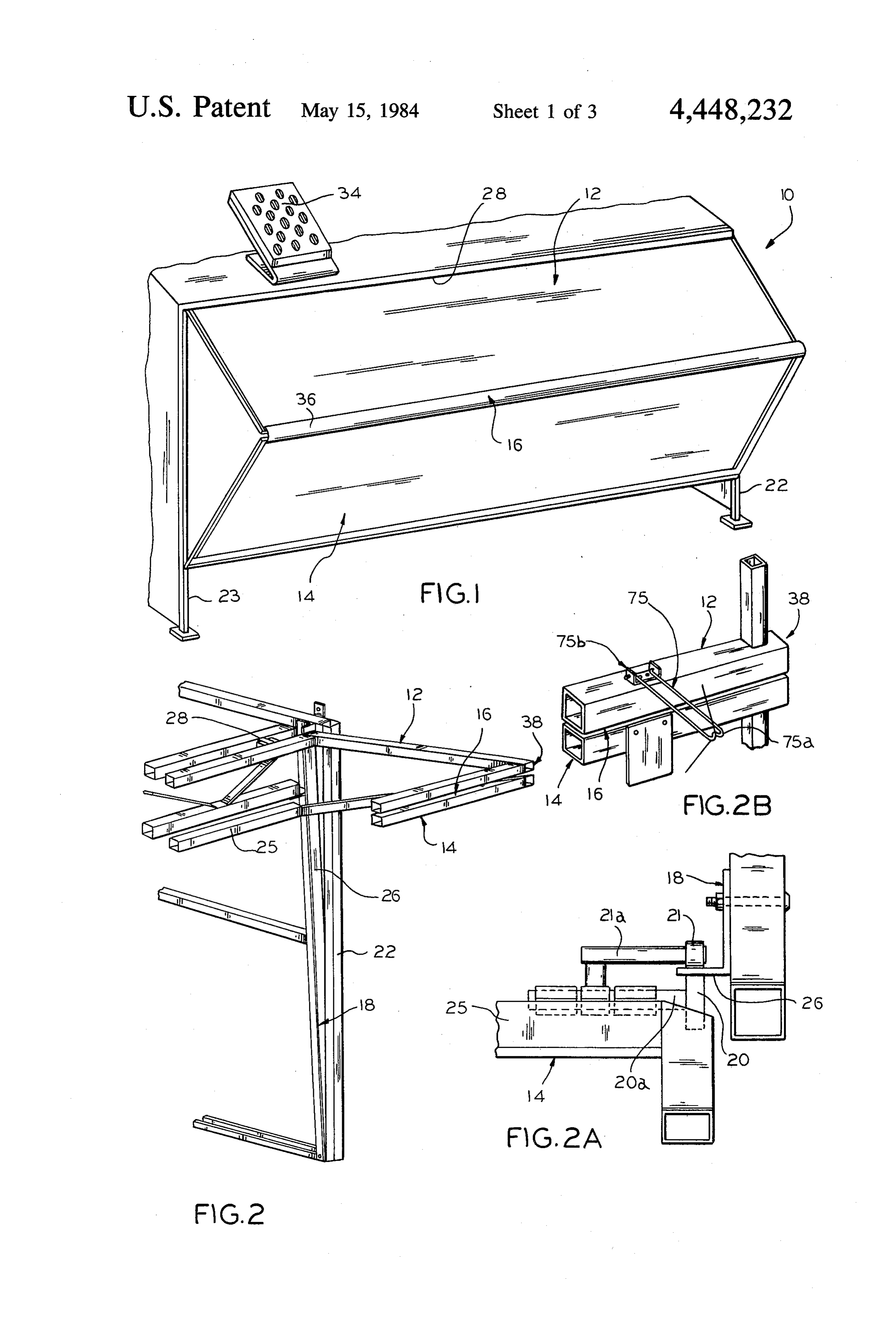
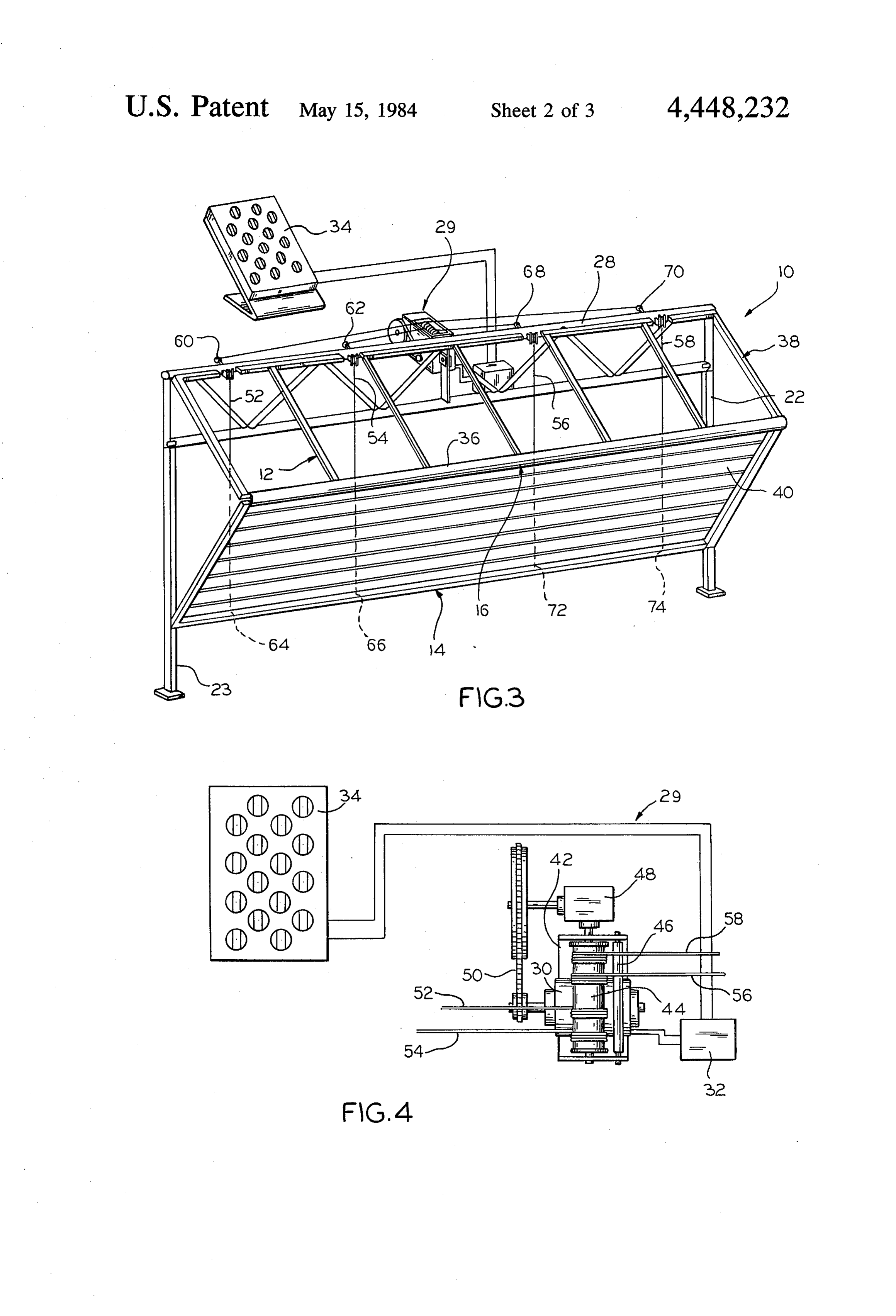
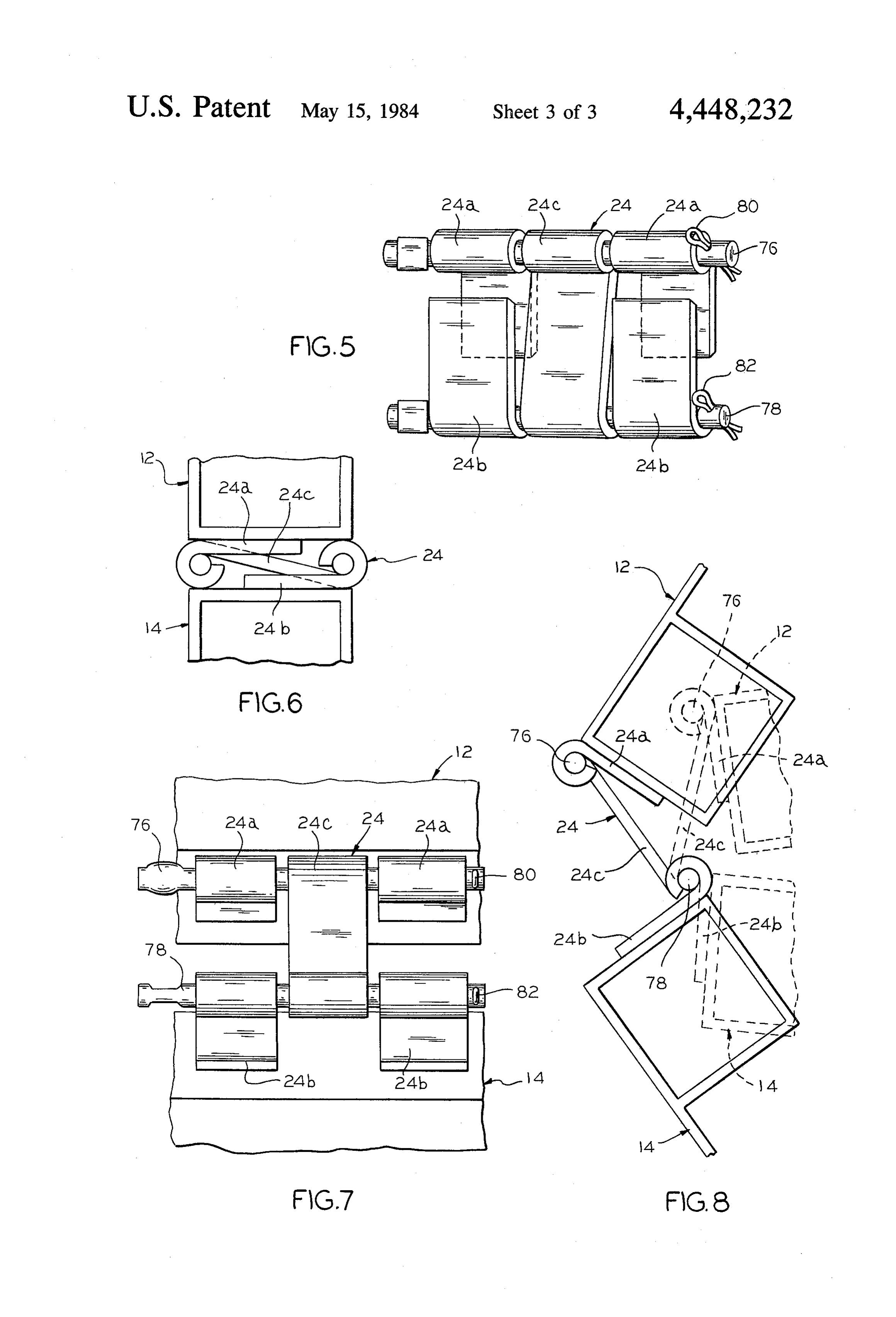
FIG. 3 is a perspective view similar to FIG. 1, with Still referring to FIGS. 2 and 2A, the door track 18 portions removed, for clarity in illustrating the inven includes straight sections each of which is associated tion;
FIG. 4 is a plan view of an automatic opener assem tions 12 and 14.ends with opposing
Page 2drawing sheetscan →
Page 3drawing sheetscan →
Page 4drawing sheetscan →
Page 5scan →
B-fold door assembly
following description when considered in connection with the accompanying drawings.
Background of the invention summary of the invention
The present invention relates to doors and, more In general, the objects and advantages of the present particularly, to an improved bi-fold door assembly. invention are met by providing a bi-fold door assembly In recent years, the use of out buildings for storage for a building having a unique combination of features has expanded to a very significant degree. Such build and components. The assembly includes an upper door section and a lower door section hinged to one another ings have found use, for instance, as hangers to accom 10 together modate the considerable expansion in the use of small inwardlywith a door track mounted in an upwardly and aircraft for both business and pleasure with the resulting upper andinclined lower position. Witn this construction, the door sections are disposed in a com problem of providing adequate shelter at a reasonable price and for storage of large equipment such as farm mon plane when the door is fully lowered, the common plane being inclined upwardly and inwardly to lie in a machinery, earth moving equipment, large trucks and 15 plane defined by the door track. The assembly also the like. As a result, the need for large doors for such includes means associated with the bottom of the lower buildings which operate safely, effectively and effi door section cooperating with the door track for guided ciently has been the focus of those in this field. movement of the door. With these features of construc Some years ago, Erect-A-Tube, Inc., our assignee, pioneered the development of a unique bi-fold door. 20 tion, the weight of the door serves to assure that the door fully closes.
These doors, which are quite large in size ranging to at More specifically, the upwardly and inwardly in least 80 feet wide by 20 feet high, have become a stan clined orientation of the door track provides a particu dard. It is now recognized that the bi-fold door gives larly advantageous result with the bi-fold door. The rugged, dependable service and is reliable and easy door, whether fully opened, fully lowered, or at some working even in ice and snow. These doors, which are 25 intermediate position, has a horizontal force component easy to install on post-frame or steel buildings, can be caused by the weight of the door which serves to stabi sheeted and insulated with conventional building mate lize the door in any position while assuring that the door rials. As such, the bi-fold doors give extra clearance for completely closes and remains in a closed position when large openings and are compatible with all metal build fully lowered. Because of this feature, the bi-fold door ing systems. 30 assembly has virtually no tendency to bind during oper In the past, bi-fold doors have been adapted to coop ation, to stick in a partially opened position when fully erate with vertical door tracks. The door, which in lowered, or to flutter when fully lowered during gusty cludes two parallel door sections which are horizon wind conditions.
tally hinged, includes means on the bottom of the lower Another unique feature of the present invention is the door portions to cooperate with the vertical door track. 35 utilization of a bi-fold door assembly having an auto As a result, the bottom of the door moves straight up matic opener operatively associated with the upper and from the floor so that snow and ice cannot restrict the lower door sections. The automatic opener includes a opening action in any way thereby reducing the need battery powered electrical motor and a battery which is for snow removal while eliminating frozen door prob operatively associated with a solar panel for recharging lems. thereof. With this feature of construction, the bi-fold Despite the numerous significant advantages to a door assembly is well suited for use in remote regions bi-fold door, several problems have remained unre having no supply of electricity.
solved. The principal problem has been the difficulty in In a preferred embodiment, the upper and lower door assuring that the door fully closes when it is lowered so 45 sections are hinged to one another by means of a double as to provide the requisite security and to fully protect acting hinge to provide free relative movement of the the contents of the building from weather conditions. erably upper and lower sections. The assembly then also pref. Because of the vertical door tracks, and the uniqueness the lower includes means for limiting pivotal movement of of the configuration of the door, the bi-fold door can door section to a single side of the plane have a tendency to stick in a partially opened condition. 50 defined by the upper door section where the limiting means comprises a bearing surface on the door track
Another problem with bi-fold doors has been the adapted to support the upper and lower door sections difficulty in supplying electrical power for automatic when fully lowered in the upwardly and inwardly in openers. This is particularly true for applications such as aircraft hangars located in remote regions or other clined common plane previously described. The door track may be formed of steel angles having outwardly buildings provided for the storage of construction 55 facing surfaces comprising bearing surfaces and defin equipment or other large equipment in areas where ing straight there is limited access and difficulty in supplying electri the upper andsections lower associated with opposing ends of door sections.
cal power. Accordingly, since bi-fold doors are by na Additionally, the top of the upper door section is ture quite heavy, it has been difficult to utilize their preferably hinged for pivotal many advantages in buildings located in remote regions. cent the top of the door track. movement closely adja It is therefore an object of the present invention to is then adapted for pivotal movement in a door The upper section single direc provide a bi-fold door assembly which takes full advan tion opposite the direction of pivotal movement of the tage of the many features inherent in prior bi-fold door constructions while overcoming the few remaining lower door section. More specifically, the top of the upper door section and bottom of the lower door sec obstacles to perfecting the design, construction and 65 tion always remain in a plane defined by the door track. operation of such doors. The lower door section includes guide rollers and col These and other objects, features and advantages of umn followers mounted on opposite ends at the bottom the present invention will become apparent from the thereof for movement along the door tracks, With this 6 arrangement, the upper and lower door sections are the opening in the building. Also as suggested in FIG.2, moveable between positions in which they lie in a com the upper and lower door sections 12 and 14 are dis mon plane when fully closed and lie in a canopy posi posed in a canopy position when fully opened. tion when fully opened. Referring to FIGS. 5 through 8, it will seen that the With these features of construction, the bi-fold door upper and lower door sections 12 and 14 are hinged to assembly of the present invention accomplishes the one another by means of a double acting hinge 24. The objects defined hereinabove. double acting hinge 24 permits the lower door section BRIEF DESCRIPTION OF THE DRAWINGS 14 to pivot to either side of a plane defined by the upper In the drawings: door section 12, i.e., the upper and lower door sections O 12 and 14, when so hinged without stops or other move
FIG. 1 is perspective view of a bi-fold door assembly ment limiting structure, are free to pivot relative to one for a building in accordance with the present invention; another throughout substantially 360 degrees. How FIG. 2 is a perspective view of a portion of the frame ever, as will be appreciated, the bi-fold door assembly with the sheeting removed and the frame in a fully 15 10 includes means for limiting pivotal movement of the opened position taken along the right hand side of the lower door section 14 to a single side of the plane de bi-fold door assembly of FIG. 1; fined by the upper door section 12. FIG. 2A is an enlarged top plan view, in detail, illus Referring now to FIGS. 2 and 2A, the limiting means trating a guide roller and column follower taken along includes a bearing surface 26 on the door track 18. It the right hand side of the lower most portion of the will be appreciated that the bearing surface 26 is pro vided on each of the door track sections 18 and that it
FIG. 2B is an enlarged perspective view, in detail, faces outwardly in confronting relationship to support illustrating a device for initiating the opening move the upper and lower door sections 12 and 14 when fully ment of the door with the frame in a fully closed posi lowered. Moreover, as can be seen, the door track 18 is tion taken along the right hand side of the bi-fold door formed of steel angle with the outwardly facing surface comprising the bearing surface 26.
FIG. 3 is a perspective view similar to FIG. 1, with Still referring to FIGS. 2 and 2A, the door track 18 portions removed, for clarity in illustrating the inven includes straight sections each of which is associated tion;
FIG. 4 is a plan view of an automatic opener assem tions 12 and 14.ends with opposing
The of the upper and lower door sec top of the upper door section 12 is bly adapted for use with the bi-fold door assembly; and then preferably hinged
FIG. 5 through 8 are different views illustrating the the top of the door trackfor 18 pivotal movement adjacent as at 28 in a single direction construction and operation of a hinge in accordance opposite the direction of pivotal movement of the lower with the present invention.
door section 14. With guide rollers 20 and column foll
DETALED DESCRIPTION OF THE 35 lowers 21 engaged with the door track 18, the top of the PREFERRED EMBOEDIMENTS upper door section 12 and the bottom of the lower door Referring to the drawings, and first to FIG. 1, the section 14 always remain in a plane substantially defined reference numeral 10 designated generally a bi-fold by the door track 18.
door assembly for a building in accordance with teh As will be appreciated, the guide rollers 20 and the present invention. The bi-fold door assembly 10 in- 40 column followers 21 are engaged with the door track 18 cludes an upper door section 12 and a lower door sec for movement therealong, which can be accomplished tion 14, the door sections having front surfaces facing in the fashion illustrated, by utilizing pins 20a and arms outwardly of the building and rear surfaces facing in 21a joined to the horizontal frame member 25. wardly thereof, the upper door section 12 and the lower Morover, as previously mentioned, the guide rollers 20 door section 14 being hinged to one another as at 16 (see 45 and column followers 21 will be mounted on opposite also FIG. 6). A door track 18 which is suitably an angle sides at the bottom of the lower door section 14 to iron bolted to the frame of the building, is also provided accommodate the desired movement of the bi-fold door and is mounted adjacent the inwardly facing rear sur assembly 10 and between a fully lowered and a fully faces of the door sections in an upwardly and rear raised position.
wardly, i.e., inwardly, inclined position relative to the SO As will also be appreciated, the guide rollers 20 and building (see FIGS. 2 and 2A). The bi-fold door assem the column followers 21 are mounted on opposite sides bly further includes means such as a guide roller 20 and at the bottom of the lower door section 14 in a manner column follower 21 associated with the bottom of the accommodating one of the unique features of the pres lower door section 14 cooperating with the door track ent invention. Specifically, they are mounted such that 18 (see particularly FIG. 2A). With these features of 55 the upper and lower door sections 12 and 14 rest against construction, the bi-fold door assembly 10 overcomes the bearing surfaces 26 on each of the straight sections the problems and accomplishes the objectives set forth at opposite ends of the door comprising the door track in detail hereinabove. 18 when the door is fully lowered. As shown in detail in As will be appreciated, the upper and lower door FIG. 2A, it will be appreciated that this is accomplished sections 12 and 14 are disposed in a common plane 60 by locating the guide rollers 20 in the proper position when fully lowered. It will be seen by referring to the relative to the inside of the lower door section 14. vertical frame members 22 and 23 in FIGS. 1 and 2 that With this arrangement, the upper and lower door the common plane defined by the fully lowered door sections 12 and 14 are sized to lie against the door track sections 12 and 14 is slightly inclined upwardly and 18. Since the straight sections comprising door track 18 rearwardly to the plane defined by the frame members, 65 are inclined upwardly and rearwardly, the weight of the i.e., inwardly relative to the building, the fully lowered upper and lower door track sections 12 and 14 include door sections 12 and 14 lying in a plane defined by the a large force component directed along the door track two door track sections (such as 18) on opposite sides of 18 (generally vertical) and also includes a smaller force 7 component extending generally perpendicular to the bers such as the vertical frame member 22, gives the plane defined by the door track 18 (generally horizon structural integrity required of a door of substantial size tal). By reason of these force components, the bi-fold and also is relatively easy to manufacture, ship and door assembly 10 successfully achieves the objective of install at a relatively low cost while giving long years of assuring that the upper and lower door sections 12 and effective use with a minimum of problems. While this 14 operate in the intended fashion at all times. construction has been illustrated, it will be appreciated In particular, the generally vertical force component that the features and advantages inherent in the bi-fold serves to assure that the upper and lower door sections door assembly of the present invention are applicable 12 and 14 can be fully lowered at desired times. It will and usable with other constructions as well. then be appreciated that the generally horizontal force 10 Referring to FIG. 4, the automatic opener 29 includes component assures that the upper and lower door sec a support plate 42 upon which the electrical motor 30 is tions 12 and 14 will remain in contact with the bearing mounted. The support plate 42 also carries a take-up surfaces 26 on each of the straight sections comprising roller 44, a guide roller 46, and a gear box 48. With this the door track 18 thereby assuring that the upper and arrangement, the electrical motor 30 drives the take-up lower door sections 12 and 14 will remain in fully low 15 roller 44 through a shaft and pulley mechanically se ered position until such time as it is desired to raise the cured to the motor which drives a drive belt 50 which, door. In contrast to vertical hanging of doors, the gen in turn, drives a shaft and pulley mechanically secured erally horizontal force component serves to counteract to the gearbox 48 which, in turn, drive the take-up roller any tendency of the bi-fold door assembly 10 to par 44 through another shaft, in conventional fashion. tially open in gusty wind conditions and the like. 20 As shown in FIGS. 3 and 4, a plurality of lift cables Referring to FIG. 2, the magnitude of the force com 52, 54, 56 and 58 are utilized. The lift cables 52 and 54 ponents can easily be varied as desired. It will be appre pass under the take-up roller 44, through pulley guide ciated that this can be accomplished by varying the assemblies 60 and 62, and are attached at the bottom of angle the door track 18 (and thus the upper and lower the lower door section 14 as at 64 and 66 and the lift door sections 12 and 14 in a fully lowered position) 25 cables 56 and 58 pass over the take-up roller 44 and the make with the vertical as presented by the vertical guide roller 46, through the pulley guide assemblies 68 frame member 22. By increasing the angle, the generally and 70, and are attached at the bottom of the lower door horizontal force component can be increased although section 14 as at 72 and 74. With this arrangement, the with a commensurate decrease in the generally vertical automatic opener 28 can easily and effectively raise and force component. 30 lower the bi-fold door assembly 10. Referring now to FIG. 3, the upper and lower door As shown in FIG. 2B, it is advantageous to provide sections 12 and 14 can advantageously be raised and the bi-fold door assembly with a device for initiating the lowered by means of an automatic opener 29. The auto opening movement of the door This device 75, which matic opener 29, particularly in remote regions, can be may conveniently be referred to as a "door popper", electrically operated by means of an electrical motor 30 35 holds one of the lift cables (such as 54 or 56) inwardly powered by a battery 32 (see FIG. 4). Because of the away from the tubular steel frame 38 so that as the door ease of operation of the bi-fold door assembly 10, the begins to open, the lift cable exerts not only a lifting battery powered electrical motor 30 is fully adequate force, but also a generally horizontally outward force and the battery 32 can be operatively associated with a substantially at the hinge point 16. As a result, the upper solar panel 34 for recharging thereof. and lower door sections 12 and 14 open outwardly (as While the applications for the bi-fold door assembly shown in FIGS. 1, 2 and 3) without any tendency to are wide ranging, one particularly advantageous appli bind.
cation is for use with aircraft hangars. The unique na Referring to FIG. 2B in some detail, the door popper ture of aircraft hangars are ideally suited for utilization 75 preferably includes a cable support 75a pivotally of the bi-fold door assembly of the present invention 45 secured to a mounting bracket 75b attached to one of which similarly accommodates the objective of provid the tubular support members of the frame 38. It will also ing a device well suited for use in remote regions or in be seen that a plate may be provided beneath the door regions where electrical supply is not readily available popper 75 in line with the cable being carried thereby, or in regions with severe climatic conditions that re and it will also be appreciated that it is highly advanta quire extra precautions against weather damage and the SO geous to provide a door popper for each cable utilized like to the contents of a building. However, as will be (such as 52, 54, 56 and 58), although it may be possible appreciated, the bi-fold door assembly of the present in certain instances to provide a door popper in associa invention can successfully be utilized with a multitude tion with a lesser number of cables than the total num of structures. ber actually being used for a particular bi-fold door Referring to FIG. 1, the joint where the upper and 55 assembly. With the construction illustrated in the draw lower door sections 12 and 14 are hinged to one another ings, a highly effective device for initiating the opening as at 16 is preferably covered with a flexible weather of a door has been provided.
stripping 36. This serves to render the bi-fold door as Referring to FIGS. 5 through 8, a double acting sembly 10 more weathertight and also serves to protect hinge 24 is illustrated in some detail, and includes inde the double acting hinge 24 from the weather which pendent leaves 24a and 24b and common leaf 24c, all of could possibly cause rusting and consequent difficult which are held together by means of hinge pins 76 and operation. Of course, the bi-fold door assembly 10 can 78 together with cotter keys 80 and 82. As shown, the further be provided with other weather stripping to leaves 24a are secured to the frame of the upper door render it more weathertight in conventional fashion. section 12 and the leaves 24b are secured to the frame of Referring to FIGS. 2 and 3, the upper and lower door 65 the lower door section 14, both of which may be se sections 12 and 14 are preferably constructed of a tubu cured to their respective frames by a common means lar steel frame 38 covered with a sheet material 40. This such as welding or the like. Also, while only a single type of construction, which includes structural mem double actinghinge 24 has been described herein, it will 8 be appreciated by those skilled in the art that, in prac 5. The bi-fold door assembly of claim 4 in which said tice, a plurality of such hinges will be used. limiting means includes said bearing surface on said Various changes coming within the spirit of the pres door track.
ent invention may suggest themselves to those skilled in 6. The bi-fold door assembly of claim 5 in which said the art. Hence, it will be understood that the invention door track is formed of steel angle, said steel angle including an outwardly facing surface, said outwardly is not to be limited to the specific embodiments shown facing and described or the uses mentioned. On the contrary, surface comprising said bearing surface. 7. The bi-fold door assembly of claim 6 in which said the specific embodiments and uses are intended to be door track includes straight sections associated with merely exemplary with the present invention being 10 opposing ends of said upper and lower door sections, limited only by the true spirit and scope of the appended said straight sections both being formed of steel angles claims. with outwardly facing surfaces. We claim: 8. The bi-fold door assembly of claim 7 in which the 1. A bi-fold door assembly for a building, comprising: top of said upper door section is adapted to be hinged an upper door section and a lower door section 15 door for pivotal movement above the top of said straight hinged to one another, said door sections having adaptedtrack section, said upper door section being front surfaces facing outwardly of said building posite thefordirection pivotal movement in a single direction op of pivotal movement of said lower and rear surfaces facing inwardly thereof; door section.
a door track mounted adjacent said inwardly facing 20 9. The bi-fold door assembly of claim 8 in which the rear surfaces of said upper and lower door sections top of said upper door section and the bottom of said in an upwardly and inwardly inclined position lower door section always remain in a plane defined by relative to said building; said straight door track sections, said upper and lower means associated with the bottom of said lower door door sections being disposed in a common plane when section cooperating with said door track; 25 fully closed. - said upper and lower door sections being disposed in 10. The bi-fold door assembly of claim 8 in which the a common plane when fully lowered; top of said upper door section and the bottom of said said common plane being inclined upwardly and in said lower door section always remain in a plane defined by wardly relative to said building to lie in a plane 30 beingdoor track, said upper and lower door sections disposed in a canopy position when fully opened.
defined by said door track; and 11. The bi-fold door assembly of claim 1 in which said a bearing surface on said door track adapted to sup means cooperating with said door track comprises a port said upper and lower door sections when fully guide roller and a column follower, said guide roller lowered. and said column follower engaging said door track for 2. The bi-fold door assembly of claim 1 in which said 35 movement therealong, said guide roller and said column upper and lower door sections are disposed in a canopy follower being mounted on the bottom of said lower position when fully opened. door section.
3. The bi-fold door assembly of claim 1 in which said 12. The bi-fold door assembly of claim 1 in which said upper and lower door sections are hinged to one an by upper and lower door sections are raised and lowered other by means of a double acting hinge. means of an automatic opener, said automatic opener being electrically operated by means of a battery pow 4. The bi-fold door assembly of claim 3 including ered electrical motor and a battery, said battery being means for limiting pivotal movement of said lower door operatively associated with a solar panel for recharging section to a single side of said plane defined by said thereof.
upper door section. 45 k k k k sk
Provenance
- Collection
- Patents citing this work
- Pages
- 8
- Method
- pdftotext (the PDF's own text layer) + pdftoppm 300dpi page scans
- Patent office record
- patents.google.com →
- Source
- Google Patents citing-documents table
- Assignee
- Erect-A-Tube, Inc.
- Published
- 1984-05-15
- Transcribed from
- patentimages.storage.googleapis.com →