

patent · US4545366A
Bi-focussed solar energy concentrator
8 October 1985
Text
Page 1bibliographic recordscan →
United States Patent (19)
BI-FOCUSSED SOLAR ENERGY
CONCENTRATOR
75 Inventor: Mark J. O'Neill, Richardson, Tex.
(73) Assignee: Entech, Inc., Tex.
51 Int. Cl." ................................................. F24J 3/02 U.S. Cl. .................................... 126/440; 136/246;
(58) Field of Search ....................... 126/440, 417, 452;
3,915,148 10/1975 Fletcher et al. ...... ... 126/440 X 3,991,741 1 1/1976 Northrup, Jr. et al ... 126/440 X 4,069,812 1/1978 O'Neill .................. ... 26/440 X 4,116,223 9/1978 Vasilantone .. 126/440X 4,299,20 1 1/1981 Tsubota ............................... 26/440
FOREIGN PATENT DOCUMENTS
Primary Examiner-Larry Jones
Attorney, Agent, or Firm-Harold E. Meier
A refractive optical concentrator for focussing solar energy on to small focal spots includes a linear Fresnel lens optically cross-coupled with simple cylindrical lenses. The cross-coupled lens concentrator comprises an optically clear dielectric material, such as acrylic plastic, with a plurality of linear prisms formed on its inner surface, and a plurality of perpendicularly mounted cylindrical lenses formed on its outer surface, such that the cylindrical lenses focus the sunlight toward a series of lateral axes and the prisms re-focus the sunlight along a longitudinal axis. The bi-focussed radiant energy is thereby concentrated upon a series of photovoltaic cells for transforming sunlight into electri cal energy.
18 Claims, 2 Drawing Figures
Drawings
Page 2drawing sheetscan →
Page 3scan →
plished and higher overall concentration ratios can be
B-FOCUSSED SOLAR ENERGY achieved than would be possible with conventional CONCENTRATOR linear Fresnel lenses.
Field of the invention brief description of the drawings
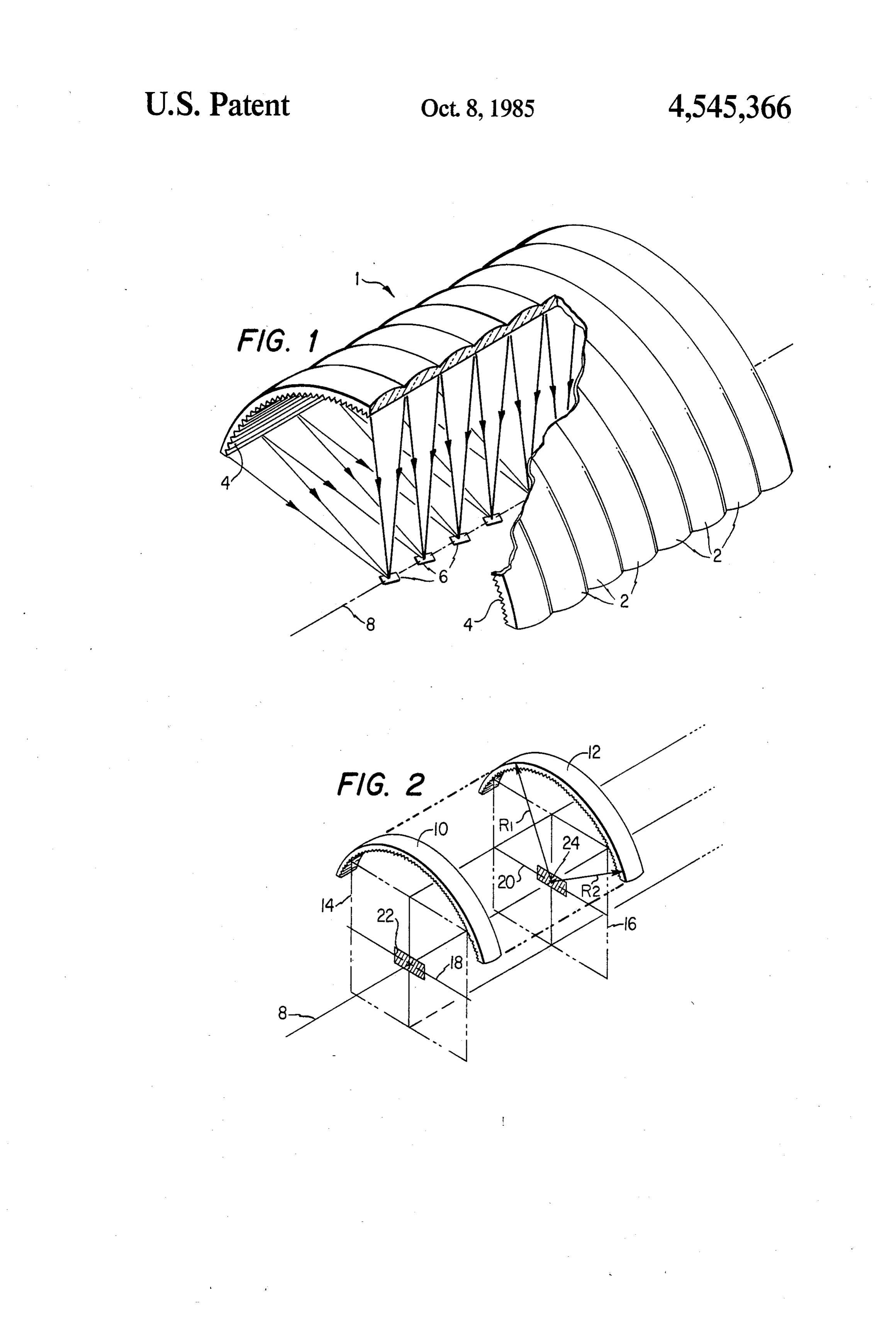
The present invention relates generally to solar en A better understanding of the present invention may ergy concentrators and more specifically to a concen be had from the following detailed description, when trating lens and solar energy concentrator for focussing read in connection with the accompanying drawings in incident radiant energy on to incremental focal spots on 10 which:
the surface of a receiver. FIG. 1 shows a perspective cut-away view of a pre
Background of the invention
ferred embodiment of the cross-coupled bi-focussing lens system of the present invention; and
Solar energy collection systems which utilize optical FIG. 2 illustrates certain operational aspects of the concentrators to focus incident sunlight on to small 15 lens system.
energy receivers offer many cost and performance ad DETAILED DESCRIPTION OF THE vantages over flat-plate solar energy collectors. In heat PREFERRED EMBODEMENT collector applications, the energy receiver area loses heat to the environment by radiation, convection and Referring to FIG. 1. in detail, there is shown a cross conduction. Accordingly, receivers with smaller re coupled lens structure 1 and photovoltaic elements 6. ceiver areas would have smaller heat losses and operate 20 The elements 6 are arranged to be electrically con more efficiently. In photovoltaic collector applications, nected together and the lens structure 1 is designed to such focussing collectors would also utilize much be placed within the aperture of a solar energy housing smaller quantities of expensive semiconductor materials such as shown in U.S. Pat. No. 4,069,812. The lens such as silicon, due to the smaller receiver area. One structure includes a series of cylindrical lens elements particularly effective solar concentrator is the linear 25 2 mounted adjacently to each other along the length of Fresnel lens system of U.S. Pat. No. 4,069,812. That the lens structure 1. The inner surface of the lens struc collector system has been developed to provide effi ture 1 is comprised of a plurality of linear prisms 4 cient collection of heat, photovoltaic electricity, and a mounted adjacently to each other in a direction perpen combination of both. However, due to the basic physics dicular to the axes of the cylindrical lenses 2 and run of linear Fresnel lens concentrators, the concentration 30 ning parallel ratio, which is defined as the lens aperture area divided collector. Thetocross-coupled the longitudinal receiver axis 8 of the by the illuminated receiver area, is practically limited to to focus incident energy uponlens structure 1 is arranged values between 25 and 50. It is highly desirable to pro voltaic cell elements 6. Without theofcylindrical a series discrete photo lens vide higher concentration ratios of 100 to 200. Higher concentration ratios would allow the same radiant en 35 elements 2, incident sunlight would be refracted by the ergy to be collected, for example, in a photovoltaic Fresnel lens prisms 4 and focussed along a longitudinal application, but would require significantly smaller axis 8 located at the focal axis of the fresnel lens as solar photovoltaic cells thereby substantially reducing shown in U.S. Pat. No. 4,069,812. While that construc the cost of the system. tion is very efficient, it requires a continuous photovol 40 taic surface along the axis 8 in order to maximize the
SUMMARY OF THE INVENTION energy output from the energy focused thereon by the It is accordingly an object of the present invention to Fresnel lens elements 4. That process is relatively ex provide a more effective solar energy concentrator pensive because of the relatively high costs of the sili which can provide higher concentration ratios than con elements generally used in converting radiant en conventional linear Fresnel lenses. m 45 ergy into electrical energy. Through the implementa It is another object of the present invention to opti tion of the cross-coupled cylindrical lens elements 2 cally combine a linear Fresnel lens with a series of cylin superimposed upon the Fresnel lens 4, the energy inci drical lens elements to provide a cross-coupled optical dent upon the top of the lens structure 1 is focused in concentrator which produces a series of focal spots at a two directions such that the cylindrical lens elements 2 receiver axis. 50 converge light toward incremental silicon cell elements It is yet another object of the present invention to 6 while the linear prisms 4 further focus the converging provide a more cost effective photovoltaic energy con radiant energy along the receiving axis 8 thereby en version system by using a cross-coupled dual lens sys abling the use of discrete silicon cells 6 instead of con tem in combination with smaller photovoltaic cells. tinuous row of cells. Accordingly less overall silicon is In accomplishing these and other objects, there has 55 required and the cost of the system is significantly re been provided, in accordance with the present inven duced while the overall efficiency or energy output tion, a refractive optical concentrator for focussing from the system is not significantly reduced. solar energy. The concentrator comprises a plurality of In FIG. 2, two of the cylindrical elements 10 and 12 linear prisms on its inner surface, such prisms forming a are shown in detail together with associated lateral linear Fresnel lens, and a plurality of cylindrical lens 60 focal planes 14 and 16, respectively. The cylindrical elements on the outer surface such that the concentrator elements 10 and 12 are designed to focus incident radia forms a series of colinear focal spots at a receiver axis. tion generally along lateral axes 18 and 20, respectively. The cross-coupled lens system thereby focusses incident The lateral curvature of the cylindrical elements to sunlight along a longitudinal axis with the linear Fresnel gether with the Fresnel lens prisms 4 determine the lens prisms on its inner surface, and along a series of 65 lateral width of the focal spots 22 and 24 which are perpendicular lateral axes with the cylindrical lens ele formed along the longitudinal axis 8, while the radius ments on its outer surface. By focussing the incident ofcurvature of the cylindrical elements 10 and 12 deter sunlight in two directions, spot-focussing can be accom mine the length of the focal spots 22 and 24, respec 4 tively, along the longitudinal axis 8. The system is de design of U.S. Pat. No. 4,069.812 combined with ciru signed to maximize the concentration ratio and match clar cylindrical lens elements with a radius of curvature the size of the focal spots to the size of the photovoltaic appropriately selected to provide the best possible fo elements 6. cussing upon the elements 6. The design and optimiza tion of such a cross-coupled lens is most easily done
OPERATION with a ray-trace computer program, which traces indi For the optimized lens described in U.S. Pat. No. vidual rays of various wavelengths from various parts 4,069,812, the maximum practical concentration ratio, of the sun through the lens and on to the focal spots. By defined as a lens aperture area divided by the illumi varying the design of the prisms and/or the cylindrical nated receiver area, is about 25 to 50. Higher values are 10 elements, the radiant energy distributions in the focal not practical because of the combined effects of the spot can be tailored for various applications. finite size of the sun and the dispersion of the various A preferred embodiment of the cross-coupled lens spectral components of incident solar radiation by the involves its use in with small photovoltaic cells placed lens material. For many solar energy applications, it is at each of the focal spots. These individual photovoltaic desirable to achieve higher concentration ratios. For 15 cells produce electricity directly from the concentrated example, in photovoltaic cell conversion systems, the sunlight. The cross-coupled lens allows the concentra cell usually represents the most costly component of the tion ratio to be very high thereby maximizing the effi system, even when used with a linear Fresnel lens with ciency and minimizing the cost of the cells. a concentration ratio of about 40. The cell cost contri Another advantageous feature of the cross-coupled bution could be reduced by 75% if a concentration ratio 20 lens is its smooth outer surface, which can be easily of 160 were achievable instead of 40, since the cell area cleaned by rain or by washing with water and mild needed in the system is inversely proportional to the detergent. Another feature of the cross-coupled lens is concentration ratio. The invention described herein its ability to be manufactured in flat form, and then allows the concentration ratio to be increased to 160 or manipulated into the desired arched shape. Flat lens higher, with substantial economic savings for solar en 25 manufacture is generally easier and more economical ergy conversion systems. than arched lens manufacture. The final arched lens By providing bi-directional focussing, the cross-cou shape is desirable from both optical and mechanical pled lens structure 1 refracts incident sunlight forming considerations. As shown in U.S. Pat. No. 4,069,812, an the convergent light rays which focus onto a series of arched Fresnel lens is more efficient than a flat Fresnel colinear focal spots along the receiver axis 8 upon 30 lens and is structurally superior to a flat lens. Thus a which are mounted the photovoltaic cells 6. An infinite preferred embodiment of the present invention would variety of possible cross-coupled lens designs may be be implemented through a cross-coupled lens which is configured by varying, singly or in combination, the arched in order to maximize the efficiency of the con basic prismatic linear Fresnel lens design, the basic centrator, although the flat lens could be used for appli cylindrical lens element design, and the size, shape, and 35 cations not requiring high efficiencies. configuration of the cross-coupled lens. The cylindrical lens elements 2 can be of constant The preferred embodiment of the cross-coupled lens radius of curvature or varying radius of curvature e.g., 1 consists of a single piece of optically clear material see element 12 in FIG. 2 having unequal radii R1 and such as acrylic plastic, with the prismatic geometry R2, depending upon the desired focal spot radiant en molded in the inner surface of the material and with the 40 ergy distribution. By varying the radius curvature of cylindrical lens pattern molded into the outer surface of the elements 2 from the center of the Fresnel lens to the the material. The structure can be accomplished by edge of the Fresnel lens, higher concentration ratios can compression molding of acrylic plastic or similiar mate be obtained. However, such a varying radius of curva rials. An alternate method of making the cross-coupled ture geometry will probably be more expensive than a lens is to individually extrude one sheet of acrylic plas 45 constant radius of curvature, since the latter can be tic with the prismatic structure on one surface of the made by extrusion of acrylic plastic or other materials. sheet, and to individually extrude a second sheet of The optimal shape of the cylindrical elements 2 will acrylic plastic with the cylindrical lens pattern on one therefore depend upon the specific application of the surface of that sheet. The two sheets of acrylic plastic cross-coupled lens concentrator.
can then be solvent laminated perpendicularly to one 50 While the cross-coupled lens configuration shown in another to form the single piece cross-coupled lens the figure represents the preferred embodiment of the structure 1 shown in the figure. In either case, it is desir invention, other configurations, utilizing various Fres able to produce a single-piece construction cross-cou nel lens designs on the inner surface and various cylin pled lens. drical lens elements designs on the outer surface, and A typical size for the cross-coupled lens would be 55 using other sizes, shapes, materials, and energy receiv approximately twenty inches across the aperture with ing means at the focal spots, will be apparent to those each cylindrical element 2 approximately two inches skilled in the art after review on the basic cross-coupled wide. Each element would then provide a lens aperture lens concept of the presnet invention. area of forty square inches. Optical analysis and proto The embodiments of the present invention in which type tests have shown that such a lens can easily focus 60 an exclusive property or privilege is claimed are defined incident sunlight to a focal spot smaller than 0.5 as follows:
inch X0.5 inch square. Thus 40 square inches of sun 1. A lens system for focussing radiant energy on an light-collecting area can be focussed into a 0.25 square energy receiving means arranged along a longitudinal inch focal spot, for a concentration ratio of 160. A com axis, said lens system comprising: plete cross-coupled lens could be approximately 120 65 first concentrator means comprising a plurality of inches long, made up of about 60 of the cylindrical lens cylindrical lens elements mounted adjacent to each elements along this length. This preferred embodiment other in a direction perpendicular to the longitudi uses the transmittance-optimized linear Fresnel lens nal axis of said energy receiving means, said ele 5 ments serving to receive incident radiant energy 12. The lens system as set forth in claim 1 wherein at and initially focussing the incident energy in a first least one of said cylindrical lens elements has a varying manner; and radius of curvature.
second concentrator means comprising a Fresnel lens 13. The lens system as set forth in claim 1 wherein optically coupled to said plurality of cylindrical 5 said Fresnel lens is formed such that the angle at which lens elements and being operable to re-focus said incident radiant energy impinges upon said Fresnel lens initially focussed radiant energy to form discrete is substantially equal to the angle at which the refracted focal spots on the energy receiving means. radiant energy exits said Fresnel lens. 2. The lens system as set forth in claim 1 wherein said 10 said14.first
The lens systems as set forth in claim 1 wherein first and second concentrator means comprise discrete laminated and second concentrator means comprise a assembly consisting of an outer lens structure first and second lens devices.
3. The lens system as set forth in claim 2 wherein said defining the first concentrator means and an inner lens discrete first and second lens devices each include a structure comprising the Fresnel lens, said inner and substantially smooth surface, said first and second lens 15 outer lens structures being bonded together to form the devices being bonded together at said smooth surfaces. laminated assembly.
15. A cross-coupled lens concentrator for focussing 4. The lens system as set forth in claim 1 wherein said solar energy on a receiver arranged along a longitudinal first and second concentrator means are formed on first axis, said lens concentrator comprising an inner surface and second surfaces of a single layer of refractive mate of refractive linear prisms forming a linear Fresnel lens, rial. 20 and an outer surface of cylindrical lens elements, said 5. The lens system as set forth in claim 4 wherein said lens elements arranged substantially perpendicularly to first concentrator means comprises the plurality of cy the said prisms and said longitudinal axis of said re lindrical lens elements on the outer surface of said re ceiver, such that the Fresnel lens provides longitudinal fractive material, said lens elements being arranged to concentration of the solar energy along the longitudinal receive incident radiant energy, and said Fresnel lens 25 axis of the receiver and the cylindrical lens elements comprises a plurality of refractive linear prisms on the provide lateral concentration of the solar energy along inner surface of said refractive material. axes perpendicular to the longitudinal axis of the re 6. The lens system as set forth in claim 5 wherein said ceiver, thereby forming discrete focal spots on the lon prisms are oriented in a direction substantially perpen gitudinal axis of the receiver.
dicular to said cylindrical lens elements. 30 16. A method of focussing solar energy into a series of 7. The lens system as set forth in claim 4 wherein the focal spots, the method comprising the steps of: radius of curvature from any focal spot to the center of initially focussing the solar energy, by means of sub said single layer of refractive material varies across the stantially cylindrical lenses, along a series of lateral width of the refractive material. axes at a receiver means; and 8. The lens system as set forth in claim 1 wherein said 35 re-focussing the solar energy, by means of a prismatic linear Fresnel lens, along the main receiver axis first and second concentrator means form an arch, said cylindrical lens elements being arranged across the which is substantially perpendicular to the lateral aXCS.
arch.
9. The lens system as set forth in claim 1 wherein the 40 lens17.elements
A solar energy collector comprising cylindrical each arranged to focus solar energy along system further includes photovoltaic cells placed at a plane perpendicular to a longitudinal axis of the col each focal spot, said photovoltaic cells being operable lector, a prismatic linear Fresnel lens arranged to focus to convert the re-focussed radiant energy into electrical incident solar energy along the longitudinal axis thereby energy. forming discrete focal spots on the longitudinal axis, 10. The lens system as set forth in claim 1 and further 45 and energy receiving means located at said discrete including heat receiving means placed at each focal spot focal spots.
to convert the re-focussed radiant energy into thermal 18. The lens system as set forth in claim 17 wherein energy. said energy receiving means comprises a series of pho 11. The lens system as set forth in claim 1 wherein tovoltaic solar cells operable to convert the focussed said cylindrical lens means has a constant radius of 50 sunlight into electricity. 2k sk sk sk k Curvature.
Provenance
- Collection
- Patents citing this work
- Pages
- 5
- Method
- pdftotext (the PDF's own text layer) + pdftoppm 300dpi page scans
- Patent office record
- patents.google.com →
- Source
- Google Patents citing-documents table
- Assignee
- Entech, Inc.
- Published
- 1985-10-08
- Transcribed from
- patentimages.storage.googleapis.com →