

patent · US4461277A
Thermal energy transfer device
24 July 1984
Text
Page 1bibliographic recordscan →
United States Patent (19)
Pardo
(54) THERMAL ENERGY TRANSFER DEVICE
76 Inventor: Jorge Pardo, P.O. Box 20181,
Ferndale, Mich. 48220
Int. Cl. ................................................. F24J 3/0 52 U.S. C. .................................... 126/419, 126/424;
2,595,905 5/1952 Telkes ................................. 126/419
3,012,294 12/1961 Waldor ........................... 126/429 X
4,43,640 3/1979 Pierce ............................. 126/438 X 4,144,931 3/1979 Medico, Jr. ....................... 165/48 S
4,212,289 7/1980 Hebert ................................. 126/428
4,286,576 9/1981 McClelland ......................... 126/428 4,290,416 9/1981 Maloney ............................. 126/430 4,304,218 12/1981 Karlsson ............................. 126/419 4,424,804 l/1984 Lee ...................................... 126/4
FOREIGN PATENT DOCUMENTS
2422116 12/1979 France ................................ 126/424
4éxisSes/ 26SSS2NYZZYZ
SESS
OTHER PUBLICATIONS
"Dow Introduces Solar Panels', The Detroit News, Jan.
"Developmental Product Technical Data Sheet for
XF-43176 (TESC-135)', The Dow Chemical Co., Oct.
"Developmental Product Technical Data Sheet for
XFS-43076 (TESC-81)', The Dow Chemical Co., Oct.
Primary Examiner-Samuel Scott
Assistant Examiner-Margaret A. Focarino
Attorney, Agent, or Firm-Harness, Dickey & Pierce
A thermal energy device is disclosed and generally includes one or more collector means for receiving and storing thermal energy, movable thermal reflector means, fixed thermal reflector means, and actuation apparatus for rotating the movable thermal reflector means about said collector means. The movable thermal reflector means preferably include thermal insulation means for preventing undesirable heat gain or loss and are rotated between a first position wherein the reflec tor means are positioned between the collector means and the interior of a building structure and function to reflect and concentrate exterior ambient thermal energy on to the collectors for storage therein. The movable thermal reflector means is also rotatable to a second position generally between the collector means and the
exterior of the building structure in order to reflect and disperse previously-stored thermal energy from said collector means into the interior of a building structure. Such positions and rotations may be reversed during warm weather to collect thermal energy from the inte rior of the building and discharge such energy to the exterior surroundings. Furthermore, the reflectors may be rotated to positions intermediate said first and second positions, if desired, to maximize light transmission when heating and cooling are not necessary. The en ergy transfer device may also optionally include various devices and apparatus for automatically rotating the movable thermal reflector means in response to prede termined conditions, for providing convective heat transfer and dispersal, as well as various other optional features.
35 Claims, 7 Drawing Figures
Drawings
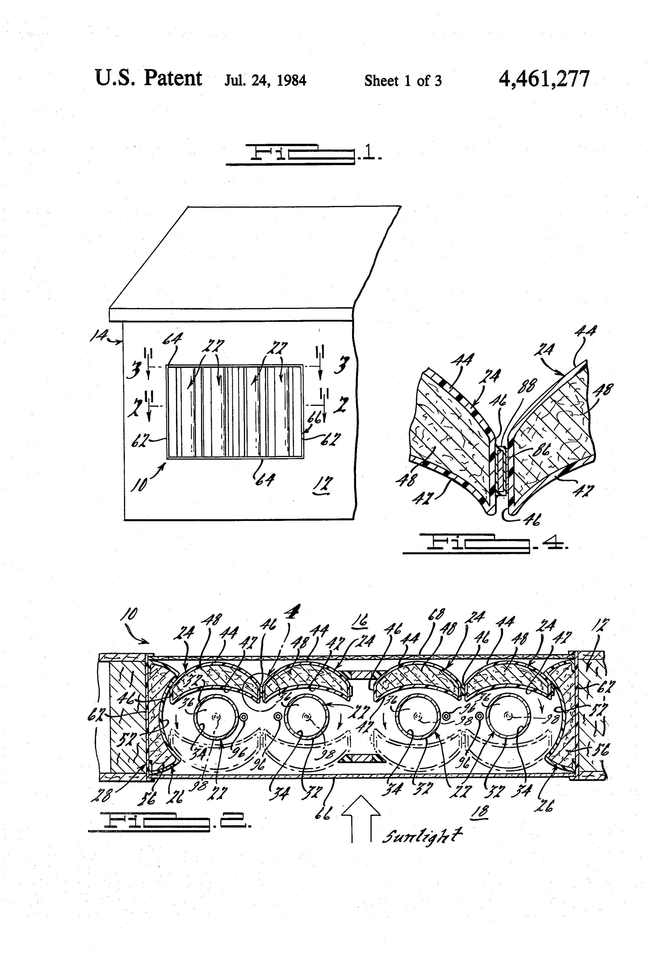
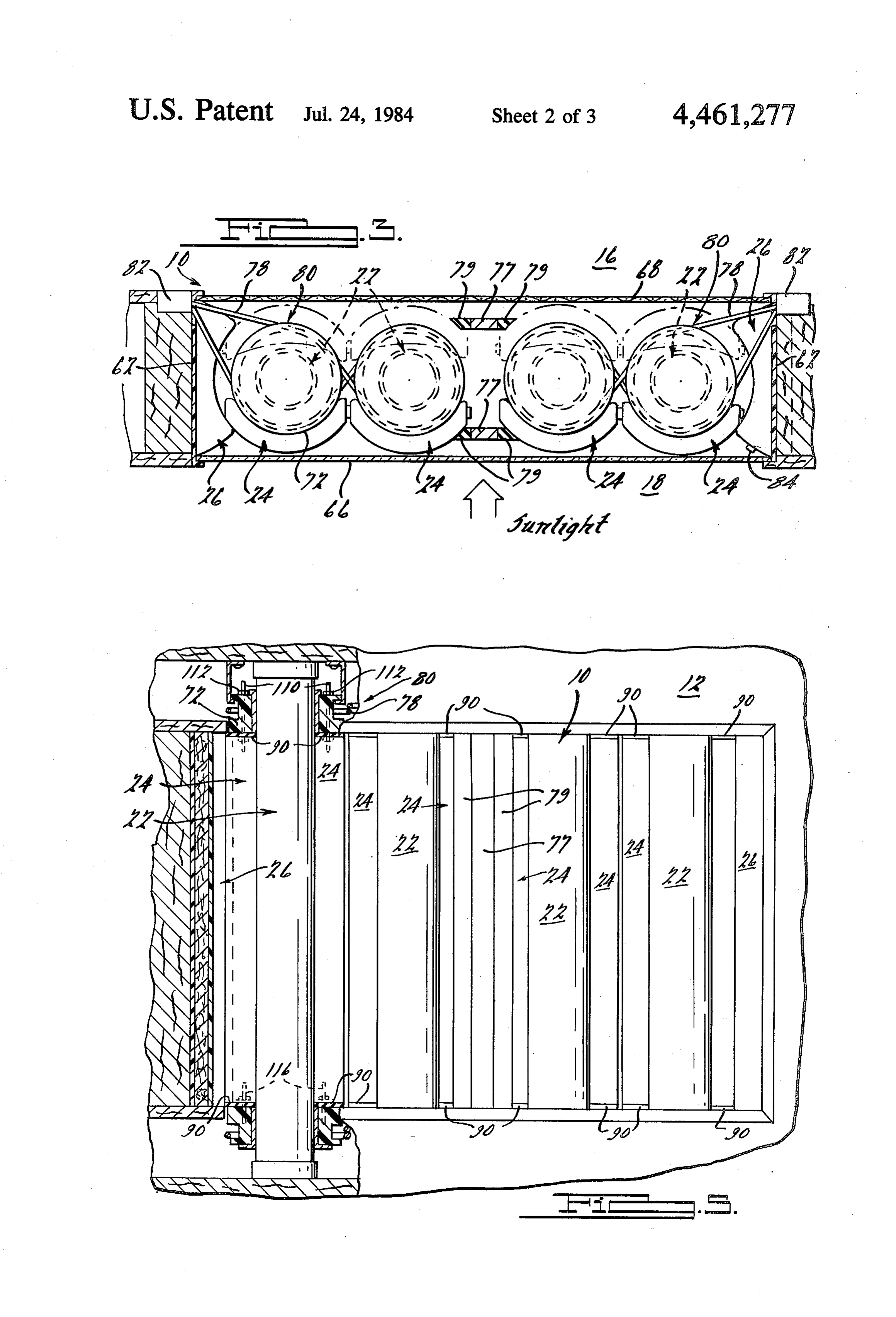
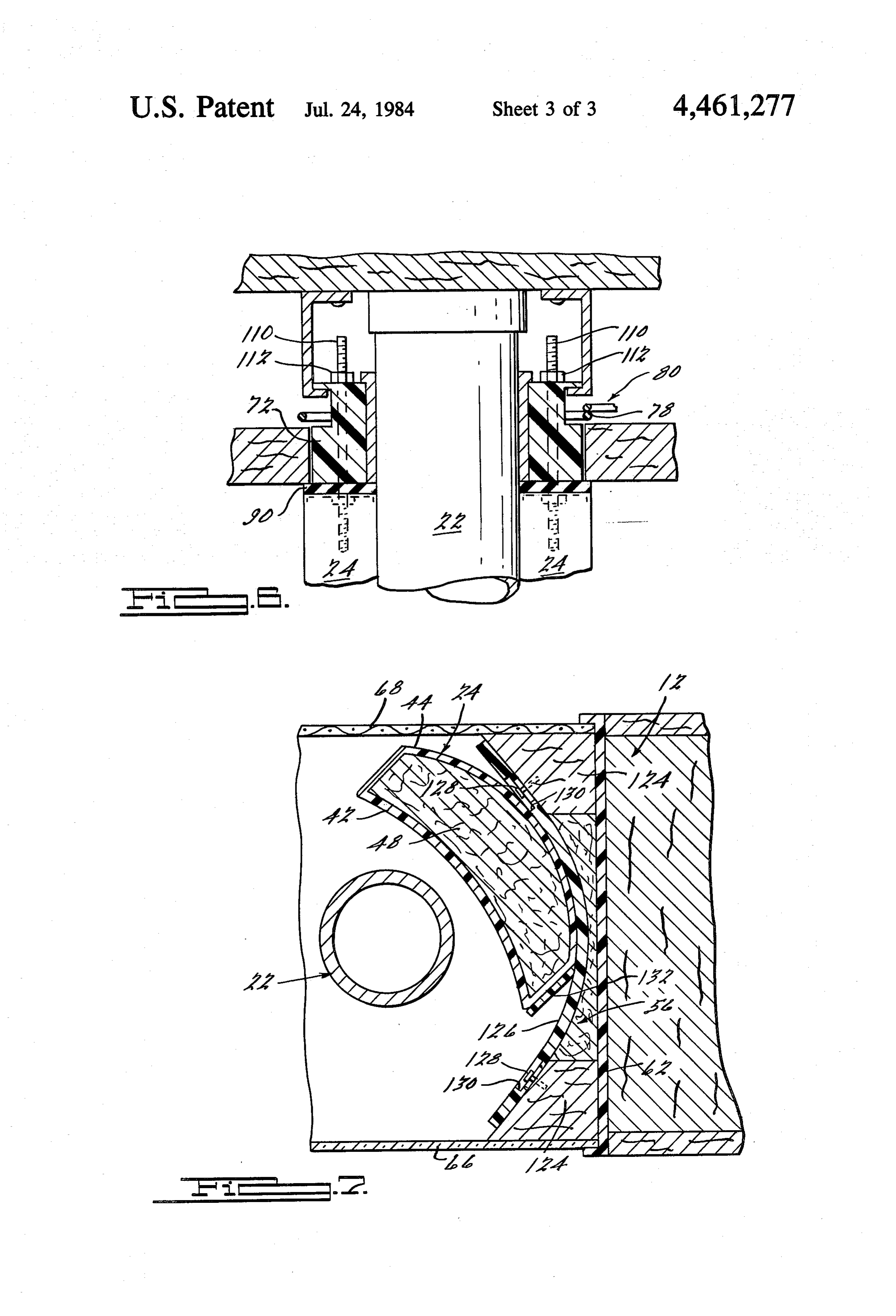
FIG. 2 is a sectional view taken along line 2-2 of
Page 2drawing sheetscan →
Page 3drawing sheetscan →
Page 4drawing sheetscan →
Page 5scan →
of a thermal energy transfer device according to the
THERMAL ENERGY TRANSFER DEVICE present invention.
FIG. 2 is a sectional view taken along line 2-2 of
BACKGROUND AND SUMMARY OF THE FIG. 1, illustrating the movable reflectors of the energy INVENTION transfer device in a first rotated position.
The invention relates generally to energy collection FIG. 3 is a sectional view taken along line 3-3 of and transfer apparatus and more specifically to such FIG. 1, illustrating the movable thermal reflectors ro apparatus for heating and cooling building structures tated to a second position and further illustrating an primarily by means of the collection and dissipation of 10 actuation system for the movable reflectors. solar and other radiant energy, as well as by convective FIG. 4 is an enlarged, detailed sectional view of the and conductive heat transfer. lateral edge areas of the movable thermal reflectors, The dramatic increase in the cost of energy in recent illustrating sealing means therebetween. years, coupled with the concern for conservation of FIG. 5 is an elevational view of an exterior wall of a non-renewable energy sources, has encouraged the 15 building structure, viewed from the interior thereof, development of various devices and systems for con illustrating the thermal energy transfer device of FIG. 1 verting solar energy into more readily-usable energy and the details of the construction thereof. forms as well as for reducing the energy used in heating FIG. 6 is an enlarged detailed view of the upper end and cooling building structures. Such prior develop of one of the collector and movable reflector assem ments include various collection devices positioned for blies, illustrating the details of the construction thereof. direct exposure to the sun, various devices for directing FIG. 7 is an enlarged partial section view of the en and concentrating the sun's radiant energy onto thermal ergy transfer device, similar to that of the full view collectors, and apparatus for selectively blocking such shown in FIG. 2, but illustrating an optional deflectable exposure to the sun's rays under predetermined condi fixed reflector.
tions. While many of such prior devices have been 25 found to be fairly effective, they have frequently been DETALEED DESCRIPTION OF THE inordinately expensive and complex. Furthermore, PREFERRED EMBODIMENTS many of such prior developments have not taken full FIGS. 1 through 5 of the drawings depict exemplary advantage of the potential of solar energy for year preferred around heating and cooling purposes, both during the according embodiments of an energy transfer device day and the night, and have generally required addi 30 exterior wall of a buildinginvention to the present structure as installed in an for purposes of tional apparatus or systems for cooling the interior of illustration only. One skilled in the art will building structures. The need has continued, therefore, ognize from the following discussion that thereadily rec principles for relatively simple and inexpensive solar energy trans of the invention are equally applicable to installations of fer systems which efficiently and effectively convey the the thermal energy transfer device in a roof stored thermal energy to the interior of the building exterior building panels and to energy transfer appara structure and which also may be used to cool the build tus other than that shown in the drawings. ing or to supplement the building's conventional cool In FIG. 1, an exemplary energy transfer device ac ing system in order to reduce energy usage and cost on cording to the present invention is indicated generally a year-around basis.
In accordance with the present invention, a thermal by reference numeral 10 and is shown for purposes of energy transfer device adapted for installation in an illustation as installed in an exterior wall 12 of a building exterior wall or roof of a building structure generally structure 14. The energy transfer device 10 may alterna includes collector means for receiving and storing ther tively be installed in a roof or other exterior partition of mal energy from either the exterior or interior of the the building structure 14. As is further illustrated in FIGS. 2 and 3, the energy transfer device 10 generally building structure. The device also includes movable 45 includes thermal reflector means, which are preferably ther a number of high-capacity thermal energy mally insulated, for alternatively concentrating thermal collectors 22, a corresponding number of associated energy from the surroundings on to the collector means movable thermal reflectors 24 (which preferably also or dispersing thermal energy from the collector means serve as insulators), at least a pair of fixed thermal re into the surroundings, and actuating means for rotating 50 flectors 26, and a frame structure 28 generally surround the movable reflector means about the collector means ing and supporting the other components of the energy in order to accomplish such alternative purposes. Pref transfer device. Although the energy transfer device 10 erably, the thermal energy transfer device includes is shown in the drawings with its axially-extending col redundant fixed reflector means which cooperate with lectors 22 in a vertical orientation, it should be empha the movable reflector means to optimize the amount of 55 sized that the collectors may alternatively be disposed energy collected or dispersed. The device may also in horizontal or other orientations.
optionally include movable reflectors and other compo In one form of the invention, each of the thermal nents that are transparent or semi-transparent, thereby energy collectors 22 includes a generally hollow outer making the device especially applicable for window casing 32, which has a thermally absorptive outer sur installations. 60 face and is closed at both ends, forming a central hollow Additional advantages and features of the present core 34 therein. Contained within the core 34 is a high invention will become apparent from the following thermal capacity material 36 capable of collecting and description and from the appended claims taken in con storing energy. Such materials, may be of the phase junction with the accompanying drawings. change type well-known to those skilled in the art and 65 have the capability of being solid generally at a prese
BRIEF DESCRIPTION OF THE DRAWINGS lected desired room temperature and have a phase FIG. 1 depicts a partial elevational perspective of a change temperature in a comfort range of approxi building structure, illustrating an exemplary installation mately 60 F. to approximately 90F. in order to melt and 6 become liquid generally at such room temperature associated collectors 22 and the exterior 18 of the build when exposed to excess thermal energy such as that ing structure, and any third position intermediate the from the sun's rays. Consequently, when exposed to a first and second positions. The movable thermal reflec decreased surrounding temperature, the phase change tors 24 are rotatable about their associated collectors 22 material will convert from its liquid phase to its solid in such a manner that their inner surfaces 42 are prefera phase, giving off the previously-stored thermal energy bly maintained in an orientation facing their associated in the process. An example of a phase change material collectors 22 as the movable reflectors are rotated to or generally applicable for such purposes may be found in between their first, second and third positions. U.S. Pat. No. 4,178,727, issued to Prusinski et al, on As is shown in FIG. 4, each of the movable thermal Dec. 18, 1979. Another example is a material manufac 10 reflectors 24 may optionally have a metal or magnetic tured by Dow Chemical Co. and sold under the desig strip 86 on one of its edge portions 46 and a magnetic nation TESC-81 (XFS-43076). This Dow material com sealing strip 88 on the opposite edge portion 46. Such prises formulated chloride hexahydrate and is a thermal magnetic sealing apparatus may be of the general type energy storage compound having a melting,and solidifi and configuration commonly found on doors for refrig cation point of 81 F. Other examples of such conven 15 erators or freezers. Thus, when the movable thermal tional phase change materials convert from a liquid to a reflectors 24 are rotated to their first or second posi gaseous phase when subjected to excess thermal energy tions, the laterally-adjacent pairs of such movable re and revert back to a liquid phase when exposed to de flectors abuttingly engage one another at their edge creased surrounding temperatures, with such phase portions 46 and are substantially sealed to one another changes taking place generally at the above-mentioned 20 by means of the magnetic. engagment of the magnetic temperatures. '' strip 86 with the magnetic sealing strip 88. Alterna Alternatively, thermal energy collectors composed tively, other mutually enageable sealing means, such as of other high thermal capacity (high specific heat) ma resilient gaskets, for example, known to those skilled in terials such as concrete or other high density materials the art may be employed.
well-known to persons skilled in the art may be em 25 The thermally, reflective inner surface 42 and the ployed in lieu of, or in combination with, the phase outer surface 44 of each of the movable thermal reflec change materials within the thermal energy collectors . . tors. 24 are preferably opaque but may optionally be 22 shown in the drawings and described above. Such transparent or semi-transparent in order to allow the alternate collectors may or may not require an outer transmission of light therethrough into the interior 16 of casing, depending upon the type of materials used 30 the building structure. Whether the outer surface 44 is therein. Whether or not such a casung is required, the opaque, transparent, or semi-transparent, it may option collectors should have thermally aborptive outer sur cally be composed of athermally reflective material or faces. include a thermally reflective coating thereon for pur Generally speaking, each of the movable thermal poses of further minimizing radiant heat transfer to or reflectors 24 includes a thermally reflective, concave 35 from the interior. 16 of the building structure. Alterna inner surface 42 facing toward the collectors 22. Such tively, if the outer surface 44 is opaque, it may include inner surface 42 extends in an axial direction generally a decorative covering suited to blend with, or aestheti parallel to its associated collector 22. The inner surface cally complement, either, the exterior or interior sur 42 has an axially-extending focal locus spaced there faces, or both, of the wall partition 12. ... . . : from and located such that the associated collector 22 is 40 In the preferred form of the present invention, the positioned generally along such focal locus. Each of the fixed thermal reflectors 26 each include an axially movable thermal reflectors 24 also preferably includes a extending lateral surface 52 disposed near opposite lat convex outer surface 44 facing away from its associated eral ends of a battery of thermal energy collectors 22 collector 22. and associated movable thermal reflectors 24. Each In the preferred embodiment, the movable reflectors 45 lateral surface. 52 is concave in configuration and is 24 include thermal insulation 48 disposed between the thermally reflective for redundantly reflecting and con inner and outer surfaces 42 and 44, respectively, and centrating thermal energy from the surroundings onto contained therein by lateral edge portions 46. Although the collectors 22 or for reflecting and dispersing ther the thermal insulation 48 is depicted in the drawings as mal energy therefrom into said surroundings as is dis being composed of a fiberous or other solid material, 50 cussed in more detail below. Preferably, each fixed such as that known to those skilled in the art, other thermal reflector. 26 includes thermal insulation 56 on forms and types of thermal insulation, including a dead the opposite side of its lateral surface 52 from the collec air space, may alternatively be employed. Additionally, tors 22. Like the thermal insulation 48, discussed above, the movable reflectors 24, themselves, may be com the thermal insulation 56 may, comprise any of a number posed of materials having high thermal insulating char 55 of insulating materials or compositions well-known to acteristics. The thermal reflectors 24 also sealingly en , those skilled in the art.
gage each other, as described below, to prevent undesir The exemplary energy transfer device 10, shown for able heat gains or losses across the thermal energy de purposes of illustration in the drawings, includes a W1C. frame structure 28 as mentioned above. However, one As is described in more detail below, an actuating 60 skilled in the art will readily recognize that the collec apparatus functions to rotate each of the movable ther tors 22, the movable thermal reflectors 24, the fixed mal reflectors 42 about its associated thermal energy thermal reflectors 26, and other components and appa collector 22 from a first position indicated in solid lines ratus of the energy transfer device may optionally be in FIG. 2, wherein the movable thermal reflector is mounted or attached to a frame or other strucutral positioned between its associated collector 22 and the 65 member that is part of the exterior wall partition 12 of interior 16 of the building structure 14, a second posi the building structure. The frame structure 28 shown in tion indicated by solid lines in FIG. 3 wherein the mov the drawings preferably includes a pair of spaced-apart able thermal reflectors 24 are positioned between their lateral frame members 62 extending generally parallel 7 to the collectors 22 and disposed laterally outward from the movable reflectors and both the collars 72 and the the lateral surfaces 52 of the fixed thermal reflectors 26. frame members.
Preferably, the fixed thermal reflectors 26 are secured The cord or chain 78 may be actuated manually by to, or integrally formed with, the lateral frame members pull cords to rotate the pulleys 76 and the movable 62. The lateral frame members 62 are interconnected by thermal reflectors 24. Alternatively, an automatic con a pair of horizontal frame members 64 (see FIG. 1) to trol system, illustrated only schematically in FIG. 3 form the generally rectangular frame structure 28. The includes automatic actuators 82 which operate to rotate frame structure 28 also includes an exterior barrier 66 the movable thermal reflectors 24 in response to prede which is preferably a glazing material, such as glass or termined conditions. As will readily be appreciated by plastic, for example, which is transparent to radiant O those skilled in the art, the control system may option thermal energy transfer but substantially impervious to ally include a temperature or radiant energy sensor 84, convective energy transfer. The exterior barrier 66 is such as a photoelectric sensor, for example, and associ substantially sealingly connected to the outer edges of ated conventional controls for automatically rotating the lateral and horizontal frame members 62 and 64, the movable thermal reflectors 24 in response to a prese respectively, in order to prevent or minimize undesir 15 lected temperature or light levels in the region between able infiltration of outside air into the interior 16 of the the thermal reflectors 24 and the exterior barrier 66 in building structure and loss of thermal energy therefrom. order to detect the presence of predetermined thermal The frame structure 28 preferably includes a perfo energy levels therein. The control system may thus be rate interior panel 68 attached and substantially sealed employed to automatically regulate the energy transfer to the interior edges of the frame structure 28. The 20 device 10 as is described in more detail below. Alteran perforate panel 68 may be composed of a perforate tively, the optional automatic control system may in screen-type material of metal, plastic, or other suitable clude conventional timer means (not shown) and associ materials, and is transparent to radiant and convective. ated conventional controls for rotating the movable heat transfer. The perforate barrier 68 may also be deco thermal reflectors 24 at preselected times of the day. rative to complement the interior 16 of the building 25 Referring to FIGS. 5 and 6, wherein the thermal Structure. energy device 10 is in a vertical orientation, the collar The energy transfer device 10 also includes actuation 72 at the upper end of each collector/movable reflector apparatus, generally indicated by reference numeral 80, assembly is preferably secured to its associated movable for rotating the movable thermal reflectors to and from reflector 24 by a number of threaded ajdustment rods their first, second and third positions described above. 30 110 which extend through the collar 72 and are fixedly At both ends of each of the movable thermal reflectors secured to the movable reflector 24 to support the re 24, the actuation apparatus 70 generally includes a rotat flector with the rods 110 in tension loading. An inter able collar 72 disposed around the associated collector nally threaded nut 112 threadably engages the upper 22 for slidable rotation relative thereto. The collar 72 is end of each adjustment rod 110 and bears against the secured to its associated movable thermal reflector 24, 35 collar 72. By rotating the nuts 112, the vertical position by way of adjustment rods 110 and tie rods 116, and of the associated movable reflector may be raised or serves as a pulley or sheave which is rotatably actuated lowered to facilitate the free rotation thereof between by a cord or chain 78 to rotate the thermal reflector 24. the upper and lower collars 72. The lower tie rods 116 The cord or chain 78 preferably engages the various are fixedly secured to their associated movable reflec collars 72 in the energy transfer device in such a manner 40 tors 24, but are only slidably received in corresponding that actuation of the cord 78 causes laterally-adjacent bores in the lower collar 72. The tie rods 116 thus serve collars 72 to rotate in a coordinated manner in opposite to laterally align the movable reflectors with the lower directions thereby correspondingly rotating each pair collars 72 and to transmit rotation of the lower collars of laterally-adjacent movable thermal reflectors 24 in a to their associated movable reflectors. One skilled in the coordinated manner in opposite directions. Thus, for 45 art will readily recognize that similar supporting appa example, the movable thermal reflector 24 at the left ratus may be employed in installations wherein the ward end of the energy transfer device, as viewed in thermal energy device is oriented other than vertically. FIG. 3, preferably rotates in a clockwise direction when FIG. 7 illustrates an optional construction and config rotated from its second position shown in phantom lines uration of the fixed thermal reflectors. In such an op to its first position shown in solid lines. Accordingly, SO tional arrangement, the fixed thermal reflectors 26 of the next laterally-adjacent movable thermal reflector in FIGS. 1 through 6 are replaced by at least a pair of FIG. 3 preferably moves in a counterclockwise direc support members 124 and optional fixed thermal reflec tion when rotated from its second position to its first tors 126. The optional fixed thermal reflectors are gen position. The remaining movable reflectors, as viewed erally resilient and flexible in order to deflect as they are from left to right in FIG. 3, are rotated by the actuation 55 slidingly engaged by the associated movable reflectors apparatus 70 in alternate clockwise and counterclock 24 as the movable reflectors are rotated to their various wise directions in order to prevent the reflectors from positions.
interfering with each other during rotation. Further In order to provide for a tight sealing engagement more, to prevent such interference between laterally with the movable reflectors 24, the optional fixed ther adjacent pairs of the movable thermal reflectors, each 60 mal reflectors are urged into a generally concave con such pair is preferably separated by axially-extending figuration and attached to the support members such insulated stop members 77. Each of the insulated stop that they are internally and resiliently biased generally members 77 preferably includes a sealing strip 79 at toward their adjacent collectors 22. Thus, when the each of its lateral edges for sealingly engaging the mov movable reflectors 24 are rotated into sliding engage able thermal reflectors 24 to minimize the infiltration of 65 ment with the optional fixed reflectors 126, the fixed outside air into the interior 16. Preferably, the upper reflectors 126 resiliently deflect to sealingly conform to and lower ends of the movable reflectors 24 each in the engaged portion of the movable reflectors and to be clude a sealing member 90 for providing a seal between sealingly and slidingly engaged by a sealing strip or 8 member 132 on at least one edge portion of the movable stored thermal energy, but without undergoing a reflectors. The internal resilient biasing force of the change in phase. It should also be noted that in the reflectors 126 maintains such sealing engagement dur preferred embodiment, wherein the movable thermal ing the movement of the movable reflectors in order to reflectors include thermal insulation 48 therein, such substantially prevent undesirable air flow between the 5 movable reflectors also serve to insulate both the inte fixed and movable reflectors. rior 16 of the building structure and the collectors from In order to accommodate the resilient deflection of the exterior 18 and to minimize the heat loss across the the optional fixed thermal reflectors 126, guide fasteners energy transfer device 10.
128 are received within elongated slots 130 in the reflec In the summer mode of operation, the above tors 126 and are secured to the support members 124. 10 described rotations of the movable thermal reflectors 24 The elongated slots 130 are recessed or countersunk to are reversed. During the daylight hours, the movable allow the heads of the guide fasteners 128 to be disposed thermal reflectors 24 are rotated to their second posi beneath the surface of the reflectors 126, thereby avoid tions between the collectors 22 and the exterior barrier ing interference between the guide fasteners 128 and the 66, as shown in solid lines in FIG. 3, in order to shade movable reflectors 24. Such a construction permits a 15 the interior 16 of the building structure from undesir limited slidable movable movement of the optional fixed able heat gain by way of radiant heat transfer of solar reflectors 126 relative to the support members as they energy. Also, the thermal energy in the interior 16 of deflect. the building structure is reflected and concentrated The operation of the energy transfer device 10 of the onto the collectors 22 by the movable thermal reflectors present invention may be described generally as fol 20 24 and the fixed thermal reflectors 26 or 126 in order lows. For winter or other cold weather operation, the that said energy may be absorbed by the collectors, movable thermal reflectors 24 are rotated during day thereby cooling the interior of the building. Conversely, light hours to their first positions between the collectors during the night hours, the movable thermal reflectors 22 and the perforate panels 68, as shown in solid lines in 24 are rotated to their first positions between collectors FIG. 2, in order to reflect and concentrate solar energy 25 22 and the perforate panel 68, as shown in solid lines in or other radiant thermal energy from the surroundings FIG. 2, in order to reflect and disperse the previously onto the collectors 22. Additionally, the redundant stored thermal energy from the collectors 22 to the cool fixed thermal reflectors 26 or 126 also reflect and con dark exterior 18 of the building structure primarily by centrate ambient thermal energy from the exterior of means of the radiant heat transfer. During both daylight the building structure onto the collectors, as well as 30 hours and night hours, the energy transfer device 10 reflecting and concentrating thermal energy from the preferably insulates the interior 16 of the building struc collectors back to the collectors themselves. Thus dur ture from the exterior 18 by means of thermal insulation ing daylight hours, the collectors 22 receive and store 48 and 56, in the movable and fixed reflectors, respec thermal energy both by direct radiant heat transfer and tively.
by reflected radiant heat transfer. If the high thermal 35 During moderate temperature conditions, such as in capacity collectors employed in the thermal energy the spring or fall, the thermal reflectors 24 may be ro transfer device are the phase change type described tated to any third position, intermediate the first and above in connection with one form of the invention, the second positions, described above. Such intermediate material 36 within the core 34 of the collectors under positions allow the direct transmission of light into the goes a phase change from the solid phase to the liquid 40 interior of the building structure when heating or cool phase (or alternatively from the liquid phase to the ing is not necessary or desired.
gaseous phase) in order to store such thermal energy. If If the optional automatic control system, described sufficient ambient thermal energy is available such above and shown schematically in FIG. 3, is employed phase change material will also increase in temperature, in conjunction with the energy transfer device 10, the thereby storing additional amounts of thermal energy. 45 control system may optionally include a so-called "sum Similarly, if the collectors 22 are the high-density type mer/winter switch' and associated conventional con described above in connection with another form of the trols, both of which are well-known to those skilled in invention, such high-density material will increase in the art. By use of such a summer/winter switch the temperature to store thermal energy, but without un automatic control system may be manually, or even dergoing a change in phase. 50 automatically, switched to convert the energy transfer During the night hours in such winter mode of opera device 10 from its summer mode of operation to its tion, the movable thermal reflectors 24 are rotated to winter mode of operation and vice versa. their second positions between the collectors 22 and the A number of additional optional variations on the exterior barrier 66, as shown in solid lines in FIG. 3, and energy transfer device 10 as described above may be function to reflect and disperse the previously-stored 55 employed to further maximize the utility of the system thermal energy from the collectors 22 to the interior 16 or to adapt the system to the conditions or requirements of the building structure. Simultaneously, the redundant of a given application. For example, the thermal energy fixed thermal reflectors 26 or 126 also reflect and dis device may even alternately include an interior barrier perse such stored thermal energy from the collectors to (not shown) that is integral with the interior side of the the interior of the building structure. During such dis 60 wall partition and includes upper and lower louvres or persal of thermal energy into the building interior, the registers. By providing such louvres in such an integral phase change material 36, in the case of the phase interior barrier, air in the interior of the building struc change type of collectors 22, lowers in temperature and ture may circulate through, and be convectively heated undergoes another phase change from liquid to solid, by, the energy transfer device by passing first through (or alternatively from gaseous to liquid) in order to give 65 the lower louvre, flowing over the collectors, and then off its previously-stored thermal energy. In the case of exiting into the interior of the building structure the high-density type thermal collectors, the high-den through the upper louvres. It should also be noted that sity material also lowers in temperature to give off although such integral interior barrier may alternately
Page 9scan →
9 O be employed, the perforate panel 68 is preferred and is movable reflector means and said collector means, believed to more efficiently employ the principles of the said fixed reflector means having a thermally re invention, flective concave lateral surface thereon facing It should also be emphasized that in any of the em toward said collector means; and bodiments described herein, convective heating by actuating means for rotating said movable reflector means of interior air passing through the energy device means about said collector means to a first position 10 is supplemental to the primarily-radiant heat transfer wherein at least a portion of said movable reflector previously described and further that at least some de means is positioned between said collector means gree of conductive heat transfer between the collectors and the interior of building structure, to a second and the structural components of the energy transfer 10 position wherein at least a portion of said movable device 10 and the building structure 14 also serves to reflector means is positioned between said collec transfer thermal energy into or from the interior 16 of tor means and the exterior of said building struc the building structure. ture, or to any third position intermediate said first Another optional variation on the energy transfer and second positions, said inner surface facing said system described above includes the addition of con 15 collector means as said movable reflector means is duits 96 (as shown in solid lines in FIG. 2), which con rotated to or between any of said first, second and tain water or other heat transfer fluids and extend in an third positions.
axial direction generally parallel to, and between, later 2. A thermal energy transfer device according to ally-adjacent collectors 22. Such conduits serve to con claim 1, wherein said movable reflector means includes vey the water or other heat transfer fluid to the energy thermal insulation means between said inner and outer transfer device 10 in close proximity to the collectors 22 surfaces.
in order to transfer thermal energy from the collectors 3. A thermal energy transfer device according to to the water or other heat transfer fluid, thereby raising claim its temperature and returning it to the building structure surface1, haswherein said thermally reflective concave inner a focal locus spaced therefrom, said collec in order to supplement a conventional water heating 25 tor means being positioned generally along said focal apparatus or other energy conversaion device. Alterna locus, said movable reflector means being adapted to tively, or additionally, such conduits 96 may be con reflect and concentrate thermal energy from the sur nected to conventional interior cooling apparatus and roundings onto said collector means and further being may be used during the warm weather months to supply adapted to reflect and disperse thermal energy from said cooled water or other cooled heat transfer fluids to the 30 energy transfer device 10 in order to supplement the collector means into the surroundings. 4. A thermal energy transfer device according to cooling of the interior and even more effectively re claim 3, wherein said inner and outer surfaces of said move the thermal energy previously received and stored by the collectors 22 from the interior 16 of the movable reflector means are at least semi-transparent. building structure. Alternatively, the conduits may be 35 5. A thermal energy transfer device according to disposed within the collectors themselves, such as illus claim 3, wherein at least the outer surface of said mov trated by conduits 98 (shown in phantom lines in FIG. able6. reflector means is opaque. A thermal energy transfer device according to 2), in order to concentrate and transfer energy to or from the conduits 98 directly by way of conductive or claim 1, wherein said thermally reflective lateral surface convective energy transfer. Such conduits 98 may be 40 has a focal locus spaced therefrom, said collector means employed either in lieu of the conduits 96 or in addition being positioned generally along said focal locus, said thereto. fixed reflector means being adapted to reflect and con The foregoing discussion discloses and describes ex centrate thermal energy from the surroundings onto emplary embodiments of the present invention. One said collector means and further being adapted to re skilled in the art will readily recognize from such dis 45 flect and disperse thermal energy from said collector cussion that various changes, modifications and varia means into the surroundings.
tions may be made therein without departing from the 7. A thermal energy transfer device according to spirit and scope of the invention as defined in the fol claim 6, wherein said fixed reflector means includes lowing claims. thermal insulation means on the opposite side of said What is claimed is: 50 lateral surface from said collector means. 1. A thermal energy transfer device adapted for in 8. A thermal energy transfer device according to stallation in an exterior wall or roof of a building struc claim 1, wherein said high thermal capacity collector ture, said energy transfer device comprising: means comprises a generally hollow closed casing con at least one high thermal capacity collector means for taining a phase change material therein, said phase receiving and storing thermal energy, said collec 55 change material having a phase change temperature in a tor means extending in an axial direction; comfort range of approximately 60 F. to approximately movable thermal reflector means for reflecting ther 90 F.
mal energy to said collector means, said movable 9. A thermal energy transfer device according to reflector means having a thermally reflective con claim 8, wherein said casing has a thermally absorptive cave inner surface thereon facing toward said col 60 outer surface.
lector means and a convex outer surface facing 10. A thermal energy transfer device according to away from said collector means, said movable re claim 1, wherein said high thermal capacity collector flector means extending in an axial direction gener means comprises a high-density material adapted to rise ally parallel to but spaced from said collector in temperature when exposed to thermal energy in means; 65 order to store said thermal energy therein said adapted at least one fixed reflector means extending in an axial to release said stored thermal energy when exposed to direction generally parallel to but spaced from said surroundings having a level of said thermal energy collector means and being disposed laterally of said lower than that of said stored thermal energy.
Page 10scan →
11. A thermal energy transfer device according to second positions, said inner surface facing said claim 10, wherein said collector means has a thermally collector means as said movable reflector means is absorptive outer surface. rotated to or between any of said first, second and 12. A thermal energy transfer device according to third positions;
claim 10, wherein said high-density material is sur a frame structure generally surrounding said movable rounded by a casing having a thermally absorptive reflector means and said collector means, said outer surface. frame structure including at least a pair of spaced 13. A thermal energy transfer device according to apart frame members disposed generally laterally claim 1, further comprising convection means for circu of said movable reflector means and said collector lating air from the interior of said building structure 10 means and extending generally parallel to said col along said collector means in contact therewith and lector means, an exterior barrier being at least semi back into the interior of said building structure in order transparent and disposed between the exterior of to raise or lower the temperature of said air. said building structure and said movable reflector 14. A thermal energy transfer device according to means and said collector means, said exterior bar claim 1, further comprising conduit means extending 15 rier being substantially sealingly attached to exte within said collector means, said conduit means being rior portions of said frame structure to substantially adapted to convey a fluid therethrough, whereby ther isolate said movable reflector means and said col mal energy is transferred directly to and from said con lector means from the exterior of said building duit means by way of contact therewith. structure, said frame structure being adapted for 15. A thermal energy transfer device according to 20 installation in an opening in said wall or roof, said claim 14, wherein said means is adapted to convey a frame structure further including a perforate inte relatively cold fluid from said building structure to said rior panel being disposed between the interior of energy transfer device to be heated and returned to said said building structure and said movable reflector building structure at an elevated temperature. means and collector means; and 16. A thermal energy transfer device according to 25 a thermally reflective concave lateral surface dis claim 1, further comprising conduit means extending posed generally on each of said spaced-apart frame generally adjacent and generally parallel to said collec members and facing toward said collector means, tor means, said conduit means being adapted to convey said lateral surface having a focal locus spaced a fluid therethrough, said movable reflector means re therefrom, said collector means being positioned flecting thermal energy onto said conduit means in 30 generally along said focal locus, said lateral surface order to raise the temperaure of said fluid as it is con being adapted to reflect and concentrate thermal veyed therethrough. energy from the surroundings onto said collector 17. A thermal energy transfer device according to means and further being adapted to reflect and claim 16, wherein said conduit means is adapted to disperse thermal energy from said collector means convey a relatively cold fluid from said building struc 35 into the surroundings.
ture to said energy transfer device to be heated and 20. A thermal energy transfer device, according to returned to said building structure at an elevated tem claim 19, wherein said actuating means includes control perature. means for automatically rotating said movable reflector 18. A thermal energy transfer device, according to means from said first position to said second position claim 1, wherein said actuating means includes control when the temperature between said collector means and means for automatically rotating said movable reflector said exterior barrier reaches a first predetermined level means from said first position to said second position in and for automatically rotating said movable reflector response to predetermined ambient radiant energy lev means from said second position to said first position els on the exterior of said building structure. when said temperature reaches a second predetermined 19. A thermal energy transfer device adapted for 45 temperature.
installation in an exterior wall or roof of a building 21. A thermal energy transfer device adapted for structure, said energy transfer device comprising: installation in an exterior wall or roof of a building at least one high thermal capacity collector means for structure, said energy transfer device comprising: receiving and storing thermal energy, said collec at least one high thermal capacity collector for re tor means extending in an axial direction, 50 ceiving and storing thermal energy, said collector movable thermal reflector means for reflecting ther extending generally in an axial direction and con mal energy to said collector means, said movable taining a high thermal capacity material therein; reflector means having a thermally reflective con a movable thermal reflector associated with said col cave inner surface thereon facing toward said col lector having a thermally reflective concave inner lector means and a convex outer surface facing 55 surface facing toward said collector and extending away from said collector means, said movable re generally parallel to but spaced from said collector, flector means extending in an axial direction gener said inner surface having a focal locus spaced ally parallel to but spaced from said collector therefrom and extending in said axial direction, said means; collector being positioned generally along said actuating means for rotating said movable reflector 60 focal locus of said inner surface, said inner surface means about said collector means to a first position being adapted to reflect thermal energy between wherein at least a portion of said movable reflector said collector and the surroundings, said movable means is positioned between said collector means reflector further having a convex outer surface and the interior of building structure, to a second facing away from said collector and thermal insula position wherein at least a portion of said movable 65 tion means disposed between said inner and outer reflector means is positioned between said collector surfaces;
means and the exterior of said building structure, or at least one fixed reflector disposed laterally of said to any third position intermediate said first and movable reflector, said fixed reflector having a 11 thermally reflective concave lateral surface facing 28. A thermal energy transfer device according to toward said collector and extending in an axial claim 27, wherein said frame structure further com direction generally parallel to but spaced from said prises a pair of spaced-apart second frame members collector, said lateral surface having a focal locus interconnecting said spaced-apart first frame members, spaced therefrom and extending in said axial direc said actuating apparatus including pulley means rotat tion, said collector being positioned generally ably attached to said second frame members and se along said focal locus of said lateral surface, said cured to said movable reflector, said pulley means fur lateral surface being adapted to reflect thermal ther being rotatable relative to said collector in order to energy between said collector and the surround rotate said movable reflector about said collector. ings, said fixed reflector further including thermal 10 29. A thermal energy transfer device according to insulation disposed on the opposite side of said claim 28, further comprising automatic control means lateral surface from said collector; for automatically rotating said movable reflector from an actuating apparatus for rotating said movable re one of said first and second positions to the other of said flector about said collector to a first position first and second positions in response to a predeter wherein at least a portion of said movable reflector 15 mined temperature level between said movable reflec is positioned between said collector and the inte tors and said exterior glazing barrier. rior of building structure, to a second position 30. A thermal energy transfer device according to wherein at least a portion of said movable reflector claim 27, including a plurality of said collectors and is positioned between said collector and the exte 20 corresponding associated movable reflectors arranged in a number of laterally-adjacent pairs in said frame rior of said building structure, or to any third posi structure, said actuating apparatus being adapted to tion intermediate said first and second positions, rotate the laterally-adjacent movable reflectors of each said inner surface of said fixed reflector facing said of said pairs in opposite directions between their respec collector as said movable reflector is rotated to or between either of said first and second positions. 25 tive first and second positions, each of said movable 22. A thermal energy transfer device according to thereof forhaving reflectors sealing means on an edge portion mutually-abutting sealing engagement with claim 21, wherein said collector has a thermally absorp one another when in their respective first and second tive outer surface.
23. A thermal energy transfer device according to positions, one of said fixed reflectors being located at claim 21, wherein said high thermal capacity collector 30 each lateral end of said pairs of collectors and associated movable reflectors.
comprises a generally hollow closed casing containing a 31. A thermal energy device according to claim 30, phase change material therein, said phase change mate further rial have a phase change temperature in a comfort range portion including of said sealing means on at least one axial end movable reflectors for sealing engage of approximately 60 F. to approximately 90 F. ment with said actuating apparatus and with said frame 24. A thermal energy transfer device according to 35 Structure.
claim 23, wherein said casing has a thermally absorptive 32. A thermal energy transfer device according to outer surface. claim 21, further comprising automatic control means 25. A thermal energy transfer device according to for automatically rotating said movable reflector from claim 21, wherein said high thermal capacity collector comprises a high-density material adapted to rise in one of said first and second positions to the other of said first and second positions in response to predetermined temperature when exposed to thermal energy in order radiant energy levels at the exterior of said building to store said thermal energy therein and adapted to Structure.
release said stored thermal energy when exposed to 33. A thermal energy transfer device according to surroundings having a level of said thermal energy claim 21, wherein said actuation apparatus includes lower than that of said stored thermal energy. 45 means for selectively adjusting the axial position of said 26. A thermal energy transfer device according to movable thermal reflector in order to facilitate the free claim 25, wherein said high-density material is sur movement thereof.
rounded by a casing having a thermally absorptive 34. A thermal energy transfer device according to outer surface. claim 21, wherein said fixed reflector is resiliently de 27. A thermal energy transfer device according to 50 flectable and exerts a resilient biasing force directed claim 21, further comprising a generally rectangular generally toward said collector in order to maintain a frame structure including at least a pair of spaced-apart slidingly and sealingly engagement between said fixed first frame members disposed laterally relative to said reflector and said movable reflector as said movable movable reflector and extending in an axial direction reflector is moved to or between said first and second generally parallel to said collector, one of said lateral 55 positions, said fixed reflector deflecting in response to surfaces of said fixed reflectors being disposed along said sliding and sealing engagement. each of said first frame members, an exterior glazing 35. A thermal energy transfer device according to barrier substantially sealingly attached to an exterior claim 34, further comprising support means for said portion of said frame structure, said exterior glazing fixed reflector, and guide means for attaching said fixed barrier being disposed between the exterior of said 60 reflector to said support means for limited slidable building structure and said collector, said frame struc movement relative thereto in order to accommodate ture further being adapted for installation of said energy said deflection of said fixed reflector. transfer device in an opening in said wall or roof. sk k sk :k ck
Page 12scan →
United states patent and trademark office
Certificate of correction
INVENTOR(S) : Jorge Pardo
It is certified that error appears in the above-identified patent and that said Letters Patent is hereby Corrected as shown below:
Col. 3, line 13, after "formulated" insert --calcium Col. 3, line 3l, "casung" should be -casing Col. 5, line 65, after "minimize" delete -the Col. 6, line 20, "Alteran-" should be --Alterna--- Col. 8, line 29, after "of" delete -the
Col. 10, line 65, delete "said" (second occurrence) and insert therefor eigned and escaled this
Seal
Attest:
Donald j. quigg
Attesting Officer Acting Commissioner of Patents and Trademarks
Provenance
- Collection
- Patents citing this work
- Pages
- 12
- Method
- pdftotext (the PDF's own text layer) + pdftoppm 300dpi page scans
- Patent office record
- patents.google.com →
- Source
- Google Patents citing-documents table
- Assignee
- Jorge Pardo
- Published
- 1984-07-24
- Transcribed from
- patentimages.storage.googleapis.com →