

patent · US4452229A
Thermal heat storage and cooling system
5 June 1984
Text
Page 1bibliographic recordscan →
United States Pater at 19 11 4,452,229 Powers Jun. 5, 1984 (54) THERMAL HEAT STORAGE AND COOLING 4,196,719 4/1980 Skrivseth ............................ 126/430 SYSTEM 4,207,868 6/1980 Peterson. ... 126/449 4,213,447 7/1980 Erickson . . 126/430 76 Inventor: Kim Powers, 2740 Kiawah Ave., 4,286,575 9/1981 Gates ................................... 126/429 Columbia, S.C. 29205 4,304,219 12/1981 Currie ................................. 126/429 4,350,200 9/1982 McElwain. ... 165/48 S 21 Appl. No.: 321,222 4,373,573 2/1983 Madwed ............................. 126/429 (22 Filed: Nov. 13, 1981 Primary Examiner-Samuel Scott Int. Cl. .............................................. F2SB 13/00 Assistant Examiner-Noah P. Kamen 52 U.S. Cl. .................................... 126/429, 126/400. Attorney, Agent, or Firm-Benoni O. Reynolds 126/436; 126/430; 165/45 57 ABSTRACT Field of Search ............... 126/429, 430, 436, 400, - 126/422, 165/45, 48 s An improved heat storage and cooling system utilizing a conventional solar energy collector as a heat source, a (56) References Cited thermal mass of stacked cement blocks with interal
o air storage and a dual-purpose structural wall of stag
gered hollow system is cement blocks self-contained and
generate cool air.located
The 4024910 5/1977 Werner ................................. 165/45 either in a fully bermed room adjacent on any side to the 4,033,130 7/1977 Hermans ...... ... 126/400 area to be serviced or in a basement room embedded in 4,051,999 10/1977 Granger et al. ... 126/429 the earth beneath the area to be serviced. The circula 4,088,115 5/1978 Powell ................. ... 126/429 tion system of metal ducts, pipes, air handler, circulat 4,088,266 5/1978 Keyes............... 126/29 ing fan, gas heater and dampers interconnects the solar 4,121,764 10/1978 Hope et al. ... ... 237/1 A energy collector, the thermal mass and cooling walls to 2E 2.2. his 23%, provide seven modes of operation for the storage of 4,138.66 2/1979 Besack .......... ... 23/A heat or cold and the circulation of warm or cool air as 4,149,520 4/1979 Arent ........... 126/270 circumstances may require.
4,160,443 7/1979 Brindle et al. ... ... 126/270 4,173,304 11/1979 Johnson .............................. 237/1 A 8 Claims, 5 Drawing Figures
ataaaaaaaaaaaaaaaaaaaaaaaaaaaaate
4 ZZZZZZAaaaySAZZZZZZYSSYSY
NYNYNYZZZZZZZNYYYYYYZZZZZ
SNNNNNYZZZZZZPNvvvaaZZZZZZ
22222AVY SANZZZZZZAAAAAY
Eas
SNNNNNNZZZZZZVNVVvvvZZZZZZ
ZZZZZZYYYYYZZZZZZSYYYYY
SSSNNXYZZZZZAVNVAVZZZZZZ
NNNNNNNZZZZZZNYYYYZZZZZZ
ZZZZZZNavaya ZZZZVVVV
ZZZZZZvyavarzazaarxxxyy
SSNNNNYYZZZNYSSZZZZZ
() SSAYSSSZZZZZZYYYZZZZZZ
ZZZZZZANalyvayZZZZZNyaya
2ZZZZYava Nayaay
Drawings
Page 2drawing sheetscan →
Page 3drawing sheetscan →
Page 4scan →
magnesium additive increases the thermal conductance
THERMAL, HEAT STORAGE AND COOLNG of the cement blocks. These blocks have their apertures SYSTEM communicating with one another so as to form a series
Background of invention
of horizontal passageways for air through the interior of 5 the thermal mass. This thermal mass also can be utilized (1) Field of Invention as a backup unit for storage of cold as an alternative This invention relates to thermal heating and cooling mode of operation.
systems for generating, storing and circulating warm Cooling is provided by a series of interconnecting and cool air primarily for residential use. More particu 10 cooling walls comprised of staggered hollow cement larly it relates to heat storage and cooling apparatus for blocks whose apertures are positioned so as to permit homes. continuous air movement horizontally and vertically (2) Description of Prior Art through the interior of the interconnecting cooling The high cost of utilities has spurred on many efforts walls. These interconnecting cooling walls serve a dual to collect solar energy for heating purposes. Similar 15 purpose of providing structural support for the room attempts have been made to utilize rocks or earth for the enclosure and generating cool air. storage of heat or cold for future use. However, most of A circulation system interconnects the solar energy the prior art has been single purpose in that the systems collector, the thermal mass, the cooling walls and the developed have addressed solely the collection and area to be heated or cooled. This circulation is provided storage of heat or the collection and storage of cold air. by a network of metal ducts, pipes, an air handler, a Few systems have been addressed to both objectives. 20 circulating fan, a gas heater and dampers, all adapted so By far, the majority effort has dealt with heating objec as to provide the following seven modes of operation, as tives with less emphasis on the cooling aspects. Further, heating and cooling needs might dictate: the systems that have evolved in the prior art have been designed solely to collecting or storing energy, with conveying1-heating
Mode heat area to be heated on sunny days by from said solar energy collector little or no thought given to other possible utilitarian 25 through said storage means to area to be heated such as objectives such as structural support. a house. s: ...' . . Many different media have been used for the storage Mode 2-heating area to be heated on cloudy days or of heat or cold. Rock has been used for heat storage and evenings the earth, as well as extensive underground ducting, has to area tobyberecirculating heat from said storage means been used for the generation of cool air. The inefficency 30 storage means,heated such as a house and return to said or the high cost of most such apparatus has limited their Mode 3-recharging said storage means with heat on large scale utilization by the general public. Many sys Sunny days by recirculating warmed air from said solar tems are not only expensive to install but pose mainte nance problems as well. energy collector to said storage means and return to Many of the thermal heat storage systems in the prior 35 saidMode solar energy collector, 4-heating area to be heated on-cloudy days or art failed to provide for the generation of cool air as an alternative mode of operation. Those systems which did evenings by circulating heat from said gas heater to area include this alternate mode, did so inadequately. to be heated such as a house, . . . . . Although berming is not new in the art, the technique Mode 5-cooling area to be cooled on warm days or has been used only in a limited fashion. Usually it has 40 evenings by conveying cooled air from said cooling been used independently in improving thermal retentiv means to the area to be cooled, such as a house, ity by piling earth partially around the outside walls of Mode 6-charge said storage means as a backup cold a home. None of the prior art, as reviewed by this in air storage unit by circulating cool night air from out ventor, has utilized the full potential of energy savings. side to said storage means through the area to be cooled, His technique could provide for homes built on con 45 such as a house, and return to said storage means. Once crete slabs with topography unsuited to conventional charged with cool air, said storage means is a source of berming treatments, an area not adequately explored in cooling for future utilization using Mode 2, the prior art. Mode 7-heating area to be heated directly on sunny Prior art known to this inventor includes the follow days by conveying warmed air from said solar energy ing U.S. Pat. Nos.: 965,391, 7/1910, Little; 4,024,910, 50 collector to the area to be heated, such as a house, by 5/1977, Werner; 4,121,764, 10/1978, Hope et al; passing said storage means.
4,138,061, 2/1979, Besack; 4,149,520, 4/1979, Arent; The thermal mass and cooling walls disclosed are 4,160,443, 7/1979, Brindle; 4,173,304, 11/1979, Johnson; enclosed either in a room external to the structure to be 4,196,719, 4/1980, Skrivseth; 4,207,868, 6/1980, Peter serviced or beneath such structure. The room external SO 55 to the area to be heated or cooled is attached thereto on
Brief summary of invention
any side and is bermed completely on all exposed struc tural walls. These structural walls are interconnected
The present invention is an improved thermal heat with the circulation system described above and are a storage and cooling system which is amenable to either series of interconnecting cooling walls comprised of manual or automatic operation as heating or cooling 60 staggered hollow cement blocks whose apertures are needs might dictate. The system utilizes a conventional positioned and adapted so as to permit continuous air solar energy collector which could be mounted on a movement horizontally and vertically through the inte roof, in an attic or atop the bermed room which is an rior of said interconnecting cooling walls which walls alternative enclosure for the heat storage and cooling and room are capped by a superinsulated roof. media of the present invention. Heat storage is provided 65 The alternate enclosure is a basement room, embed by a superinsulated thermal mass comprising a cube of ded in the earth beneath the area to be heated or cooled, hollow cement blocks, containing a magnesium addi whose structural walls are interconnected with the tive, assembled on a superinsulated concrete slab. The circulation system described above and are a series of 5 interconnecting cooling walls comprised of staggered (6) multi-functional in that the heat storage and cool hollow cement blocks whose apertures are positioned ing means serve as structural support, backup storage, and adapted so as to permit continuous air movement or other alternate needs:
horizontally and vertically through the interior of said (7) constructed with fewer components and simpler interconnecting cooling walls which walls and room design to provide more reliable operation and less main are capped by a superinsulated roof. tenance under heavy usage conditions. In its best mode of heating operation on sunny days, Other objectives and advantages of the present inven solar heat received by the solar energy collector is tion will be apparent during the course of the following drawn by the air handler from the solar energy collec 10 detailed description.
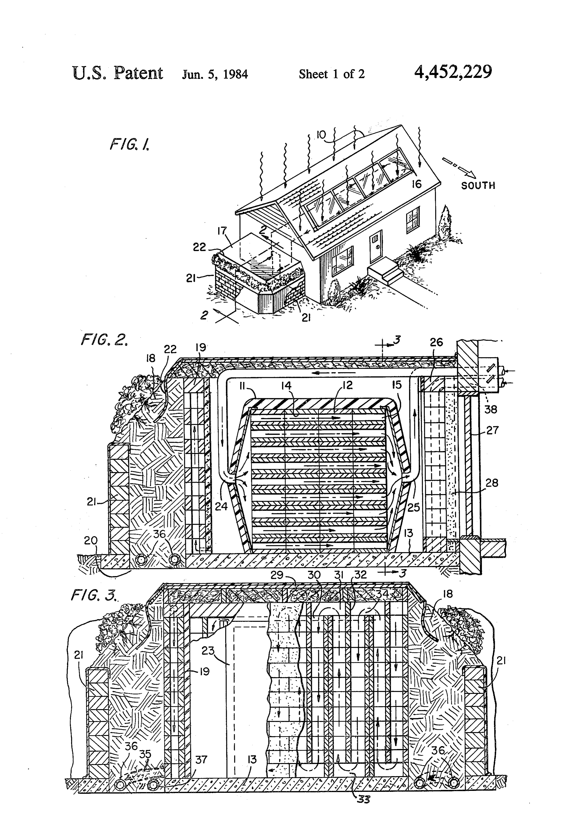
tor through the metal ducts and piping to and through BRIEF DESCRIPTION OF DRAWINGS the horizontal passages for air in the thermal mass and FIG. 1 is a perspective view of a thermal heat storage on into the area to be heated such as a house. The ther mal mass absorbs and retains any excess heat for future principles ofsystem and cooling the constructed in accordance with the present invention showing the above use. On cloudy days or evenings the dampers to the 15 ground version of the installation including the solar solar energy collector are closed and the heat stored in energy collector, the cinder block retaining wall for the the thermal mass is recirculated to the area to be heated bermed enclosure, the vegetation planted atop the berm and back to the thermal mass by the air handler. An and the access door to the structure to be serviced, in other alternative is to circulate warm air from the gas this example, a house.
heater to the area to be heated. 20 FIG. 2 is a side sectional view taken along line 2-2 On a sunny day, if the heat is not needed in the area of FIG. 1 showing the details of the berming construc to be heated, the dampers to the ducts servicing that tion, the cooling walls and the horizontal passageways area can be closed, the dampers to the solar energy for air through the thermal mass.
collector can be opened and the circulating fan can be FIG. 3 is a rear sectional view taken along line 3-3 turned on to pull heat from the solar energy collector 25 of FIG. 2 showing the details of the roof construction only to the thermal mass and back to the solar energy and supporting walls of the bermed room, as well as the collector as a means of recharging the thermal mass arrangement of the staggered hollow cement blocks of with heat for future use. the cooling walls positioned and adapted to permit the In the best mode for the generation and circulation of flow of cold air horizontally and vertically through the cool air, the dampers to the solar energy collector and 30 interior of the walls.
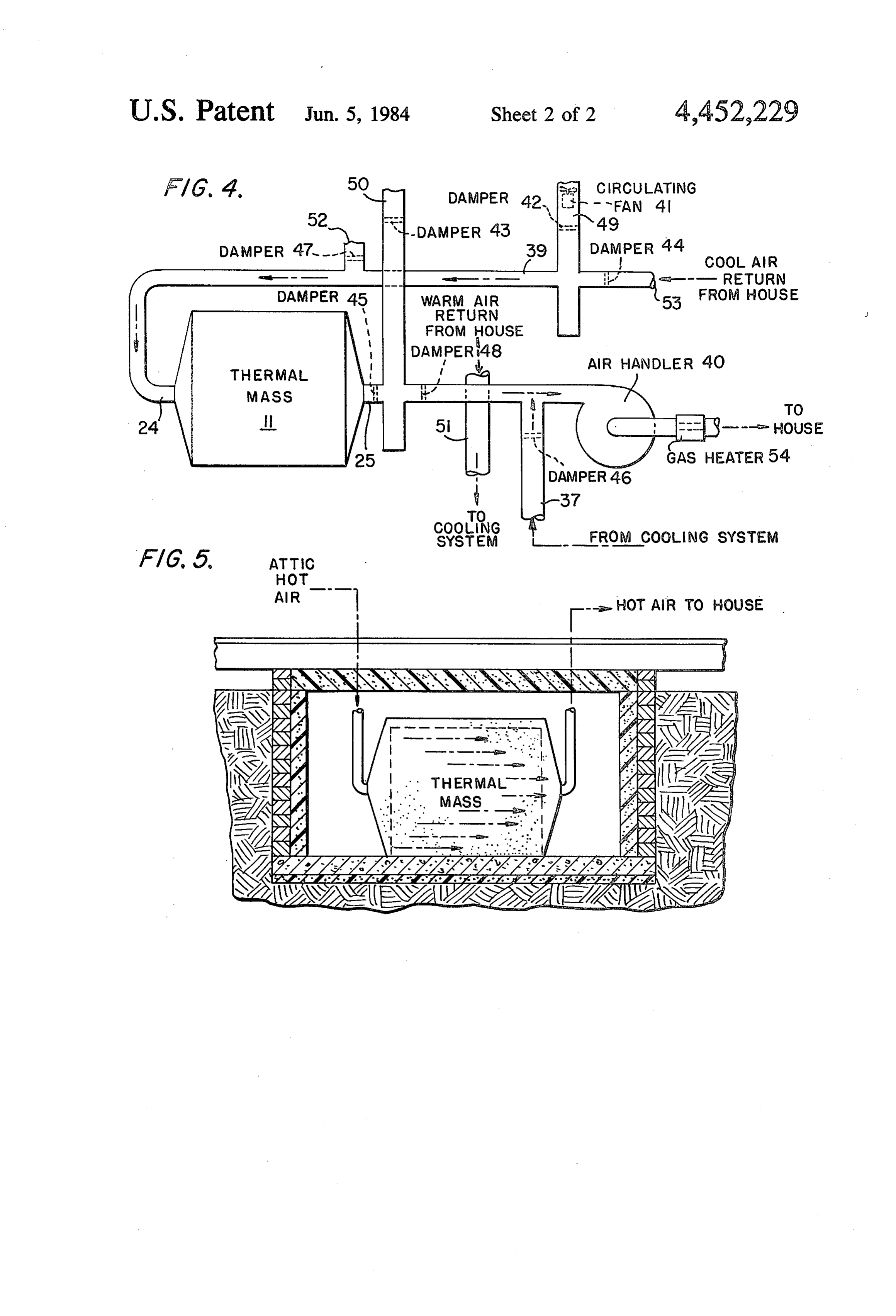
the thermal mass are closed and air is pulled by the air FIG. 4 is a schematic flow view of the circulation handler from the cooling walls to the area to be cooled means showing the arrangement of the metal ducts, and back through the cooling walls which achieve cool pipes, air handler, circulating fan, gas heater and damp temperatures from the surrounding earth whether the CS.
walls be bermed or embedded in the earth. During 35 FIG. 5 is a schematic sectional view showing the summer months, the thermal mass can also be used as a general arrangement of the below-ground version of a backup cool air storage unit by closing the dampers to thermal heat storage and cooling system constructed in the solar energy collector, opening the dampers to the accordance with the present invention. Details of the thermal mass and circulating the cool night air from the storage means and cooling means, not shown, are ex outside. to and through the thermal mass which can actly the same as shown in FIGS. 2 and 3, except the absorb and store cool air as an alternative to heat. adjacent earth surrounding the embedded room on On a sunny day the area to be heated can be serviced three sides substitutes for the berming. directly from the solar energy collector by closing the DETAILED DESCRIPTION OF THE dampers connecting the thermal mass to the system 45 PREFERRED EMBODIMENT OF THE thereby effectively bypassing the storage means. INVENTION
OBJECTIVES OF THE INVENTION The improved thermal heat storage and cooling sys The objectives of the present invention are to provide tem is a self-contained, multi-functional system for uti an improved thermal heat storage and cooling system 50 earth insolar lizing energy and the cooling properties of the a versatile, economic manner. Using ready which is: available materials such as earth, hollow cement block, (1) capable of manual or fully automatic operation; plastic sheeting, sand and wood, the system is inexpen (2) constructed of readily available, low cost materi sive to construct and maintain and is designed for maxi als, thus making it less expensive to build than systems mum energy savings within the limits of the materials. known in the prior art designed to perform the same 55 Throughout the following detailed description of the function; present invention like reference numerals are used to (3) self-contained so that heat storage and generation denote like components disclosed in the accompanying of cool air can be embodied in the same system and drawings, FIGS. 1-5.
could be installed without structural modification of the As shown in FIG. 1, the above-ground version of the structure to be heated or cooled; 60 present invention can be installed external to, but at (4) versatile, in that the heat storage and cool air tached on any side of the area to be heated, such as generation means are independent and the system can house 10. Storage means, which is thermal mass 11 be used as an exterior installation, located on any side, shown in detail in FIG. 2, is a superinsulated cube of for heating and cooling structures with no basement or hollow cement blocks, exemplified at numeral 12, as can be used as an interior installation utilizing the earth 65 sembled on a superinsulated concrete slab 13. Each of beneath such structures; said hollow cement blocks 12 has been positioned so (5) easy to control to minimize loss of energy and that their apertures, exemplified at numeral 14, commu nicate with one another so as to form a series of horizon provide uniform flow of warm or cool air;
Page 6scan →
S 6 tal passageways, exemplified at numeral 15, for air walls 19 and the single interior cooling wall 26 when air through the interior of thermal mass 11. Although not is pulled through by the circulation means. The interior shown in FIG. 2, alternate horizontal passages verti surface of exterior cooling walls 19 and interior cooling cally or laterally could be filled with cement or sand to wall 26 are waterproofed to prevent moisture from increase the effective mass of said cube. Preferably said entering the area where thermal mass 11 is located. hollow cement blocks 12 would contain a magnesium Additional cooling effect is gained from the earth by additive to increase the conductance of said blocks. routing the cool air from cooling wall output 35 The typical thermal heat source would be a conven through underground pipe 36 buried beneath the earth's tional solar energy collector 16 which could be located, surface 20 below bermal material 18 snaking around the facing South, on the roof of house 10 as shown in FIG. 10 three exterior cooling walls 19 and back to cold air duct 1, or located in the attic below or mounted indepen 37 which leads to house 10. Air to be cooled enters said dently atop the external enclosure means which is a cooling means from house 10 at cooling wall input 38 room 17 external to the area to be heated or cooled but located at the top course of hollow cement blocks 30 of attached thereto on any side and is bermed completely interior cooling wall 26.
on all exposed structural walls as shown in FIGS. 1-3. 15 The circulation means of the present invention, The berming material, such as earth, exemplified at shown as a flow diagram in FIG. 4, is a network com numeral 18, is placed against the outside of the three prised of metal ducts, exemplified at numeral 39, input exterior cooling walls, exemplified at numeral 19, from pipe 24 and output pipe 25, cooling wall input 38, cool the earth's surface, exemplified at numeral 20, up to the ing wall output 35, underground pipe 36, cold air duct top of each of said exterior cooling walls 19. Although 20 37, which interconnect solar energy collector 16 with not shown in attached drawings, a column of sand could thermal mass 11 and house 10. Also said network inter be inserted between berming material 18 and the outside connects exterior cooling walls 19, interior cooling wall of the three exterior cooling walls 19 to improve drain 26 and house 10. During the heating modes, air handler age. The berming material 18 is held in place by retain 40 is inserted, as a component of said network and circu ing walls 21 and covered for a short distance from the 25 lation means, between house 10 and thermal mass 11. roofline with protective plastic strips 22 which extend During the cooling modes, air handler 40 is inserted just below the surface of berming material 18 to keep between house 10 and exterior cooling walls 19 and water away from exterior cooling walls 19. Vegetation interior cooling wall 26. Circulating fan 41, as a compo is shown planted atop berming material 18 to stabilize nent of said network and circulation means, circulates the ground temperature of said berming material 18. 30 warm air between thermal mass 11 and solar energy Access to room 7 from house 10 is through door 23. collector 16 during the recharging mode of the present Although not shown in the attached drawings, concrete invention. Dampers 42, 43, 44, 45, 46, 47 and 48 are slab 13 could be further insulated by including sawdust additional components of said network and circulation in the concrete mixture forming said slab. Thermal mass means, as is gas heater 54, an auxillary source of heat. 11 is interconnected with the circulation means, which 35 During Mode 1 when it is desired to heat house 10 on is detailed in FIG. 5, by input pipe 24 and output pipe sunny days, dampers 43,46 and 47 are closed and damp 25. ers 42, 44, 45 and 48 are opened. Air handler 40 draws Interior cooling wall 26 frames door 23 and is adja warm air from solar energy collector 16 down through cent to outside wall 27 of house 10. A column of sand 28 input pipe 24, through thermal mass 11 and out-through further insulates room 17 from house 10 and provides output pipe 25 to house 10.
drainage for condensation. Roof 29 of room 17 is con During Mode 2 when it is desired to heat house 10 on structed of conventional roof rafters filled in between cloudy days or evenings, dampers 42, 43, 46 and 47 are with insulating material. Exterior cooling walls 19 and closed, dampers 44, 45 and 48 are opened and air han interior cooling wall 26 serve the dual function of struc dler 40 recirculates warm air stored in thermal mass 11 tural support for room 17 and as the cooling means of 45 by drawing air from house 10, through duct 39, down the present invention. This cooling means, which is through input pipe 24, through thermal mass 11 and out interconnected with the circulation means, is three in through output pipe 25 to house 10, then back to ther terconnecting exterior cooling walls 19 and one interior mal mass 11.
cooling wall 26 each said wall comprised of staggered During Mode 3 when it is desired to rechargethermal hollow cement blocks, exemplified at numeral 30, 50 mass 11 on sunny days and house 10 requires no heat, whose apertures, exemplified at numeral 31, are aligned dampers 42, 43 and 45 are opened, dampers 44, 46, 47 in this embodiment over one other so that cool air gen and 48 are closed and air handler 40 deactivated. Circu erated therein can move vertically up and down lation fan 41 is activated, recirculating warm air from through the column of hollow cement blocks 30 as solar energy collector 16 down through duct 49 shown best in FIG. 3. In this embodiment the top 55 through input pipe 24 and thermal mass 11, out through course, exemplified at numeral 32, and the bottom output pipe 25 and back up to solar energy collector 16 course, exemplified at numeral 33, of hollow cement through duct 50 which with duct 49 is a component of blocks 30 are adapted so as to have a single aperture, said network and said circulation means. exemplified at numeral 34, by removing the convential During Mode 4, when it is desired to heat house 10 on partition found between the two apertures 31 found in cloudy days or evenings, when there is no heat available the conventional hollow cement block 30. Top course in thermal mass 11, dampers 42, 43,46 and 47 are closed, 32 and bottom course 33, of hollow cement blocks 30, dampers 44, 45 and 48 are opened and air handler 40 having said single apertures 34, are then staggered one draws air from house 10, through 39, down through half block to the left or right so that cold air from one input pipe 24, through thermal 11, out through outpipe column of hollow cement blocks 30 can travel horizon 65 25 and through gas heater 54 to house 10. tally to the adjacent column of hollow cement blocks 30 warm During Mode 5 when it is desired to cool house 10 on thereby permitting continuous air movement through days or evenings, dampers 42, 43, 44, 45, 47 and the interior of the three interconnected exterior cooling 48 are closed and damper 46 is opened. Air handler 40 7 draws air from house 10 through duct 51 which is a pipe, and cold air duct, which said network inter component of said network and circulation means, to connects said solar energy collector, said storage cooling wall input 38, through interior cooling wall 26, means and said cooling means with said area to be and exterior cooling walls 19, out cooling wall output heated and cooled and with each other, and 35, through underground pipe 36, through cold air duct 5 a roof, filled with insulating material, which with said 37 to house 10, the area to be cooled. external enclosure means and said concrete slab During Mode 6, on a cool evening, when it is desired form an enclosure for said storage means and said to charge thermal mass 11 with cold night air from cooling means used to heat and cool air carried by outside of room 17, thus using thermal mass 11 as a said circulating means to and from said area to be backup cold storage unit, dampers 42, 43 and 46 are 10 heated and cooled.
closed, dampers 44, 45, 47 and 48 are opened. Upon 2. The improved thermal heat storage and cooling activation, air handler 40 pulls cold air from outside, system of claim 1 wherein berming material, such as through air input 52, which is a component of said net earth, is placed against the outside, and up to the top, of work and circulation means, through input pipe 24, each said thermal mass 11, and output pipe 25 to house 10. The air 15 3. The three interconnecting exterior cooling walls. improved thermal heat storage and cooling returns through cool air return 53, which is a compo system of claim 1 wherein said external enclosure means nent of said network and circulation means, and duct 39 to point of origin, thus cooling house 10 while at the issaidabove-ground, house to be installed external to, but attached to, heated and cooled, and wherein berm same time storing residual amounts of cool air in ther ing material, such as earth, mal mass 11 for later utilization using Mode 2. 20 and up to the top, of eachissaid placed against the outside, three interconnecting
During Mode 7, when it is desired to heat house 10 exterior cooling walls.
directly from solar energy collector 16, dampers 42, 43, 4. The improved thermal heat storage and cooling 44 and 48 are opened, and dampers 45, 46 and 47 are system of claim 1 wherein said external enclosure means closed. Upon activation, air handler 40 pulls warm air is below-ground, from solar energy collector 16, down through duct 50 25 said single interiorinstalled cooling external to, but attached by wall to, said house to be to the area to be heated, house 10. The air is returned heated and cooled, and wherein said three interconnect through cool air return 53 and duct 49 to solar energy ing exterior cooling walls are surrounded to the top of collector 16, thus completing the cycle. each said wall by the adjacent earth. I claim:
1. In combination with a house or other structure, a 30 5. The improved thermal heat storage and cooling system of claim whereby air from within said house is solar energy collector for heating air, and an auxiliary circulated gas heater for heating air, the improved thermal heat heat energythrough said cooling means, transferring the of said air to said three interconnecting storage and cooling system comprising:
storage means, for storing heat or cold, having a exterior cooling walls and said single interior cooling superinsulated cube of hollow cement blocks as- 35 wall, to cool said air and whereby said cold air is then recirculated to said house.
sembled on a concrete slab, each of said hollow 6. The improved thermal heat storage and cooling cement blocks being positioned so that their aper tures communicate with one another so as to form system of claim 1 wherein said storage means is charged a series of horizontal passageways for air through with cold night air from outside for the subsequent the interior of said hollow cement blocks, and 40 generation of cool air by circulation of air from said external enclosure means, external to the area to be house through said storage means and back to said heated or cooled but attached thereto on any side, house.
forming a room to enclose said storage means, and 7. The improved thermal heat storage and cooling cooling means comprising three interconnecting exte system of claim 1 wherein said superinsulated cube of rior cooling walls and a single interior cooling wall 45 hollow cement blocks is constructed from conventional each said wall waterproofed on the interior surface hollow cement blocks cast from cement containing a and comprised of staggered hollow cement blocks magnesium additive to improve the thermal conductiv whose apertures are aligned over one another so ity of said storage means.
that cool air generated therein can move vertically 8. Cooling means comprising three interconnecting up and down through the column of hollow ce- 50 exterior cooling walls and a single interior cooling wall, ment blocks, the top course and bottom course of each said wall waterproofed on the interior surface and said hollow cement blocks adapted so as to have a comprised of staggered hollow cement blocks, whose single aperture and staggered so that cold air from apertures are aligned over one another so that cool air one column of hollow cement blocks can travel generated therein can move vertically up and down horizontally to the adjacent column of hollow ce- 55 through the column of hollow cement blocks, the top ment blocks, permitting continuous air movement course and bottom course of said hollow cement blocks through the interior of said three interconnecting adapted so as to have a single aperture and staggered so exterior cooling walls and said single interior cool that cold air from one column of hollow cement blocks ing wall when air is pulled through by circulation can travel horizontally to the adjacent column of hol means, and 60 low cement blocks, permitting continuous air move circulation means, to carry air to and from said area ment through the interior of said three interconnecting to be heated and cooled, having a network com exterior cooling walls and said single interior cooling prised of metal ducts, input pipe, output pipe, cool wall when air is pulled through by circulation means. ing wall input, cooling wall output, underground k . . s. sk
Provenance
- Collection
- Patents citing this work
- Pages
- 7
- Method
- pdftotext (the PDF's own text layer) + pdftoppm 300dpi page scans
- Patent office record
- patents.google.com →
- Source
- Google Patents citing-documents table
- Assignee
- Kim Powers
- Published
- 1984-06-05
- Transcribed from
- patentimages.storage.googleapis.com →