

patent · US4463799A
Heat storage medium for latent heat thermal energy storage unit
7 August 1984
Text
Page 1bibliographic recordscan →
United States Patent (19)
Takahashi et al.
(54) HEAT STORAGEMEDIUM FOR LATENT
HEAT THERMAL ENERGY STORAGE UNIT
75 Inventors: Yoshio Takahashi, Urawa; Takeo
Ozawa, Ibaraki; Ryuji Sakamoto,
Kashiwa; Katsuhiko Kanari;
Masayuki Kamimoto, both of Ibaraki, all of Japan Assignee: Agency of Industrial Science
Technology, Ministry of International
Trade & Industry, Tokyo, Japan
30 Foreign Application Priority Data
Oct. 29, 1980 JP Japan ................................ 55-151845 Int. Cl. .............................................. F28D 21/00 52 U.S. Cl. ........................................ 165/10; 264/22;
58 Field of Search ...................... 165/10; 264/22, 83;
4,063,546 12/1977 Schmid et al. .................... 165/10 X 4,182,398 1/1980 Salyer et al. ............................ 165/1
Primary Examiner-Albert W. Davis, Jr.
Attorney, Agent, or Firm-Oblon, Fisher, Spivak,
McClelland & Maier
A heat storage medium for use in a latent heat TES unit is obtained by treating a crystalline polyolefin with ion plasma thereby crosslinking it only in the surface re gion.
3 Claims, 4 Drawing Figures
Drawings
Page 2drawing sheetscan →
Page 3scan →
method which effects form-stability by grafting the
HEAT STORAGE MEDIUM FOR LATENT HEAT surface of polyolefins with a silane is not economical THERMAL ENERGY STORAGE UNIT because it requires large equipment and complicates the production process.
Summary of the invention
This invention relates to a heat storage medium for use in a latent heat thermal energy storage unit. An object of this invention is to provide a heat stor The qualities which thermal energy storage units in age medium for a latent heat TES unit, which is made of general are required to posssess are large capacities for a crystalline polyolefin so treated that it retains the storage of heat, low price, long service life, and good 10 particular qualities which make it suitable for storage of heat transfer characteristics. Broadly thermal energy latent heat undegraded and also retains its original form storage units (hereinafter referred to as "TES units”) unaffected by fusion or flow even when it is held in are divided into sensible heat TES units which make use direct contact with a heat transfer medium. of advantageous heat capacities and latent heat TES To accomplish the object described above according units which make use of latent heat as in fusion and 15 to the present invention, there is provided a heat storage solidification of substances or transition of crystals. In medium which is obtained by forming crystalline poly the former heat TES units, the capacities are deter ethylene in a required shape such as pellets, rods, or mined by the temperature and heat capacity of the heat films and treating the formed polyethylene with ion storage media used therein. To increase capacities, 20 plasma. When the formed crystalline polyolefin is therefore, the TES units are required to either heighten treated with the ion plasma as described above, cross the temperature of heat storage media or increase the linking occurs only in the surface region of the formed volume of heat storage media to be used. In the latter crystalline polyolefin. Consequently, the heat storage heat TES units which make use of the heat of fusion of crystalline substances, since the heat storage media on medium ternal is allowed to retain its form unaffected by ex impacts such as of fusion or flow even when it is fusion assume a liquid state, they require perfect separa held in direct contact with a heat transfer medium. In tion between heat transfer media and heat storage media used therein and inevitably complicate their structures. addition, it retains intact the desirable heat conduction If a heat storage medium to be used in a latent heat TES shape. attributable to its particular pellet, rod or film properties unit is processed so that it retains its original form even when it is softened during the fusion, then this heat 30 willThe other objects and characteristics of this invention storage medium can be kept in direct contact with the invention to apparent become from the further disclosure of the be made below with reference to the ac heat transfer medium. The use of this heat storage me companying drawings.
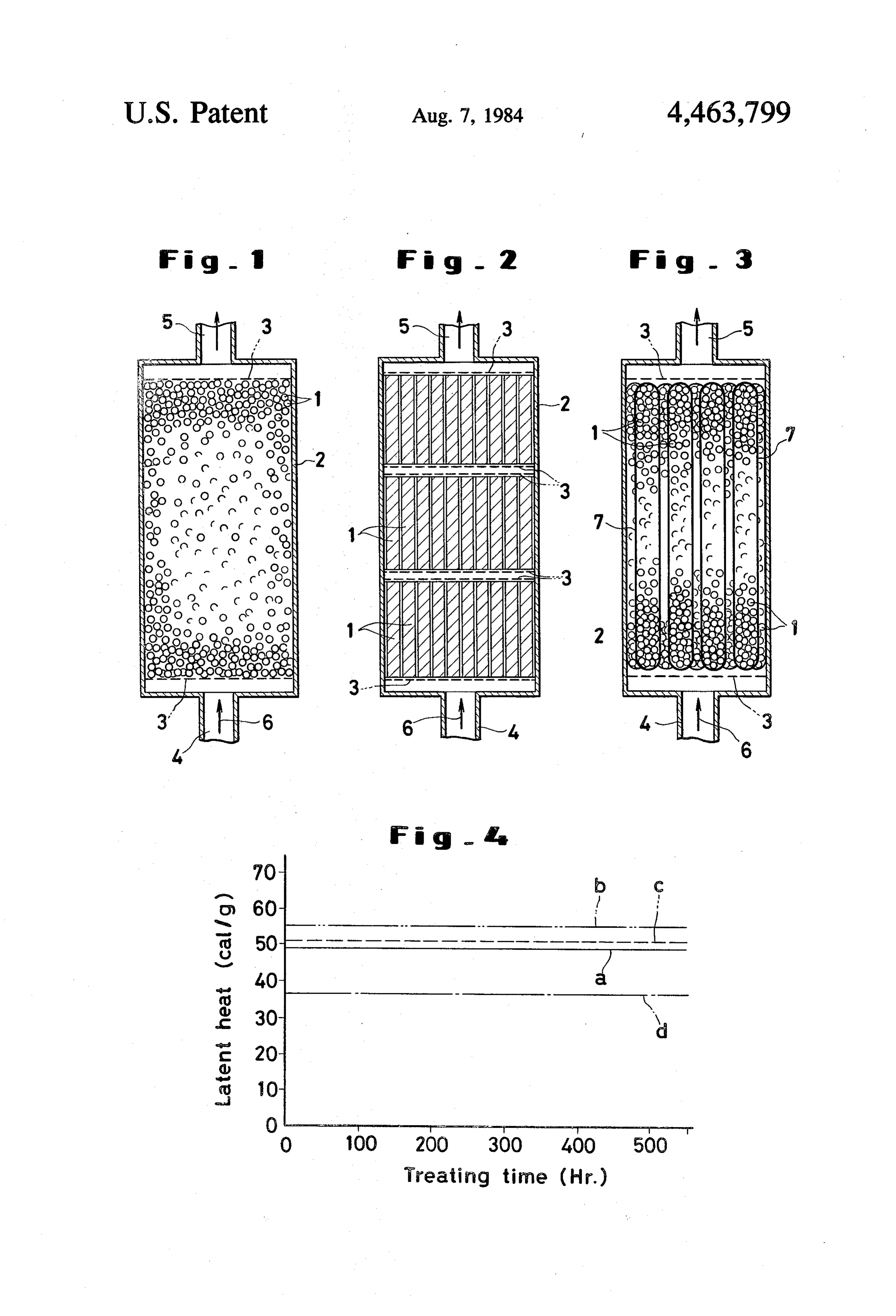
dium, therefore, simplifies the TES unit's structure and enhances the heat transfer characteristics. BRIEF DESCRIPTION OF THE DRAWING Crystalline polyolefins are inexpensive, possess high 35 thermal stability, produce no corrosive actions upon FIG. 1 is a longitudinal cross section illustrating the containers and other vessels, exhibit no toxicity, and with first embodiment of the latent heat TES unit packed generate relatively large latent heat. These are excellent the heat storage medium of the present invention. qualities for a heat storage medium in a latent heat TES FIG. 2 is a longitudinal cross section illustrating the unit. Nevertheless, they have a disadvantage that, even 40 second embodiment of the latent heat TES unit packed in a fused state, they are so viscous as to defy flowing with the heat storage medium of the present invention. motion by convection or agitation unlike ordinary liq FIG. 3 is a longitudinal cross section illustrating the uids and further that, because of their low thermal con third embodiment of the latent heat TES unit packed ductivity, they cannot be effectively used in the form of with the heat storage medium of the present invention. large blocks. To overcome these disadvantages, there 45 FIG. 4 is a graph showing the relation between the have been proposed a method which uses such crystal heating time and the latent heat obtained of the heat line polyolefins as molded in the form of pellets, rods or storage medium of the present invention. films and crosslinked so that they will retain their origi DESCRIPTION OF PREFERRED nal forms even when they are exposed to contact with EMBODIMENTS a heat transfer medium, and a method which uses the 50 polyolefins as enclosed with capsules. As materials for the heat storage medium in the latent As for the aforementioned methods, there are meth heat TES unit, polyolefins possess excellent qualities ods disclosed in U.S. Pat. No. 4,182,398 which are indi such as low price, high safety, and relatively large latent cated below: heat. When a heat storage medium made of a polyolefin (i) Crosslinking effected with a crosslinking agent 55 in particulate form is fused, the individual particles of such as a peroxide incorporated in polyolefins. the medium mutually adhere and induce degradation of (ii) Crosslinking effected by irradiation with electron heat transfer characteristics due to low heat transfer beams. area. There have been proposed methods for precluding (iii) Using graft-polymerization to cover the surface the mutual adhesion of the individual particles of the of polyolefins with a silane which acts as a capsule. 60 heat storage medium during its fusion by grafting with The polyolefins, when crosslinked with a crosslinking a silane or by crosslinking the crystalline polyolefin or a agent incorporated therein, suffer degradation of the thermoplastic resin, or by irradiation with electron particular qualities which make them suitable for stor beams, for example. These efforts, however, tend to age of latent heat. When the crosslinking of polyolefins impair the desirable qualities of polyolefins as materials is effected by irradiating polyolefins with electron 65 for the heat storage medium in the latent heat TES unit. beams, the polyolefins are crosslinked to the interior The inventors made various studies and experiments and are apt to suffer degradation of the qualities which in search for a crystalline polyolefin capable of retaining make them suitable for storage of latent heat. The its advantageous qualities for the storage of latent heat 4 intact and defying flow and mutual adhesion during thermal energy storage tank. The interior space defined fusion. They have consequently found that when a crys by the wall of the tank and the two metal nets is packed talline polyolefin formed in a required shape such as with a heat storage medium 1 prepared by treating a pellets, films or rods is treated with ion plasma, the pelletized polyolefin with ion plasma. In the latent heat polyolefin in the particulate form is crosslinked only in TES unit constructed as described above, storage of the surface region thereof so that the heat storage me heat is effected by passing a heat transfer medium 6 at an dium, on contact with the heat transfer medium, is fused elevated temperature through the inlet 4 into direct only inside the individual polyolefin pieces and, there contact with the heat storage medium 1 thereby melting fore, is prevented from mutual adhesion and allowed to the interior of the particles of the heat storage medium retain the original advantageous qualities of the polyole 10 1. The heat transfer medium 6 which has completed fin virtually intact. This invention has been accom heat exchange and has consequently been cooled to a plished on this knowledge. lower temperature is discharged through the outlet 5. Theoretically, any polyolefin can be used for the When the packing density of the heat storage medium in purpose of this invention so far as it is crystalline. From the tank is lowered, the medium is fluidized by the flow the practical point of view, however, crystalline poly 5 of the heat transfer medium and, in the fluidized state, is ethylene proves advantageous over all the other poly allowed to exchange heat with the heat transfer me olefins. The crystalline polyolefin is formed by a known dium.
method in any desired shape such as pellets, rods, or Since the polyolefin is oxidized and consequently films to suit the particular structure of the latent heat embrittled in the presence of oxygen, the heat transfer TES unit to be used. When crystalline polyethylene is 20 medium must be free from oxygen. Thus, an inert gas adopted, the heat storage medium is desirably molded in such as argon or nitrogen gas can be used advanta the shape of pellets of a diameter roughly in the range of geously as the heat transfer medium. Optionally, a fiq 0.5 to 3 mm, rods of a diameter roughly in the range of uid heat transfer medium may be used on condition that 2 to 10 mm, or films of a thickness roughly in the range it is prevented from exposure to air. of 0.3 to 1.0 mm. 25 FIG. 2 illustrates a latent heat TES unit which is After the crystalline polyolefin has been formed in packed with a multiplicity of rods of the heat storage the required shape as described above, it is treated with medium of this invention. When the heat storage me ion plasma. The plasma reactor to be used for this treat dium 1 which is in the shape of rods exchanges heat ment can be of any of the known types using any of with the heat transfer medium 6, it is wholly softened as various power sources such as high frequency waves, 30 its interior is fused. If the heat storage medium is in the micro-waves, direct current, alternating current, etc. shape of rods of a large length, the rods wholly softened The treating time is suitably fixed, depending on the as described above are no longer able to retain their structure of the reactor, the type of power source, the straight shape but are bent out of shape. Consequently, inner pressure of the reactor, the flow volume of gas, the heat transfer medium finds its way through particu the shape of the crystalline polyolefin particles, etc. If 35 lar paths formed between bent rods within the thermal the treating time is more or less greater than is actually energy storage tank interior and tends to depart from required, since the collision cross-section of molecular the outlet 5 before it has amply exchanged heat with the ions or atomic ions colliding with the polyolefin parti heat storage medium. To preclude this trouble, there cles is large enough, the crosslinking reaction is allowed fore, a multiplicity of metal nets 3 are spaced in the to occur only within the surface region of the polyolefin 40 direction of the flow of the heat transfer medium inside particles. Thus, the polyolefin retains its crystallinity the thermal energy storage tank 2 so as to ensure effec (latent heat) substantially intact. Volume treatment of tive contact beteen the heat transfer medium and the the polyolefin with ion plasma can be obtained by caus heat storage medium.
ing the polyolefin already formed in the required shape FIG. 3 illustrates another manner in which the heat to be retained for a required length of time in the cur 45 storage medium of the present invention is put to use. rent of ion plasma. In this manner, the treatment can be The latent heat TES unit in this embodiment is formed carried out continuously. by preparing a multiplicity of capsules 7 each made of a When the crystalline polyolefin particles which have metal such as iron, aluminum, or stainless steel and been subjected to the ion plasma treatment as described packed airtightly with the heat storage medium 1 of a above are exposed to a heat transfer medium at an ele 50 suitable shape in conjunction with a liquid heat transfer vated temperature of about 150° C., they melt by ab medium of low vapor pressure such as, for example, sorbing the latent heat and become fluid in their inner silicone oil or ethylene glycol, and encasing these cap region but are not rendered fluid on their surface to the sules within a thermal energy storage tank 2. In this extent of inducing mutual adhesion of adjacent polyole embodiment, any gaseous or liquid substance which is fin particles. As the temperature falls, the polyolefin 55 incapable of corroding the TES unit can be used as the particles resume their original shape. heat transfer medium 6 serving to effect heat exchange The crystalline polyolefin particles which have been even if it is capable of affecting the inherent properties treated with ion plasma as described above are placed in of the heat storage medium. In this respect, the present the latent heat TES unit and left in contact with the heat embodiment proves economical. When iron, stainless transfer medium. 60 steel or other similar metal is adopted as the material for FIG. 1 illustrates one embodiment of the latent heat the capsules, the capsules can be safely exposed without TES unit usable with the heat storage medium of this any cnange in appearance to the heat transfer medium invention. It comprises a thermal energy storage tank 2, even at such a high temperature that the interior of the an inlet 4 and an outlet 5 both provided in the thermal heat storage medium contained therein is fused. energy storage tank and adapted for permitting flow of 65 Release of the stored latent heat from the TES unit is a heat transfer medium through the interior of the ther accomplished by introducing a medium desired to be mal energy storage tank, and metal nets 3 provided one heated through the inlet 4 into the thermal energy stor each in the upper and lower parts of the interior of the age tank 2 in the same way as in the storage of heat 5 thereby allowing the medium to absorb the heat of oil heated to 150° C. While those of Specimen Nos. 1, 2 fusion (latent heat) from the heat storage medium 1 and and 3 were found to show no change and resume their thereafter discharging the medium through the outlet 5. original form after removel of heat. The polyethylene Among many constructions of the latent heat TES pellets of Comparative specimen fused to one another in unit in which the heat storage medium of the present 5 the hot silicone oil and remained in the fused state even invention can be effectively used, three typical con after removal of heat. w structions have been cited above by way of illustration. Then, the polyethylene pellets of Specimen No. 2 When the heat storage medium is in the shape of films, were placed in an aluminum container with silicon oil for example, the latent heat TES unit is required to be in a construction which befits the particular shape of the 10 (made under by Shinetsu Chemical Co., Japan and marketed designation of KF-54) sealed therein, set in posi heat storage medium. tion within a constant temperature bath, and tested for As described in detail above, the present invention possible loss of latent heat and possible degradation of prepares the heat storage medium by treating separate material.
pieces of a crystalline polyolefin with ion plasma containerFor the purpose of comparison, an aluminum having untreated polyethylene pellets and thereby crosslinking the crystalline polyolefin in the 15 silicon oil sealed therein, an aluminum container having surface region of the separate pieces thereof. Conse untreated polyethylene pellets and alkyl diphenyl (made quently, when this heat storage medium is exposed to by Yawata Chemical Co., Japan and marketed under the heat transfer medium at an elevated temperature, it designation of Therm S 600) sealed therein, and an is softened but is left unfused with the exception of the aluminum interior thereof by the action of the heat. When it is 20 pellets treated with electron beamstherein container having sealed polyethylene formed in the shape of pellets, rods, or films, the sepa same time in the constant temperaturewere placed at the bath. These spec rate pieces thereof do not adhere to one another. When imens were left standing in the bath for 550 hours. At the separate pieces of the heat storage medium are sur the end of the standing, the specimens were taken out of rounded by the heat transfer medium, they are pre the bath and tested for latent heat. The results were as vented from contact with the ambient air and conse 25 shown in FIG. 4. In the graph of FIG. 4, the character quently from the otherwise possible oxidative degrada istic curve "a" represents the results of the polyethylene tion and are enabled to offer stable service for a long pellets produced by the method of this invention, the
Now, the present invention will be described with characteristic curve "b' those of the specimen includ reference to examples. It should be noted, however, 30 ing both polyethylene pellets and silicone oil, the char that this invention is not limited to these examples. acteristic curve "c' those of the specimen including both polyethylene pellets and alkyl diphenyl, and the
EXAMPLE 1. characteristic curve "d" those of the polyethylene pel In a plasma C.V.D. (chemical vapor deposition) ap lets treated by irradiation with electron beam. paratus having a quartz reaction tube 150 mm in diame 35 It is seen from FIG. 4 that no thermal degradation ter 225 mm in height provided 100 mm thereabove with was obtained in any of the specimens involved. The two semicircular electrodes, 5g of crystalline polyeth latent heat of the polyethylene pellets of the present ylene pellets about 1 mm in diameter were placed in a invention was far higher than that of the polyethylene specimen receptacle. The container of the apparatus pellets treated with electron beam or that of the un was evacuated to 103 Torr and, thereafter, argon gas treated polyethylene pellets (43.3 cal/g) and was nearly was fed to the container at a rate of 300 ml/min until the equal to that of the specimen containing both polyethyl inner pressure of the container rose to about 0.25 Torr. ene pellets and alkyl diphenyl.
Then, an electric current of 0.24A and 1.5 kV was EXAMPLE 2 applied to the anode to cause generation of argon ions, with the pellets exposed to the argon ions for a varying 45 Polyethylene pellets were treated under the same contact time (20, 30, and 40 minutes). At the end of the conditions as those of Example 1, except that the volt treatment, the specimen was tested for latent heat and age and current at the anode were changed to 2.5 kV melting point. The results were as shown in the follow and 0.38A. Consequently, there were obtained polyeth ing Table. For the purpose of comparison, the latent ylene pellets which possessed practically the same prop heat and melting point obtained of the same polyethyl 50 erties as those of Specimen No. 3 of Example 1. When ene pellets in their untreated form are also shown in the polyethylene pellets were treated by following the pro Table. The term "melting point" as used herein means cedure described above, except that the current at the the temperature at which a given polyethylene sample anode was changed to 0.37A and the treating time to 10 was fused to a substantially liquid state retaining virtu minutes, the resultant polyethylene pellets on contact ally no crystalline phase. 55 with silicone oil at 150 C, were found to curl slightly. TABLE Despite the curling, these pellets could be used effec Treating time Latent heat Melting point tively as a latent heat storage medium without any trou Specimen No. (min) (Cal/g) (°C) ble.
Example 3
3 40 46.8 135,8 In the same apparatus as used in Example 1, a poly Comparative 43.3 135.2 ethylene film 0.5 mm in thickness and 20 mmx20mm in specimen area was placed in a container. The container was evac uated to 103 Torr. Then, argon gas was fed at a flow
The polyethylene pellets of Specimen Nos. 1, 2, and 3 65 rate of 200 ml/min into the container and an electric which had been treated with ion plasma and the poly current of 1.5 kV and 0.27A was fed to the anode to ethylene pellets of Comparative specimen which had cause generation of argon ions, with the polyethylene not been treated were brought into contact with silicon film exposed to the ion plasma for 30 minutes. Thereaf 6 ter, the polyethylene film was turned upside down and contact with silicon oil at 150 C., it was found to shrink was exposed similarly to the ion plasma for 30 minutes. and undergo adhesion.
The resultant film was found to have latent heat of 49.3 What is claimed is:
cal/g (206.5J/g) and a melting point of 135.2° C. The 5 1. A heat storage medium for a latent heat TES unit, same polyethylene film as used above was treated under obtained by treating a crystalline polyolefin with ion the same conditions described above, except that the plasma thereby crosslinking it only in the surface region thereof.
flow rate of argon gas was changed to 300 ml/min and 2. The heat storage medium according to claim 1. the current at the anode was changed to 0.31 A. The wherein the crystalline polyolefin is crystalline polyeth resultant polyethylene film was found to have latent O ylene.
heat of 48.2 cal/g (201.1 J/g) and a melting point of 135° 3. The heat storage medium according to claim 1 or C. When the films were exposed to silicone oil at 150 claim 2, wherein the crystalline polyolefin is formed in C., absolutely no adhesion was observed between the a required shape and thereafter treated with ion plasma. films. When untreated polyethylene film was placed in s :
Provenance
- Collection
- Patents citing this work
- Pages
- 6
- Method
- pdftotext (the PDF's own text layer) + pdftoppm 300dpi page scans
- Patent office record
- patents.google.com →
- Source
- Google Patents citing-documents table
- Assignee
- Agency Of Industrial Science Technology, Ministry Of International Trade & Industry
- Published
- 1984-08-07
- Transcribed from
- patentimages.storage.googleapis.com →