

patent · US4468568A
Generating power from the ocean utilizing the thermal properties of magnetic material
28 August 1984
Text
Page 1bibliographic recordscan →
United States Patent (19)
Carr, Jr. et al.
54 GENERATING POWER FROM THE OCEAN
UTILIZING THE THERMAL PROPERTIES
OF MAGNETIC MATERAL
76 Inventors: Walter J. Carr, Jr., 1460 Jefferson
Heights; Robert C. Miller, 1746
Williamsburg, both of Pittsburgh, Pa.
Int. Cl. ................................................ F03G 7/04 52 U.S. C. ..................................... 290/1 R; 60/398;
58 Field of Search ................. 290/1 R; 415/DIG. 2;
2,549,464 4/1951 Hartley ............................... 390/1 R 3,126,492 3/1964 Swoboda ... - - - - 310/306
3,316,415 4/1967 Taylor ....... ... 310/306 3,743,866 7/1973 Pire ........... ... 310/306 4,064,409 12/1977 Redman ........ ... 310/306 4,210,819 7/1980 Wittig et al... ... 290/. R 4,230,963 10/1980 Kurpanek ........................... 30/306 Primary Examiner-J. V. Truhe
Assistant Examiner-A. Evans
Attorney, Agent, or Firn-Donald M. Boles
A power generation system is taught utilizing a ferro magnetic material contained in a tape and rotatably disposed in a triangular configuration around a series of pulleys. The entire system is under water in the ocean so as to utilize the temperature differentials available be tween just below the surface of the ocean and approxi mately 100 meters below. The tape which is ferromag netic passes through superconducting coils having par allel fields and thereby providing a very large magnetic field. The lower portion of the ferromagnetic tape, which is cooled by the ocean, experiences greater mag netization than the upper warmer portions of the mag netic tape. The lower portion of the tape experiencing greater magnetization is pulled up into the magnetic field and thereby causes movement of the tape. As the tape moves upward it is warmed by the ocean currents with the result that a lower portion of the tape now experiences the greater magnetization. This therefore causes continual movement. Attached to one of the pulleys is a drive belt arrangement which in turn is connected to a generator thereby causing the generator to turn and generate electricity upon movement of the magnetic tape.
12 Claims, 3 Drawing Figures
Drawings
Page 2drawing sheetscan →
Page 3scan →
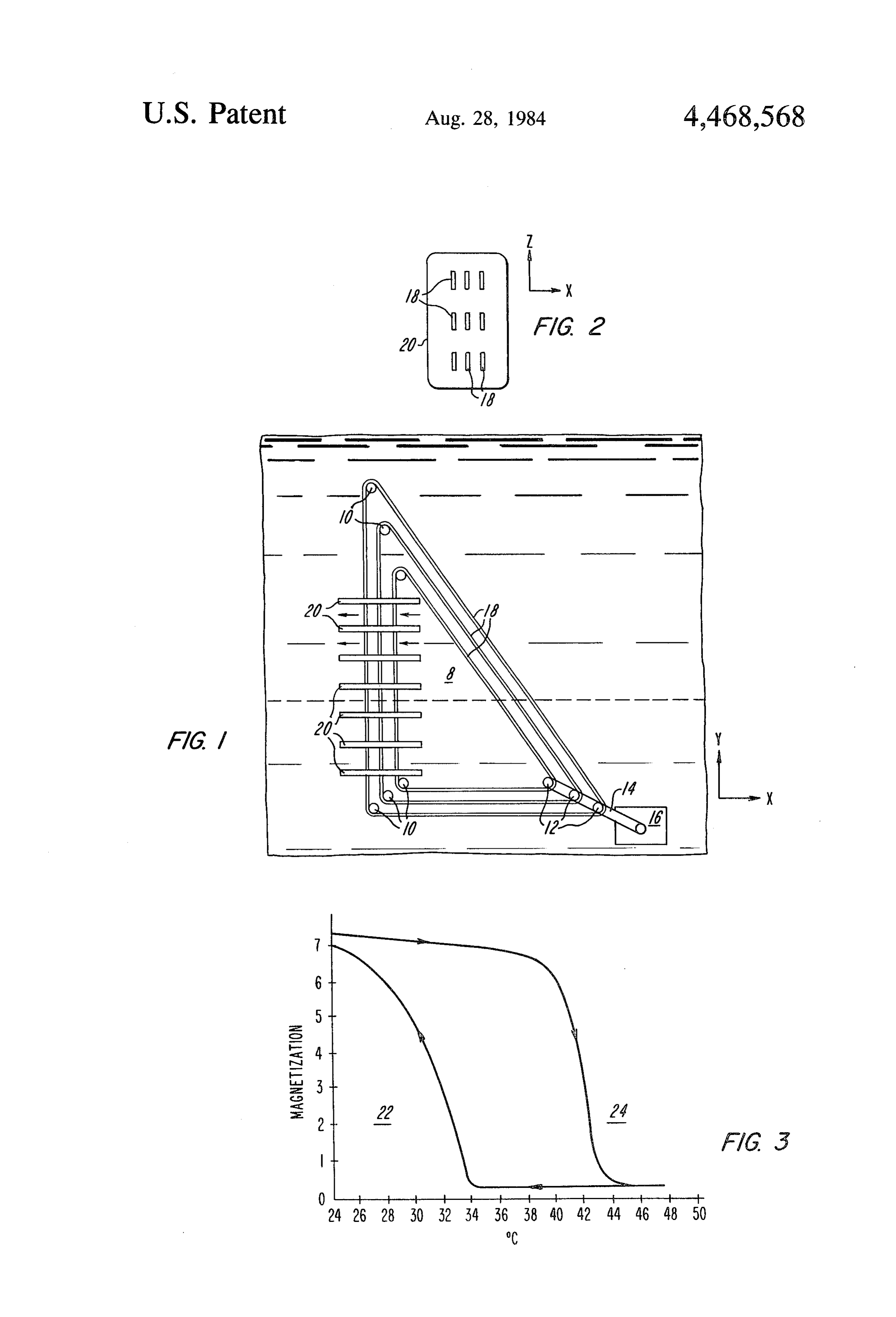
GENERATING POWER FROM THE OCEAN BRIEF DESCRIPTION OF THE DRAWINGS UTILIZING THE THERMAL PROPERTIES OF Reference is now made to the description of the pre MAGNETIC MATERAL ferred embodiment, illustrated in the accompanying drawings, in which:
The invention described herein may be made, used or magnetic FIG. 1 is a diagrammatic representation of a ferro sold by Westinghouse Electric Corporation, Pittsburgh, tape passing through superconducting elec PA on a royalty free, non-exclusive basis. tromagnetic coils and circulating around a number of pulleys;
BACKGROUND OF THE INVENTION 10 FIG. 2 is a partial sectional view taken through A-A This invention relates, generally, to power generation of FIG. 1 showing additional sets of magnetic tapes; and and more paticularly to the utilization of ferromagnetic theFIG.ferromagnetic 3 is a magnetization versus temperature curve of material Manganese Arsenide materials to take advantage of temperature differentials present in the ocean for the purpose of generating 15 (MnAs), as it goes through a first order phase change. power. DESCRIPTION OF THE PREFERRED It is known that ferromagnetic materials exhibit dif EMBODIMENT ferent amounts of magnetization near their curie point Referring now to the drawings and in particular to or near a phase change. This phenomenon has generally FIG.
been investigated for the purpose of providing a means 20 tion in1 there is shown a diagram of the present inven the Y-X plane. The power generation system for conversion into more readily usable forms of en shown generally at 8 as seen in the present figure is ergy. Such an approach may be found in U.S. Pat. No. positioned under the ocean surface so as to take advan 3,126,492 "Ferromagnetic Energy Devices' issued tage of the temperature differentials present at different Mar. 24, 1964 to T. J. Swoboda. Additionally, many depths of the ocean. It is well known that in portions of methods have been envisioned to utilize ferro to para 25 the ocean a near discontinuity of 6' C. occurs in the magnetic properties such as may be found in U.S. Pat. temperature at a depth of about 60 meters with respect No. 4,064,409 "Ferrofluidic Electrical Generator' is to the temperature near the surface. Below this point a sued Dec. 20, 1977 to Redman and U.S. Pat, No. further decrease of about 5 C. occurs over the next 40 3,743,866 "Rotary Curie Point Magnetic Engine' issued meters (100 meters of depth). Therefore a temperature July 3, 1973 to Pire. 30 gradient of approximately 11 C. is experienced when However, these systems have generally not been measuring temperatures between the ocean surface and economically feasible due to their overall low efficiency at approximately 100 meters below the ocean surface. as well as the requirement of manmade thermal energy Additionally it is well known that natural ocean cur such as found in U.S. Pat. No. 4,230,963 "HydroTher rents of approximately 50 to 100 centimeters per second mic Energy Converter" issued Oct. 28, 1980 to Kur 35 which aid in heat transfer are not uncommon. panek. Utilizing this temperature gradient is the power gen It is desirable to have a device which utilizes ferro eration system 8 found in FIG. 1. In the preferred em magnetic properties which utilize thermal conditions bodiment of the present invention there are nine ferro which are present in nature, thereby warranting the magnetic tapes (only there are shown in this view) overall cost of a system. It is also desirable to have a which travel in the direction shown, that is, clockwise device which has an overall efficiency greater than around the pulleys 10 and the drive shafts 12. Surround ing the vertical leg of the ferromagnetic tape 18 are previously experienced so as to produce an economi superconducting coils 20 which are used to produce a cally feasible device. Such a scheme is taught in the large magnetic field. The temperature distribution of present invention. the tape 18 tends to assume the temperature profile of Briefly stated, a device for using ferromagnetic mate 45 the ocean which thereby determines the magnetization rials to generate electrical energy is shown comprising of the tape 18 in that the magnetization of a ferromag a water reservoir having a temperature differential be netic material tween the surface thereof and at various depths thereat, ferromagnetic depends material upon temperature (FIG. 3). The in the preferred ebodiment of at least one ferromagnetic continuous loop tape rotat 50 the present invention is comprised ably disposed around a plurality of rotational devices nide (MnAs) having a few percentofofManganese phosphorus Arse for producing differing magnetization trations at differ added (although other materials may be utilized). The ent temperatures, a plurality of rotational devices dis lower portion of tape 18 will be cooler than the upper posed in the water reservoir and rotatably attached to portion of tape 18 due to the temperature differential of the ferromagnetic tape about the axis of each of the 55 the water as aided by ocean currents shown generally at rotational devices, the plurality of rotational devices 26. Through the use of the superconducting coils 20 a having at least a first rotating device disposed at a depth magnetic field is produced in a portion of the tape 18. in the reservoir which is different than that of a second Since, as mentioned earlier, the lower end of tape 18 rotational device, magnetic field mechanisms surround experiences a higher magnetization, tape 18 will be ing a first portion of the tape for magnetically attracting 60 pulled vertically upward into the maximum portion of a second portion of the tape wherein the second portion the field of the coils 20. However, as the tape 18 moves of the tape due to temperature differentials exhibits upward the temperature and therefore the magnetiza greater magnetization than the first portion of the tape tion at a point on the tape 18 that is being pulled into the thereby causing the tape to move and an electrical field 20 changes. This therefore causes tape 18 to con power generating device attached to at least one of the 65 tinuously move in a clockwise direction around the rotational devices for producing electrical energy upon pulleys 10 and thereby turning drive shaft 12. Attached the rotation of the ferromagnetic tape and hence the to the drive shafts 12 are drive belts 14 which turn with rotational device. the drive shaft 12 and in turn cause the shaft of a genera 4 tor shown generally at 16 to turn and thereby generate hysteresis curve shown in FIG. 3 to the left so that the electrical energy. AM occurs over the temperature range available in the The superconducting coils 20 in the preferred em OC.
bodiment of the present invention are separate coils, It is to be understood that many alternate embodi each coil having current circulating therein in the same ments of the present invention are possible without direction as the other coils. This therefore provides a departing from the spirit and scope of the present inven magnetic field for each superconducting coil 20 in the tion. For example, the drive belt 14 shown in FIG. 1 same direction. The strength of the magnetic field is could be comprised of gears or chains while the general extremely important in that the stronger the magnetic shape of the power generation system 8 could be gener field the larger the attraction of the ferromagnetic tapes 10 ally rectangular, square or any other suitable shape so as 18. This, will therefore affect the efficiency of the over to permit the necessary temperature changes above and all power generation system 8. Additionally in the pre below the curie point or phase change. Additionally a ferred embodiment of the present invention the wire comprising the superconducting coils 20 will be made different arrangement for generating power than the of a niobium-tin alloy (Nb3Sn) although it is to be un mission or 16 generator may be utilized such as including a trans intermediate prime mover to drive a genera derstood that different materials may be used without tor or any other suitable departing from the spirit and scope of the present inven utilize the movement of themeans tape or position so as to and thereby generate tion. It is to be understood however that the coils 20 may be connected in series or parallel combinations as electrical power. Further other magnetic materials such long as the field generated by each coil 20 is in the same 20 as Iron Nickel (FeNi), an alloy thereof or any other direction. Further, it is to be understood that the coils suitable material experiencing a ferromagnetic to para 20 may be spaced differently than that shown. Addition magnetic phase transition in the temperature range ally different numbers of coils 20 may be utilized or a available may be utilized. It is also to be understood that the present invention may be utilized in any bodygf single large coil could be used. Further, nonsupercon water experiencing a sufficient temperature differential. ducting coils may be utilized. 25
Referring now to FIG. 2 a partial sectional top view Therefore, in addition to the above-enumerated ad of FIG. 1 is shown. This view shows the power genera vantages, the disclosed invention produces a power tion system in the Z-X plane. Here it is clearly visible generation system which is cost effective, providing that the superconducting coils 20 encircle the ferromag modular growth capabilities and utilizing the vast sup netic tapes 18. Additionally the ferromagnetic tapes 18 30 ply of thermal energy available in the ocean. Addition are "multiplied or paralleled", thereby providing addi ally, the described invention provides an environmen tional force. It is to be understood that fewer or addi tally neutral device, in terms of pollution for producing tional tapes in the Z or the X (FIG. 1) direction may be electricity.
utilized without departing from the spirit and scope of What we claim is:
the present invention. Additionally the tapes 18 in, for 35 1. A device for using ferromagnetic material to gener example, the Z direction could be significantly wider ate electrical energy, comprising:
thereby decreasing the number of tapes. a water reservoir having a temperature differential The tapes 18 shown in FIGS. 1 and 2 where requiring between the surface thereof and at various depths mechanical strength must be flexible to thereby accom thereat; c. - . . . modate turns. Therefore, in the preferred embodiment at least one ferromagnetic tape meals rotatably dis of the present invention a hollow steel tape (not shown) posed around a plurality of rotational means for is utilized to surround the magnetic material. This is producing different magnetization at different tem necessary since the ferromagnetic material used in the peratures, said ferromagnetic tape means forming a preferred embodiment of the present invention (MnAs) continuous loop;
is not strong enough to support itself. It is to be under 45 plurality of rotational means disposed in said water stood however that the hollow steel tape or any other reservoir for permitting the rotation of said ferro support structure for the magnetic material may be magnetic tape means about the axis of each rota omitted should the magnetic material be treated or oth tional means, said plurality of rotational means erwise formed so as to not require external support. The having at least one first rotational means disposed hollow steel tape may also be compartmentalized so as 50 at a depth in said reservoir which is different than to minimize migration of the magnetic material con that of at least one second rotational means, each tained therein from one portion of the tape 18 to another rotational means being rotated about its own axis portion of the tape 18. It is to be understood however by movement of said tape means; that other materials then steel may be utilized to contain at least one magnetic field means surrounding a first the tape such afor example, plastic, rubber or alumi 55 portion of said tape means for moving by magnetic * 5 attraction a second portion of said tape means, said Referring now to FIG.3 a magnetization versus tem second portion of said tape being at a temperature perature curve for Manganese Arsenide is shown. Here different than said first portion and therefore hav the ferromagnetic region 22 is readily discernible from ing greater magnetization than said first portion; the paramagnetic region 24. Also observable is the hys and teresis over, a 10 C. range with a AT of approximately the same amount required for full change of magnetiza electrical power generation means attached to at least tion. This required AT for this material is within the one rotational means for producing electrical en range of AT found in the ocean and results in a change ergy upon the rotation of said tape means. of magnetization (AM) of approximately 600 gauss. In 65 2. A device according to claim 1 wherein said water the preferred embodiment of the present invention man reservoir is an ocean having a temperature gradient ganese arsenide (MnAs) having a small amount phos between the surface of the ocean and at various depths phorus P, as mentioned earlier, is utilized. This shifts the therebelow.
Page 5scan →
3. A device according to claim i wherein three rota a body of water having a temperature differential tional means are disposed in said water reservoir in a between the surface thereof and at various depths triangular configuration. thereat;
4. A device according to claim 3 wherein said mag at least one ferromagnetic tape means rotatably dis netic field means are disposed at a point in one of the posed around a plurality of rotating shaft means for legs of said triangular configuration. producing differing magnetization at different tem 5. A device according to claim 1 wherein said mag peratures, said tape means forming a continuous netic field means is comprised of a superconducting loop;
coil. plurality of rotational shaft means disposed in said 6. A device according to claim 1 wherein said mag 10 body of water for permitting the rotation of said netic field means are comprised of a plurality of super ferromagnetic tape means about the axis of each conducting coils. rotational shaft means, having at least one first 7. A device according to claim 1 wherein said rota rotational shaft means disposed at a depth in said tional means are comprised of rotating shafts. body of water which is different than that of at 8. A device according to claim 1 wherein said rota 15 least one second rotational shaft means; tional means are comprised of pulleys. at least one superconducting magnet means surround 9. A device according to claim 1 wherein said rota ing a first porton of said tape means for moving by tional means are disposed in a generally rectangular magnetic attraction a second portion of said tape configuration. means, said second portion of said tape means being 10. A device according to claim 1 wherein said ferro 20 at a temperature different than that of said first magnetic tape means is comprised of a manganese, arse portion and therefore having greater magnetization nide alloy having phosphorous added thereto. than said first portion of said tape means; and 11. A device according to claim 6 wherein the mag electrical power generation means attached to at least netic fields of said superconducting coils are oriented so one of said rotational shaft means for producing as to be parallel to each other. 25 electrical energy upon the rotation of said tape 12. A device for using ferromagnetic materials to means about said shaft means. generate electrical energy, comprising: k s x & s
Provenance
- Collection
- Patents citing this work
- Pages
- 5
- Method
- pdftotext (the PDF's own text layer) + pdftoppm 300dpi page scans
- Patent office record
- patents.google.com →
- Source
- Google Patents citing-documents table
- Assignee
- Carr Jr Walter J
- Published
- 1984-08-28
- Transcribed from
- patentimages.storage.googleapis.com →