

patent · US4471760A
Combined solar heater and collector
18 September 1984
Text
Page 1bibliographic recordscan →
United States Patent (19)
Wile
(54) COMBINED SOLAR HEATER AND
COLLECTOR
Inventor: Franklin P. Wile, 123 Maple Dr.,
Knollwood East, Mankato, Minn.
Int. Cl.................................................. F24, 3/02 52 U.S. Cl. .................................... 126/429; 126/430;
2,484,127 10/1949 Stelzer .................................... 126430 3,012,294 12/1961 Waldor..... 126/429 3,997, 108 12/1976 Mason ...... ... 126/430 4,002,159 1/1977 Angilletta ... 126/429 4,029,258 6/1977 Groth ....... ... 126/30 SE 5. 12, hidet al. 3: 26.652 2. WA ... 126/430 4,071,016 1/1978 Henderson ... 126/36 4,088,266 5/1978 Keyes ....... ... 126/430 4,100,914 7/1978 Williams .............................. 126/429
4,111, 185 9/1978 Swann ................................. 126/436 4,267,825 5/1981 Ward ................................... 126/436 4,289,117 9/1981. Butcher ............................... 126/436 4,303,058 12/1981 Chun ................................... 126/436 4,324,226 4/1982 Beck .................................... 126/436 4,338,918 7/1982 Milburn ............................... 126/430 Primary Examiner-Daniel J. O'Connor
Attorney,
Hansen Agent, or Firm-Williamson, Bains, Moore &
A combined solar collector and storage device com prises a housing including a plurality of wire mesh racks for retaining and storing rock therein and also including a front face formed of mesh allowing solar radiation to impinge on the rock and penetrate deeply into the hous ing. A plurality of intersecting tunnels being formed of mesh include a plurality of sunlight entry tunnels and inner chamber tunnels wherein the inner chamber tun nels intersect the sunlight entry tunnels at closely spaced intervals so that solar radiation may be directed toward rock in the interior of the housing. The housing also includes a frame, a plurality of side walls and a base, which cooperate with the front face to retain the rock within the housing.
16 Claims, 5 Drawing Figures
Drawings
Page 2drawing sheetscan →
Page 3scan →
so that the interior rock can realize its potential heat
COMBINED SOLAR HEATER AND COLLECTOR storage capacity.
The present invention is directed toward solving
BACKGROUND OF THE INVENTION these problems and provides a workable and economi This invention relates to the field of solar heating and cal solution for them.
collection systems and provides a new collection and SUMMARY OF THE INVENTION storage device for collecting and retaining solar energy within the solar collector over a relatively long period A combined solar collector and storage device allows of time. solar radiation to be collected and stored at the same It is well known in the solar heating art to utilize a 10 location and includes a housing having a front face, a solar collector to capture heat from the sun's rays. Typi front window, a plurality of side walls, a rear wall, a cally, such captured heat is then moved by a heat ex frame and a top wall. The rigid housing also includes a changer to a second location where the heat is stored plurality of wire mesh racks which retains and stores a quantity of rock therein. The front face, side wall, rear thereby resulting in some amount of heat loss during 15 wall, transmission. In most applications utilizing a solar heat tion ofbase and top wall cooperate to form the configura ing system, it is therefore desirable to have a solar heat the rockthe housing and thereby aid in the retention of within the housing. The front face of the hous ing system which collects and stores the solar energy ing also is formed without the necessity of transferring the heat and utiliz pinge directly on thesorock that the solar radiation may im ing a remote storage facility to store the captured heat. 20 radiation is then capable offilling the housing. The solar penetrating deeply into the
The use of a solid material, such as rock, for the stor interior rock.
age media is well known. U.S. Pat. No. 3,369,541 is The invention also utilizes a plurality of intersecting indicative of rock being used as the storage media. Lit tunnels which are also formed of the rigid wire mesh tle emphasis has been placed, however, on the manner and include a plurality of sunlight entry tunnels and a in which the rock is arranged and retained within the 25 plurality of inner solar heater and collection system. Accordingly, it is tunnels have theirchamber tunnels. The sunlight entry longitudinal axes generally aligned desirable not only to provide a sufficient storage media for storing the solar energy but also to provide a con with the direction of the sun's rays so that the solar radiation may directly impinge into the sunlight entry tainer which reliably retains the storage media and facil tunnels. The inner chamber tunnels are situated in the itates maximum heat retention by the storage media. 30 interior rock area and intersect the sunlight entry tun A problem encountered by combined solar heaters nels at closely spaced intervals so that solar radiation and collectors of the prior art is that the interior rock directly impinging on the sunlight entry tunnels may be within the solar collectors did not receive sufficient guided to the inner chamber tunnels thereby aiding the direct sunlight within the collector to permit the collec interior rocks in reaching their potential heat storage tor to fully utilize the internal heat storage capacity. 35 capacity.
U.S. Pat. No. 4,059,226 discloses a solar energy heat The invention further utilizes a front insulating door collector and storage chamber which utilizes an air which is hingedly connected to the base of the housing circulation means and alternating baffle structure to and is movable between an open position, wherein solar heat the interior rock chamber. The major problem radiation is allowed to impinge directly onto the front with a solar heater and collector as disclosed in U.S. 40 face of the housing, and a closed position, wherein the Pat. No. 4,059,226 is that the solar radiation only im front insulating door closely abuts against the front pinges on the front face of the solar collector and the window of the housing thereby retaining solar energy only means to transport heat to the interior rock is air within the housing during hours of darkness. The front circulation. Such a device does not fully utilize the insulating door also includes a sunlight reflecting sur potential solar energy storage capacity of the interior 45 face along its inner surface which promotes solar radia rock. It is therefore highly desirable to provide for a tion to be reflected and impinge on the front face of the means by which the solar radiation has as direct an housing when the front insulating door is in its open access as is possible to the interior rock so that the position. A gasket encompasses the front face of the interior rock can attain its potential heat storage capac housing allowing the front insulating door in its closed ity. 50 position to be closely confined adjacent the front win With the above problems in mind, it is desirable to dow to reduce heat loss.
provide an improved combined solar heater and collec The manipulation of the front insulation door be tion system which collects and stores the solar energy tween its open and closed positions is facilitated by a without the necessity of a heat exchanger to move the door motor, winch and cable assembly. A door motor is captured heat to a second location where the heat is 55 mounted to the housing and is the driving mechanism stored. for a winch which is connected adjacent thereto. A It has also been found desirable to provide an im cable extending from the front insulating door to the proved combined solar heat and collection system winch and encompassing the winch permits the front which contains not only an inexpensive and effective insulating door to be automatically moved between its storage media for storing the solar energy but also a 60 open and closed positions when the door motor is acti housing which reliably retains the storage media while vated. A door switch is utilized to stop the door motor at the same time providing a system which easily trans when the front insulation door is sealed tightly by the ports the generated hot air within the housing for effec gasket in its closed position.
tive discharge. The invention is also structured to permit the intro It has further been found desirable to provide an 65 duction of cold air within the housing which is subse improved combined solar heater and collection system quently heated by the heating potential of the rock for which will allow for access of solar radiation to the discharge as hot air. The housing provides for a cold air interior storage media in as direct a manner as is possible inlet wherein cold air enters the housing. The cold air is 4 guided into a heat collection chamber wherein the air is axes of the sunlight entry tunnels 32 are generally heated by the warm rocks. A fan is provided to direct aligned with the direction of the sun's rays so that solar the hot air from the heat collection chamber to the hot radiation may directly impinge on the sunlight entry air outlet for subsequent discharge. The fan is driven by tunnels 32 and pass through the sunlight entry tunnels a hot air discharge motor. 5 32 until the solar radiation is diverted into the inner The rocks adjacent the front face of the housing are chamber tunnels 34 and traverses through the inner painted with a flat paint highly suitable for energy ab chamber tunnels 34 so that the interior rock can realize sorption. Such a coating increases the heat absorption of its potential heat storage capacity. the rock. As shown in FIG. 2, the wire mesh racks 15 holding Other objects and advantages of the invention will 10 the rock 17 are supported and braced by separation become apparent from the following detailed descrip brackets 36. The separation brackets 36 are engaged to tion and from the appended drawings in which like the frame 16 by bolt 37. The separation brackets 36 also numbers have been used to describe like parts of the provide for the inner chamber tunnels 34 to be sepa several views. rated at predetermined closely spaced intervals so that 15 the interior rock 17 will receive a generally even distri
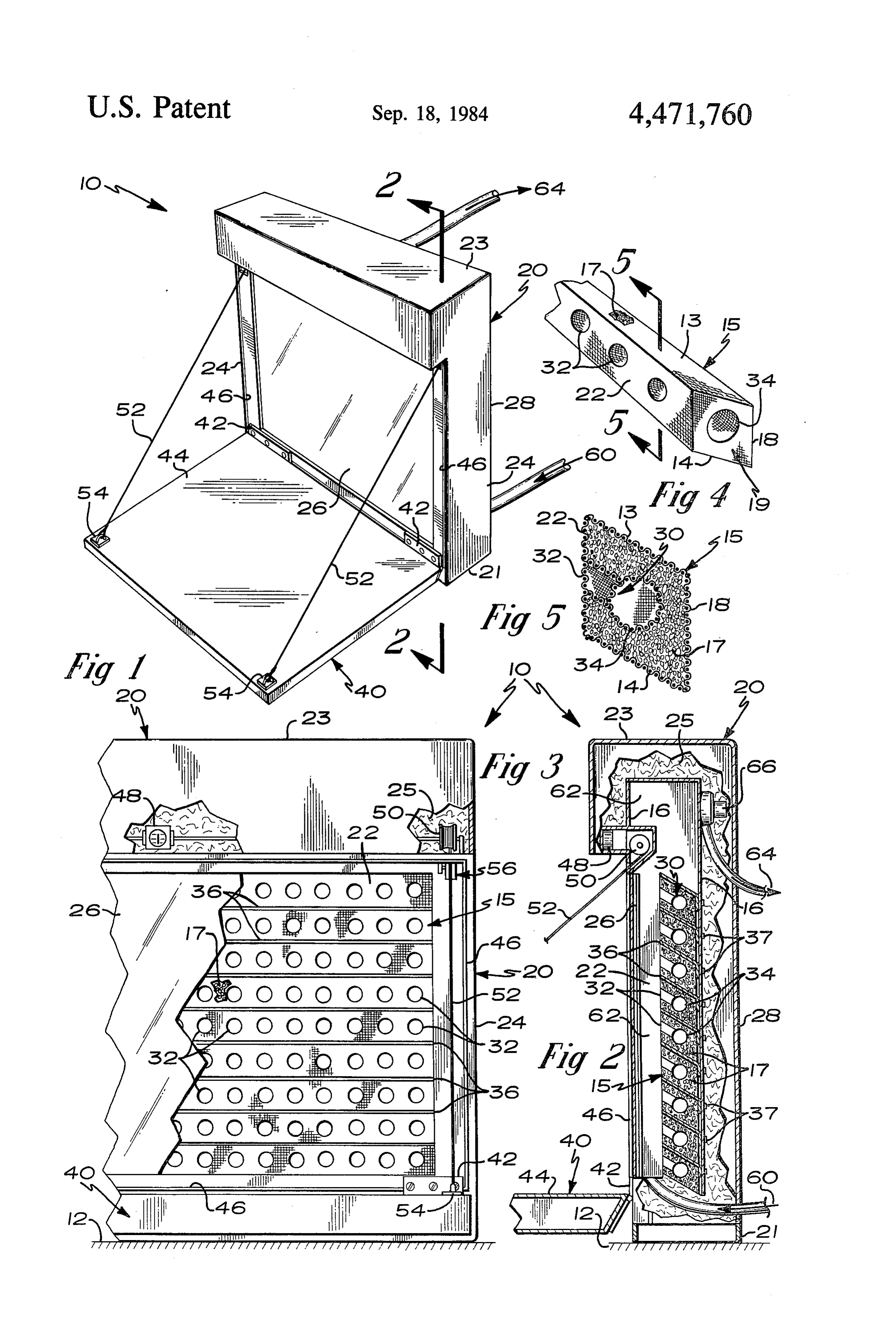
DESCRIPTION OF THE DRAWINGS bution of solar radiation which traverses through the FIG. 1 is a front perspective view of an embodiment individual inner chamber tunnels 34. The brackets 36 of the combined solar collector and storage device. may be aligned either horizontally or vertically depend FIG. 2 is a side cross sectional view taken along ing on the user's place of construction. The brackets 36 cutting plate 2-2 of FIG. 1. 2O also permit the racks 15 and the tunnels 32 and 34 to be FIG. 3 is a front partially cut-away view of the com stacked and spaced in a modular arrangement as shown bined solar collector and storage device of FIG. 1. in FIG. 4. This provides for expansion or reduction of FIG. 4 is an enlarged front perspective view of the the rock supply 17 within the housing 20. intersecting tunnels of the device. The invention 10 also includes a front insulating door FIG. 5 is a cross-sectional side view of the intersect- 25 40 which is connected to the housing 20 by means of ing tunnels of FIG. 4 taken in the direction of cutting hinges 42. The front insulating door 40 is movable be plane 5-5 of FIG. 4. tween an open position, as shown in FIG. 1, wherein
Description of the preferred
solar radiation is allowed to impinge directly onto the
Embodiment
front face 22 of the housing 20, and a closed position 30 (not shown), wherein the front insulating door 40
Referring now to FIG. 1, a combined solar collector closely confronts the window 26 so that solar energy and storage device 10 is positioned above the ground may be retained within the housing 20 during condi surface 12 and includes a housing 20 having a base 21, a tions when the sun's rays have been diminished. For front face 22, a top wall 23, a plurality of side walls 24, instance, such conditions are present during nighttime a clear front window 26, a frame 16 and a rear wall 28. 35 or prolonged overcast periods.
The base 21 is supported above the ground surface 12 in The inner surface 44 of the door 40 is coated with a rigid permanent fashion in any manner known to the sunlight reflecting material. This permits solar radiation art. The rear wall 28 is preferably formed of plywood, impinging on the door 40 when the door 40 is in its open metal or any other suitable material and is joined to the position to be reflected onto the front face 22 of the base 21. The side walls 24 are also joined to the base 21. 40 housing 20 and thereby increases the potential solar The housing 20 also includes a plurality of wire mesh radiation which impinges upon the front face 22 of the racks 15 which retain and store a quantity of rock 17. housing 20.
Preferably, a reasonable size diameter rock 17 in the one The housing 20 also includes a gasket 46 adjacent the to two inch diameter size range is placed within the front window 26 which permits the front insulating wire mesh rack 15. The arrangement of the rock 17 45 door 40 to sealably close against the front window 26 of within the housing 20 is illustrated in FIGS. 2 and 5. As the housing 20 when the door 40 is in its closed position. shown in FIGS. 4 and 5, the wire mesh racks 15 may This prevents most stored energy from escaping the include a top 13, a bottom 14, a back 18 and a plurality housing 20 and thus increases the potential heat storage of sides 19. However, in an alternative embodiment, the capacity which may be retained by the housing 20 when top 13, back 18 and the sides 19 are not necessary for the 50 the door 40 is in its closed position. device 10 to function properly. The front face 22, the The movement of the door 40 between its open and base 21, the frame 16 and the side walls 24 cooperate to closed positions is facilitated by a door motor 48 which retain the rock 17 within the housing 20. The heat ab is mounted adjacent the frame 16. The door motor 48 sorbing capacity of the rock 17 may be increased by drives a winch 50 connected adjacent thereto. A cable painting the rock 17 with a flat paint highly suitable for 55 52 is attached to the door 40 by cable connectors 54 and energy absorption. extends to and is connected with the winch 50. Upon A plurality of intersecting tunnels 30 is generally actuation of the door motor 48, the cable 52 is wound or illustrated in FIGS. 2, 4 and 5. The intersecting tunnels unwound by the winch 50 so that the door 40 may be 30 include a plurality of sunlight entry tunnels 32 and a automatically raised or lowered between its open and plurality of inner chamber tunnels 34, both preferably 60 closed positions. A door switch 56 enables the door formed of one inch square metal mesh. The wire mesh motor 48 to stop when the door 40 is closely confined racks 15 define the walls of the sunlight entry tunnels 32 against the gasket 46.
and inner chamber tunnels 34. The sunlight entry tun The device 10 also includes a blower means by which nels 32 are arranged at closely spaced intervals. The cold air is transferred through the housing 20 and exits sunlight entry tunnels 32 are intersected by a plurality 65 as hot air for subsequent use. A cold air inlet 60 is lo of inner chamber tunnels 34. The inner chamber tunnels cated adjacent the base 21 of the housing 20 and permits 34 are horizontally aligned at closely spaced intervals cold air to enter the housing 20. The cold air passes and pass through the interior rock 17. The longitudinal from the cold air inlet 60 into a hot air collection cham 5 ber 62. In the hot air collection chamber 62, the cold air door 40 reaches its closed position. The door 40 can be is warmed by the build-up of heat produced by the solar returned to its open position in a similar manner. radiation impinging on the rock 17 contained within the Cold air enters the housing 20 through the cold air wire mesh racks 15. The hot air collection chamber 62 inlet 60. The cold air is accumulated in the hot air col is located between the front window 26 and the front lection chamber 62 where the cold air is exposed to the face 22 of the housing 20. The hot air accumulating in heat which has accumulated within the rock 17 and is the chamber 62 is removed from the chamber 62 by a transferred by conduction to the hot air. The hot air squirrel cage fan 66 generally located adjacent the contained within the hot air collection chamber 62 is frame 16 above the wire mesh racks 15. The hot air is moved out of the housing 20 for discharge through the exited by the fan 66 to a hot air outlet 64 for subsequent 10 hot air outlet 64 by means of a fan 66. The hot air is now discharge and use. ready for use, such as in the duct system of a structure. An insulating layer 25 also allows the hot air collec While the preferred embodiments of the present in tion chamber 62 to reach a higher operating tempera vention have been described, it should be understood ture since potential heat dissipation from the housing 20 that various changes, adaptions and modifications may is further reduced. The insulation material used for the 15 be made therein without departing from the spirit of the insulating layer 25 is preferably fiber glass insulation, invention and the scope of the appended claims. but other thermal insulating materials known to the art What is claimed is:
may be substituted. 1. A combined solar collector and storage device for FIGS. 1 and 2 illustrate the combined solar collector storing and collecting solar radiation for use above and storage device 10 in a generally vertical arrange 20 ground level for heating a building and usable with a ment. The device 10 can also be designed in an angular quantity of rock comprising:
arrangement wherein the front face 22 may be inclined a plurality of intersecting tunnels formed of rigid to the vertical by some specific angle so that the device mesh including a plurality of sunlight entry tunnels 10 can intercept the maximum potential solar radiation spaced from one another and a plurality of inner impinging on the surface at a particular geographic 25 chamber tunnels spaced from one another, said location. sunlight entry tunnels having their longitudinal In operation, the front insulation door 40 is moved to axes generally aligned with the direction of the its open position during periods of sunlight, as shown in sun's rays allowing the solar radiation to impinge FIGS. 1 and 2. The sun's rays pass through the clear directly into said sunlight entry tunnels, said inner front window 26 of the housing 20 and directly impinge 30 chamber tunnels intersecting said sunlight entry on the rock 17 filling the wire mesh racks 15 adjacent tunnels at closely spaced intervals so that the solar the front face 22. Interstitial spacing between the rock radiation may be more effectively absorbed by the 17 allows a portion of the solar radiation to penetrate interior rock;
more deeply to the interior rock 17. This process aids a housing including a plurality of wire mesh racks the interior rock 17 in reaching its potential individual 35 retaining and storing the rock therein and also heating capacity so that overall hot air accumulated in including a front face formed of mesh allowing the the hot air collection chamber 62 is increased. solar radiation to impinge on the rock filling said The solar radiation also directly penetrates deeply housing and thereby penetrating deeply into said along the plurality of sunlight entry tunnels 32. The inner chamber tunnels to accelerate the heating of solar radiation passes through the sunlight entry tunnels the interior rock;
32 until such radiation reaches the intersection of the said housing surrounding said wire mesh racks and sunlight entry tunnels 32 and the inner chamber tunnels said sunlight entry and inner chamber tunnels to 34. The solar radiation traverses through the inner isolate said racks and tunnels from the ambient chamber tunnels 34 heating the interior rock 17. The environment and to retain accumulated heat en arrangement of the plurality of intersecting tunnels 30 45 ergy within said enclosure; including the sunlight entry tunnels 32 and the inner a cold air inlet to permit cold air entry into said hous chamber tunnels 34 increases the heat capacity of the ling;
interior rock 17. In this manner, the interior rock 17 also a hot air collection chamber for accumulating hot air receives a generally even distribution of solar radiation within said housing:
thereby increasing the entire heating capacity of the 50 a hot air outlet for directing hot air for discharge into mesh container 20. the building; and
The front insulating door 40 is moved between its a fan to remove the hot air from said hot air collection open position, as shown in FIGS. 1 and 2, and its closed chamber to said hot air outlet. position (not shown). In the open position, solar radia 2. The combined solar collector and storage device of tion impinging on the door 40 is reflected onto the front 55 claim 1 wherein:
face 22 of the housing 20 as the door 40 is coated with said housing includes a base positionable on the a sunlight reflecting surface. This increases the potential ground level and permanently supported adjacent solar radiation which may be received by the housing the ground level and also having a plurality of side 20. walls permanently supported adjacent the ground In its closed position, the door 40 prevents accumu 60 level and also having a plurality of side walls per lated heat from escaping out of the housing 20. The manently supported adjacent the ground level and door 40 is closed during prolonged overcast conditions a frame, said front face, said base, said frame and or at night by activating the door motor 48 which said side walls cooperating to form said housing causes the winch 50 to rotate thereby winding the cable and retain the rock within said housing. 52 around winch 50 and upwardly lifting the door 40 to 65 3. The combined solar collector and storage device of its closed position. The door 40 is sealed tightly closely claim 1 and further including:
abutting the front window 26 by contacting a gasket 46. a front insulating door which is hingedly connected A door switch 56 shuts off the door motor 48 when the to said base of said housing and is movable between 6 an open position, wherein solar radiation is allowed radiation may be more effectively absorbed by to impinge directly onto said front face of said interior rock;
housing and a closed position, wherein said front a housing including a plurality of wire mesh racks insulating door is extended upwardly contacting retaining and storing the rock therein and also said housing adjacent said front face thereby retain- 5 including a front face formed of mesh allowing the ing solar energy within said housing during condi solar radiation to impinge on the rock filling said tions when the sun's rays have been diminished. housing and thereby penetrating deeply into said 4. The combined solar collector and storage device of inner chamber tunnels to accelerate the heating of claim 3 wherein: interior rock;
said front insulating door includes a sunlight reflect- 10 said housing having a base positionable on the ground ing surface on its inner surface thereby reflecting level and permanently supported adjacent the solar radiation to said front face of said housing ground level and also having a plurality of side when said door is in said open position. walls and a rear wall, said front face, said base, said 5. The combined solar collector and storage device of rear wall and said side walls cooperating to form claim 3 wherein: 5 said housing and retain the rock within said hous said housing includes a front window adjacent said ing;
front face and a gasket positioned about said front a front insulating door which is hingedly connected window permitting said front insulating door to to said base of said housing and is movable between sealably close against said front window when said an open position, wherein solar radiation is allowed to impinge directly onto said front face of said 6. The combined solar collector and storage device of housing, and a closed position wherein said front claim 3 and further including: insulating door is extended upwardly contacting a door motor mounted to said housing and having a said housing adjacent said front face thereby retain winch connected therewith; and ing solar energy within said housing during condi a cable extending from said front insulating door and 25 tions when the sun's rays have been diminished; engaging said winch so that said motor can move said front insulating door including a sunlight reflect said door between said open and closed positions. ing surface on its entire inner surface thereby re 7. The combined solar collector and storage device of flecting solar radiation to said front face of said claim 6 and further including: housing when said door is in said open position; a door switch connected electrically with said door 30 a cold air inlet to permit cold air entry into said hous motor to interrupt current flow to said motor when ing;
said front insulating door is closely abutting against said front window. a hot air collection chamber for accumulating hot air 8. The combined solar collector and storage device of within said housing;
claim 1 and further including: 35 a hot air outlet for directing hot air for discharge into a coating of flat energy absorptive material on the the building;
rocks to enhance energy absorption. a fan to remove the hot air from said hot air collection 9. The combined solar collector and storage device of chamber to said hot air outlet; and claim 2 and further including: a hot air discharge motor driving said fan so that the a plurality of support brackets disposed at generally 40 hot air may be removed from said hot air collection even spaced intervals within said housing, said chamber to said hot air outlet for discharge into the support brackets extending between said front face building.
and said frame and being engaged to said frame, of 12. The combined solar collector and storage device claim 11 wherein:
said support brackets permitting said wire mesh racks, said sunlight entry tunnels and said inner 45 said housing includes a front window adjacent said chamber tunnels to be stacked and spaced in a front face and a gasket positioned about said front modular arrangement so that quantities of rock window permitting said front insulating door to may be removably inserted within said housing. sealably close against said front window when said 10. The combined solar collector and storage device door is in its closed position. of claim 1 and further including: 50 13. The combined solar collector and storage device a hot air discharge motor driving said fan so that the of claim 11 and further including:
hot air may be removed from said hot air collection a door motor mounted to said housing and having a chamber to said hot air outlet for discharge into the winch connected therewith; and building. a cable extending from said front insulated door and 11. A combined solar collector and storage device for 55 engaging said winch so that said motor can move storing and collecting solar radiation for use above said door between said open and closed positions. ground level for heating a building and usable with a 14. The combined solar collector and storage device quantity of rock comprising: of claim 13 and further including: a plurality of intersecting tunnels being formed of a door switch connected electrically with said door rigid mesh including a plurality of sunlight entry 60 motor to interrupt current flow to said motor when tunnels spaced from one another and a plurality of said front insulating door is closely abutting against inner chamber tunnels spaced from one another, said front window.
said sunlight entry tunnels having their longitudi 15. The combined solar collector and storage device nal axis generally aligned with the direction of the of claim 11 and further including:
sun's rays allowing the solar radiation to impinge 65 a coating of flat energy absorptive material on the directly into said sunlight entry tunnels, said inner racks to enhance energy absorption. chamber tunnels intersecting said sunlight entry 16. The combined solar collector and storage device tunnels at closely spaced intervals so that the solar of claim 11 and further including:
Page 7scan →
a plurality of support brackets disposed at generally even spaced intervals within said housing, said support brackets extending between said front face and said frame and being engaged to said frame, said support brackets permitting said wire mesh 5 racks, said sunlight entry tunnels and said inner chamber tunnels to be stacked and spaced in a modular arrangement so that quantities of rock may be removably inserted within said housing.
Provenance
- Collection
- Patents citing this work
- Pages
- 7
- Method
- pdftotext (the PDF's own text layer) + pdftoppm 300dpi page scans
- Patent office record
- patents.google.com →
- Source
- Google Patents citing-documents table
- Assignee
- Wille Franklin P
- Published
- 1984-09-18
- Transcribed from
- patentimages.storage.googleapis.com →