

patent · US4471834A
Modular solar heat storage cabinet
18 September 1984
Text
Page 1bibliographic recordscan →
United States Patent (19.
Schlote
MODULAR SOLAR HEAT STORAGE
CABINET
Inventor: David D. Schlote, Box 158, Dittmer,
Related U.S. Application Data
doned.
(51) Int. Cl. .......................... F28D 17/00; F24J 3/02 52 U.S. C. .......................................... 165/4; 165/10;
3,299,945 1/1967 Rice et al. ............................... 165/4 3,464486 9/1969 Rice et al... ... 126/400X 4,088,266 5/1978 Keyes..... ... 126/400X 4,111,185 9/1978 Swann ..... ... 126/400X 4,114,600 9/1978 Newton ................. . 126/400X 4,145,895 3/1979 Hjertstrand et al... ... 62/438 X 4,170,261 10/1979 Laing et al. ..................... 126/400 X
4,205,656 6/1980 Scarlata ............................... 126/400 4,240,404 12/1980 Franchina. ... 126/400X 4,248,291 2/1981 Jarmul ............................ 126/436 X
OUSE
Alk
4,262,653 4/1981 Holland ............................... 126/400 4,270,523 6/1981 Van Heel. ... 126/435
Primary Examiner-Samuel Scott
Assistant Examiner-Margaret A. Focarino
Attorney, Agent, or Firm-Glenn K. Robbins
A heat storage cabinet for use in solar heating systems and the like. The cabinet is comprised of a pair of open ended shells adapted to be buckled together with shelf like containers of phase change materials to form a tortuous passage for hot air to heat the phase change heat storage material. Intermediate modules may be used between the end cabinets to increase the heat stor age capacity. The cabinets may be made of fiber glass with ledges to resiliently receive the phase change shelves for ready installation. Through appropriate top and bottom openings in the cabinet duct work is pro vided for connection to the building to be heated, hot water tank or the like. The novel construction of the phase change shelves comprises a flat shallow box like construction with internal fins for efficient heat transfer which facilitates installation in the end cabinets and intermediate modules whereby the shelves can be butted up against one another at the connection seams of the cabinet components in the erection of the cabinet in proper registry to form the tortuous passage within the cabinet.
6 Claims, 11 Drawing Figures
O HOUSE
Drawings
Page 2drawing sheetscan →
Page 3drawing sheetscan →
Page 4drawing sheetscan →
Page 5drawing sheetscan →
Page 6drawing sheetscan →
Page 7scan →
number as desired, is inserted between the end cabinet
MODULAR SOLAR HEAT STORAGE CABINET sections the heat storage shelves are all aligned and butted together to define the horizontal passageway
SUMMARY OF THE INVENTION defined by the aligned shelves.
By means of this invention there has been provided a 5 The construction of the cabinet is provided by inner simply assembled heat storage cabinet for use with heat and outer fiberglass shells spaced from one another and ing systems for storing heat from a source of heat for filled with insulation which is desirably polyurethane. use in heating a building, water tank or other desired The rests or supports for the shelves may be in the form space or object to be heated. The heat storage cabinet 10 of angle irons or may be suitably formed from a mold to may be conveniently employed in solar heating systems be an integral flange with the inner cabinet shell. or any other system where there is an excess source of Through the resiliency of the inner fiber glass shell a heat such as furnaces using any type of fuel where it is close friction fit with the shelf supported in the cabinets desired to store heat from a heat surplus source for is provided through close tolerances which facilitates distribution at a later time to the area to be heated. the sliding insertion of the shelves in the cabinet and The heat storage cabinet is particularly designed for 15 their retention therein.
employment with a phase change material of conven The heat storage cabinet has appropriate openings for tional composition where the heat energy distributed is duct work leading to the heat source such as a solar latent heat rather than sensible heat in order to maxi panel system to heat the phase change shelves. Further mize the heat transfer efficiency. Such phase change duct work may be connected to the space to be heated materials are conventional and as an example paraffin wax may be employed as the phase change material in and to a back-up furnace. Suitable valving and instru mentations for opening and closing the duct work may this invention.
The phase change material is stored in the heat stor beThe provided as desired.
age cabinets in shallow rectangular containers or shelvesheat may storage cabinet of this invention without the also be used as a hot water tank by joining shelves which are supported within the cabinet in stag the end cabinet gered vertical rows to provide a tortuous passage for water inlet ductsections together. When so used a cold is connected between the hot water the hot fluid such as hot air from the solar panels or the tank to the heat storage cabinet and a heat exchanger. like used as the heating source for the heat storage An outlet at the top of the heat exchanger is provided cabinet. The shelves may be simply constructed of sheet leading back to the hot water tank at an elevated por metal to form the container which is filled with the 30 phase change material. The sheet metal provides a sim tionThe and circulation is effected by natural convection. above features are objects of this invention. Fur ple means for construction and rapid heat transfer ther objects will appear in the detailed description which combined with internal heat transfer fins make possible an effecient heat exchange system. which follows and will be further apparent to those The heat storage cabinet is essentially constructed of 35 skilled in the art.
two open box-like end cabinet sections which are For the purpose of illustration of this invention pre adapted to be buckled together in sealed relation to ferred embodiments thereof are shown in the accompa provide a closed heat storage cabinet. Intermediate nying drawing. It is to be understood that the drawing cabinet modules may be inserted between the end sec isis for purpose of description only and that the invention not limited thereto.
tions to increase the heat storage capacity as desired.
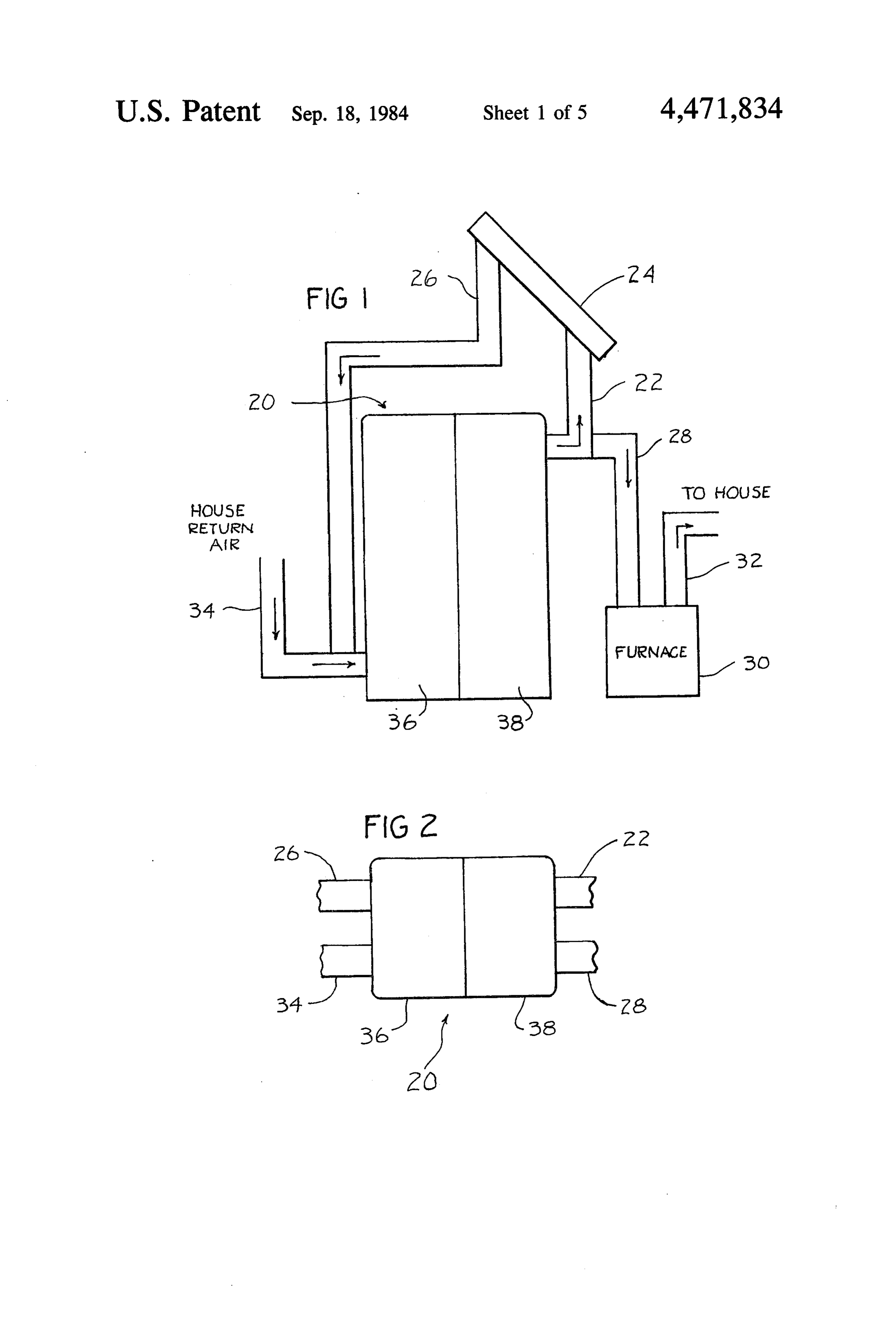
Each of the end cabinets is provided with side walls IN THE DRAWING having flanges on interior wall surfaces to provide a rest or support which receives the shelves containing the FIG. 1, is a view in elevation of the heat storage phase change material in sliding relation in order that cabinet showing installation in a solar heating system the shelves may be readily inserted in the cabinet sec 45 for a house.
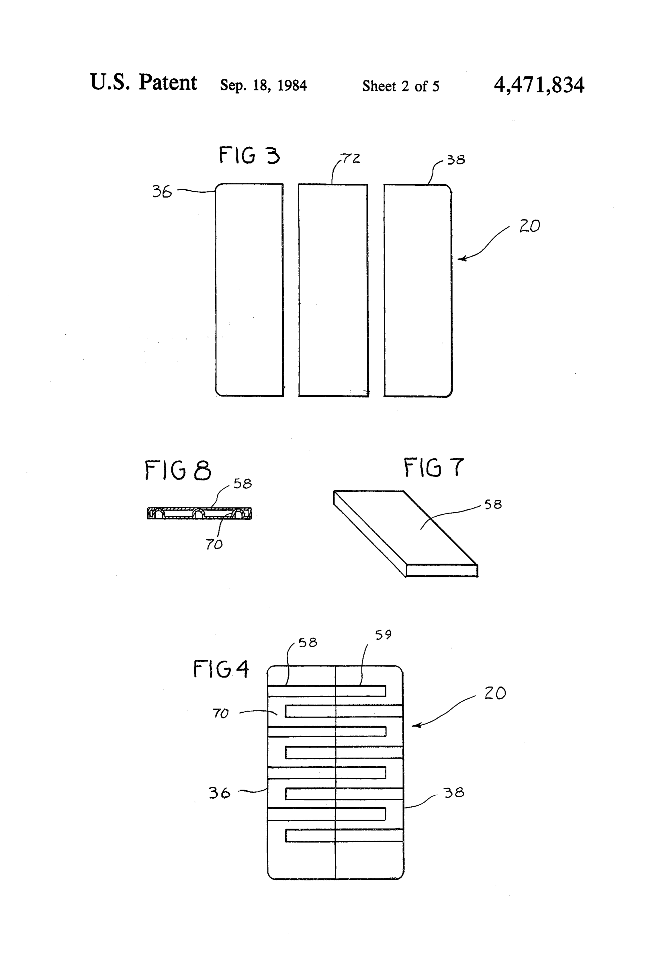
tions. FIG. 2, is a top plan view of the cabinet of FIG. 1. The shelves are supported within the end cabinet FIG. 3, is an exploded view in elevation showing the sections with one end in flush relation to the open por end cabinet sections with an intermediate cabinet mod tion of the end cabinet in order that when the end cabi ule.
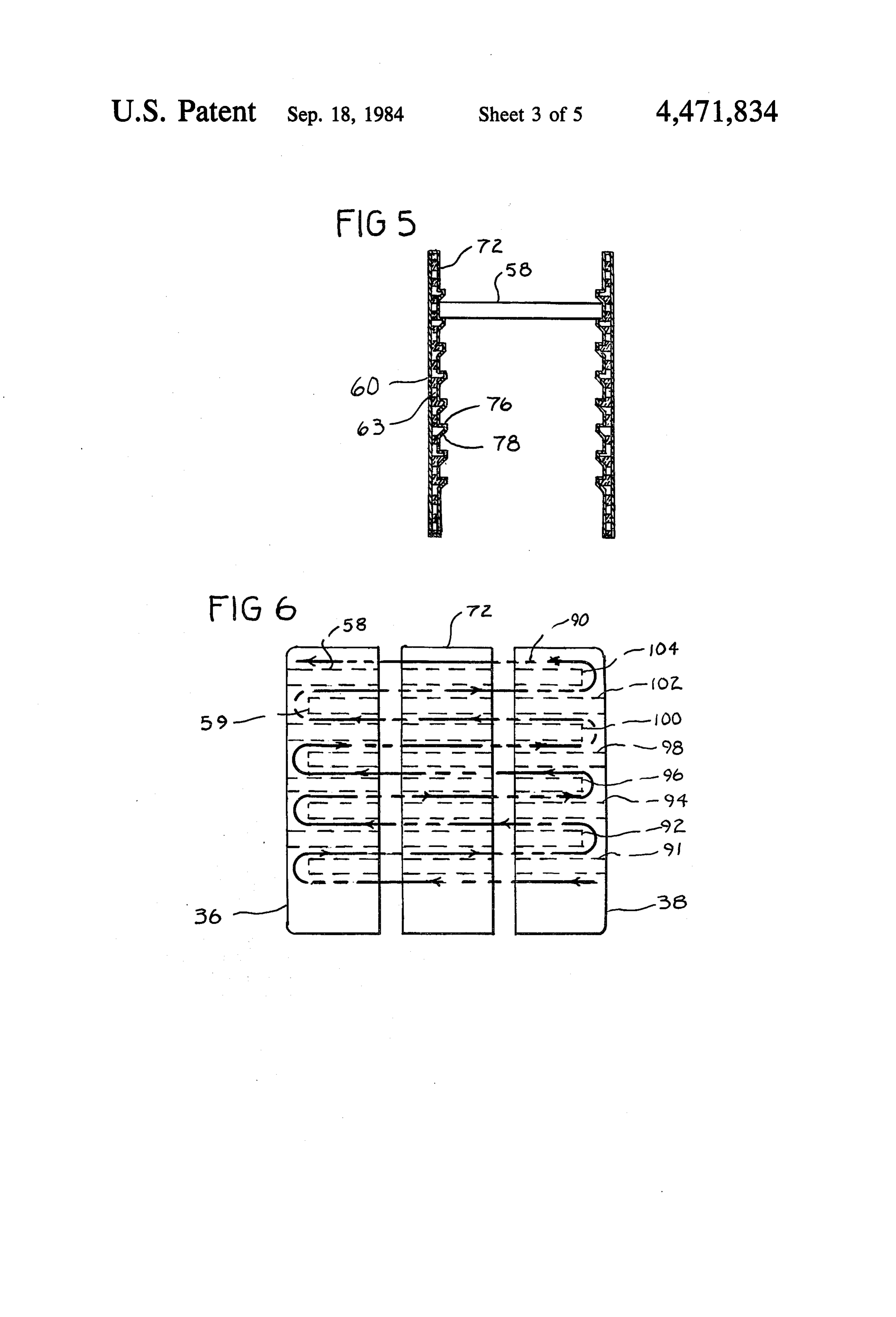
net sections are connected together the shelves in the 50 FIG. 4, is a view in vertical section of the cabinet of end cabinet sections are butted together to define a FIG. 1, showing the staggered shelf arrangement. passageway from one end of the cabinet to the other in FIG. 5, is an enlarged fragmentary view in vertical a tortuous passage back and forth between the shelves. section of the cabinet wall structure and flanges for The shelves are in alternate horizontal rows butted to supporting the shelves.
the end of the cabinet with openings being provided in 55 FIG. 6, is a view taken similarly to FIG. 3, showing the intermediate rows by spacing the shelves from the the staggered shelf arrangement in dotted lines and end of the cabinet. In this manner communication be tortuous flow of hot air from the solar unit. tween the horizontal passage defined by the phase FIG. 7, is a pictorial view of a phase change container change container shelves is provided to establish a tor shelf.
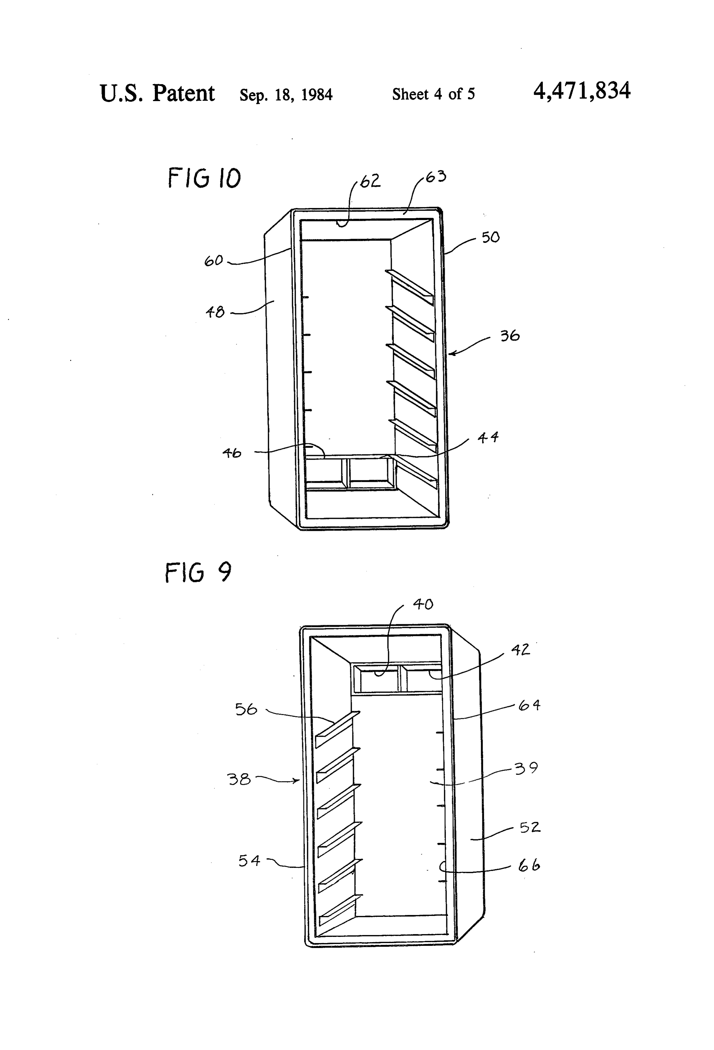
tuous heat exchange path to maximize heat transfer FIG. 8, is a view in vertical section taken through the between the hot fluid from the heat source and the shelf of FIG. 7, showing internal heat exchange fins. phase change material container shelves. FIG. 9, is a pictorial view of a right hand cabinet end The intermediate cabinet module is likewise provided using a modified flange structure for supporting the with supports to receive the phase change material phase change shelves.
shelves. In the intermediate module the shelf is of a 65 FIG. 10, is a view taken similarly to FIG. 9, showing sufficient size to extend completely between the open a left hand cabinet end.
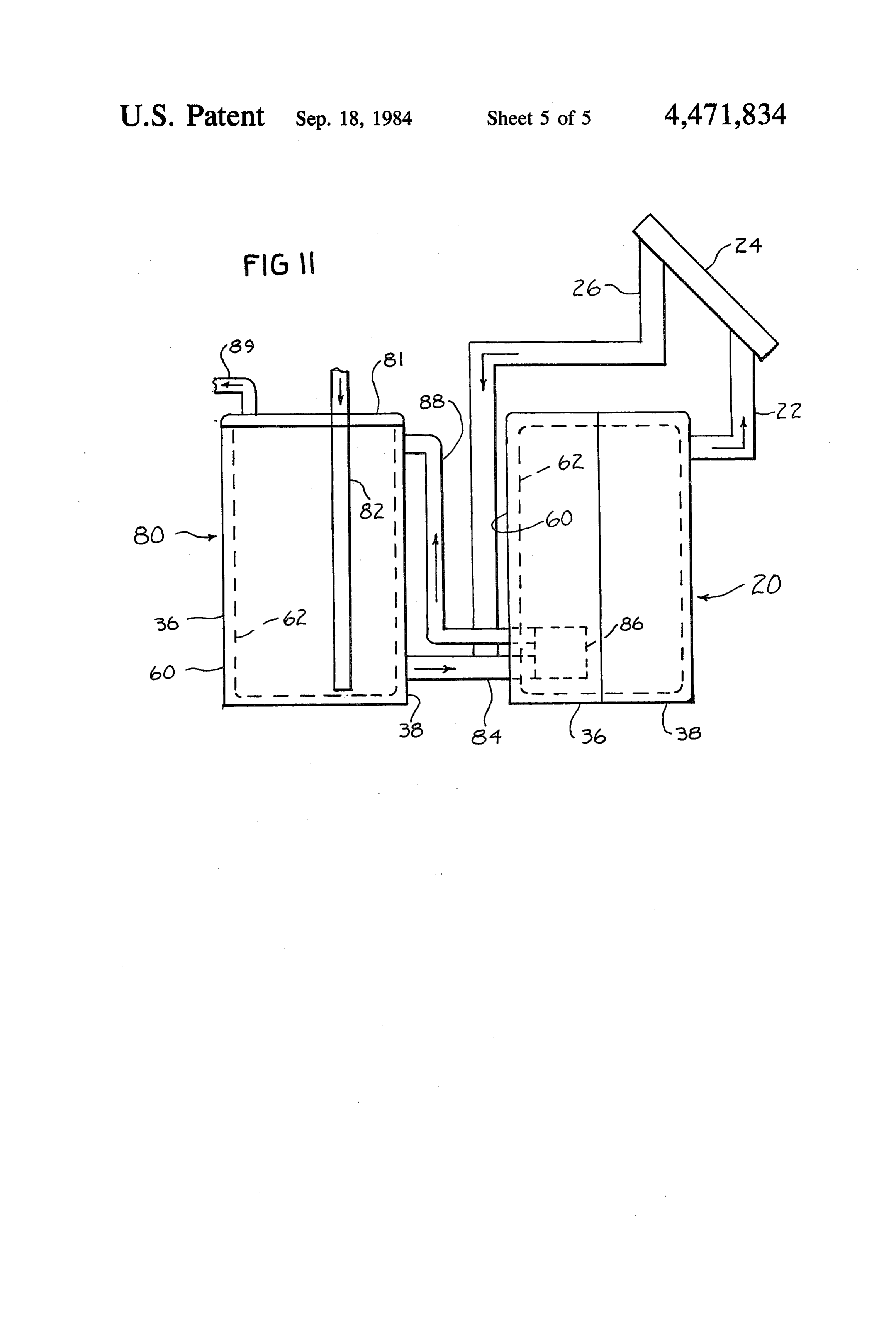
opposite ends and to be in flush relation. By this rela FIG. 11, is a view taken similarly to FIG. 1, showing tionship when the intermediate module, one or more in the cabinet in a solar heating system for a water heating 8 system using the cabinet as a water storage tank with fer which is enhanced by internal fins or ribs 70 to in the inner fiber glass shell shown in dotted lines. crease the heat transfer to the phase change material DESCRIPTION OF THE INVENTION which is contained within the shelves. The phase change material may as an example be paraffin wax for
The heat storage cabinet of this invention is generally latent heat when the phase change material changes indicated by the reference numeral 20 in FIGS. 1, 2, 3, between solid and liquid phase. It will be understood 4 and 11. It is shown in FIGS. 1 and 2 connected by that other phase change materials may be used as well duct 22 leading from the top of the cabinet 20 to an inlet which will be readily understood by those skilled in the in a conventional solar panel 24 having an outlet 26 art.
returning to the bottom of the cabinet 20. This duct O The shelves for purpose of example may be of two work arrangement provides for distribution of the heat sizes represented by shelf 58 shown in FIGS. 4 and 7 generated from the solar panel to the heat storage cabi and shelf 59 shown in FIG. 4, the latter shelf 59 being net. slightly shorter than shelf 58 to provide an air gap be In order to provide for distribution of heat from the tween the stacks of horizontal shelves. In order to un heat storage cabinet to a space to be heated, such as a 15 derstand the size relationship the end sections may be in house or the like, duct 28 leads from the top of the two foot modules with the side, walls being two feet cabinet to furnace 30 and then by duct 32 to the house wide, six feet high and separated from one another by a to be heated. It will be understood that by appropriate three foot distance. The shelves 58 may be about three bypass duct work, valves, and thermostats which are feet long to fit between the side walls in the aforemen conventional and not necessary to be shown as they 20 tioned snug fit when supported upon support ledges 56, form no part of the invention, perse, the furnace can be about two feet wide to extend from the back of the bypassed depending on the heat needs or caused to be cabinet to a flush position with the open end of the operated. A return air duct 34 from the house is con cabinet. The thickness of the shelf may be about four nected to the bottom of the cabinet. inches.
The cabinet 20 as best shown in FIGS. 2, 3, 4, 9 and 25 The shelves 59 are of less width than shelves 58 to 10 is comprised of two shell-like end sections, namely, a left hand section 36 and a right hand section 38, which provide the aforementioned air gap when installed in are adapted to be connected together by conventional the end cabinet sections. For example, they may mea sure about one foot and a half to provide an air gap 70 fastening or affixation means to form a closed cabinet.
The right hand cabinet section is provided with an 30 of about four inches. The other dimensions may be the same as shelf 58.
end wall 39 having openings 40 and 42 which receive The end cabinet sections may be used with one or ducts 22 and 28, respectively. The left hand cabinet more intermediate modules 72 as shown in FIGS. 3 and section is provided with an end wall 43 having openings 44 and 46 which receive ducts 26 and 34, respectively. 6. The intermediate modules are of the same two foot Suitable valves, not shown, may be provided as appro 35 width as the end cabinets and of the same fiber glass priate to close off the ducts as needed. construction as the end sections. The modules are open at both ends in order that they may be interfitted and
Each of the heat storage cabinet end sections has side butted walls opposed side walls, the left hand section 36 side between the end sections. It will be understood walls being designated by the reference numerals 48 and that the side walls of the intermediate module 72 are 50 and the right hand section having side walls desig 40 similarly provided with the same supports 56 as in the nated by the numerals 52 and 54. The side walls in each end cabinets. The supports 56 are employed to support of the end cabinet sections are provided with shelf sup the shelves 58 in each of the horizontal layers in order ports 56 which are in the form of flanges affixed to the that the shelves butt against adjacent shelves in the end side walls. The supports in each of the end cabinets are cabinets to provide the horizontal shelf layers as viewed spaced from one another and in vertical registry with 45 in AFIG. 6.
modified side wall construction is shown in FIG. 5.
one another. The supports are employed to receive shelves 58 which contain the phase change material as This construction comprises outer fiber glass shell 60 will be more fully described hereinbelow. and specially fabricated inner fiberglass shell 72 spaced The construction of the left hand end cabinet section from the outer shell by polyurethane insulation 63. The 36 is provided by outer fiberglass shell 60 spaced from 50 inner shell 72 integral flange like supports 74 formed by inner fiber glass shell 62 by polyurethane insulation 63. an inwardly extending rest wall 76 and a lower wall 78 Similarly the right hand end cabinet section 38 is com slanting backwardly to the shell wall 72. prised of outer fiber glass shell 64 and inner fiber glass The heat storage cabinet 20 is shown in FIG. 11 in an shell 66 separated by polyurethane insulation 68. The installation employing a hot water tank 80. The hot fiber glass shell construction makes possible a simple 55 water tank 80 employs the same cabinet construction as and rugged construction while making possible an effi previously described but without the cut out duct open cient heat transfer barrier to prevent loss of heat. The ings, 40, 42, 44 and 46. The cabinet is molded in cup insulation effectively spaces the fiber glass shells from shaped form and closed by a sealed top 81 of the same one another and further enhances the heat insulating fiber glass construction as that previously described. effectiveness. The fiber glass construction of the inner 60 The cabinet is simply sealed together and employed shell also provides a degree of resiliency in order that without the shelves as an insulated reservoir for hot the shelves may be inserted on the support flanges and Water.
resiliently held thereon in snug and close engagement The tank 80 has a cold water inlet 82 terminating in with the side walls. closely spaced relation to the bottom of the tank. An The phase change material container shelves 58 are 65 outlet 84 leads from the bottom of the tank into the best shown in FIGS. 4 through 8. The shelves are con bottom area of the heat storage cabinet to a heat ex structed of sheet metal to provide a shallow box-like changer 86. Conduit 88 leads from the heat exchanger hollow shelf. The sheet metal provides rapid heat trans to a top portion of the hot water tank.
Page 9scan →
Circulation of the water from the bottom of the tank it is heated and then is returned as hot water through to the heat exchanger in the heat storage cabinet and to conduit 88 to the hot water tank. Hot water is with the top portion of the tank is effected through natural drawn as needed through hot water outlet 89. convection as the water is progressively heated. A hot Various changes and modifications may be made water outlet 89 leads from the top of the tank to a distri within this invention as will be readily apparent to those bution system as desired. skilled in the art. Such changes and modifications are USE within the scope and teaching of this invention as de fined by the claims appended hereto.
The heat storage cabinet of this invention is very What is claimed is:
simply fabricated and installed in the plant or in the field 10 1. A heat storage cabinet for use in solar heating as desired. In the installation of the shelves 58 and 59 in systems and the like which comprises first and second the two end cabinets 36 and 38, the shelves 58 and 59 are box shaped cabinet elements open at one end and simply inserted on the supports in alternate, as best adapted to be closed together in sealed relation at their shown in FIGS. 4 and 6. By this alternate installation open side to form a hollow cabinet, each of said cabinet the automatic butting together relation is effected when 15 elements having opposed side walls having support the two cabinets are connected together at their open means for supporting heat members in spaced vertical ends as shown in FIG. 4. rows extending between said side walls, said heat stor When the cabinets are connected together a tortuous age members further extending from said open end passage 90 defined by the dotted line in FIG. 6 between toward a rear wall of each of said cabinets, the rows of the shelf layers 91, 92, 94, 96, 98, 100, 102, and 104 is 20 said heat storage members alternating between extend established with communication of heat exchange fluid ing into contact with said rear wall and being spaced between the shelves being provided by the air gap 70. therefrom and staggered in said relationship between Once the cabinet 20 has been erected the installation said first and second cabinet elements to form when said in the solar heating system of FIG. 1 is simply effected cabinet elements are closed together a tortuous vertical by the connection of the duct work shown therein. 25 path past said heat storage members between alternate When the duct work has been established the heating rows back and forth toward the rear walls of said cabi fluid such as air, water or the like, passes as an example, net elements, said cabinet being provided with at least in the form of heated air from solar panel 24 through one intermediate cabinet module between said first and duct 26 to the bottom of the heat storage cabinet. The second cabinet elements, said intermediate module hav hot air rises in the tortuous passage 90 past the phase 30 ing opposed side walls having support means for sup change material container shelves 58 and 59 to impart porting heat storage members in spaced vertical rows heat thereto. In this process the heated air gives up heat. extending between said side walls, said side walls hav Return air to the solar panel is introduced back to the ing opposed ends adapted to be butted and sealed panel through duct 22. against the open-ends of said first and second cabinet In the installation of FIG. 1 return air from the house 35 elements.
is introduced to the heat storage cabinet through duct 2. The heat storage cabinet of claim 1, in which the 34 and passes through the tortuous path 90 to be heated support means comprises flange elements connected to and passed through duct 28 and 32 to the house to be the side walls of said cabinet elements and said heat heated. It will be understood that by appropriate ther storage members are in the form of shallow rectangular mostats, valving and the like the duct work to the solar 40 shelves supported upon said flange elements and extend panel and the house may be cut off, modulated or the in substantially abutting relation between said side walls like depending on the heat demands, outside solar heat and said shelves supported in said intermediate cabinet ing conditions and other heating variables. Likewise the module extend between said opposed open ends and furnace 30 may be bypassed or cut into the system as substantially abut against and are aligned with shelves desired. The installation shown in FIG. 1, thus is shown 45 supported in said first and second cabinet elements. only as an exemplification or typical installation with 3. A heat storage cabinet for use in solar heating out limitation of the use of the heat storage cabinet in systems and the like which comprises first and second other systems. box shaped cabinet elements open at one end and The intermediate module 72 may be used alone or in adapted to be closed together in sealed relation at their multiples where desired. When used the heat capacity 50 open side to form a hollow cabinet, each of said cabinet provided by the additional shelves 58 is substantially elements having opposed side walls having support increased as more phase change material is provided as means for supporting heat storage members in spaced a heat reservoir for use when needed. vertical rows extending between said walls, said heat The installation of the intermediate module 72 is sim storage members further extending from said open end ply effected in substantially the same manner as previ 55 toward a rear wall of each of said cabinets, the rows of ously described. Thus the shelves 58 are inserted such said heat storage members alternating between extend that they are flush with the open ends of the module 72. ing into contact with said rear wall and being spaced The module is then connected to the end cabinets 36 therefrom and staggered in said relationship between and 38 as shown in the exploded view of FIG. 6 to said first and second cabinet elements to form when said provide an extended tortuous passage 90. Additional 60 cabinet elements are closed together a tortuous vertical modules 72 may be inserted as desired. path for the passage of a heat exchange fluid past said The use of the heat storage cabinet of this invention is heat storage members between alternate rows back and shown in FIG. 11 in a hot water system. In this system forth toward the rear wall of said cabinet elements, the the cabinet 80 is employed as an insulated simply fabri support means comprising aligned flange elements con cated hot water tank. In this system cold water is intro 65 nected to the side walls of each of said cabinet elements duced through the tank 80 through cold water inlet 82 and said heat storage members being in the form of rigid and passes by natural convection through conduit 84 to shallow rectangular box-like shelves containing a phase the heat exchanger 86 in the heat storage cabinet where change material supported upon said flange elements 10 and extending between said side walls, said side walls ing an inner fiberglass wall being resiliently deformable comprising a hollow panel of fiberglass having an inner to receive said shelves in frictional engagement. wall being resiliently deformable to receive said shelves 5. The heat storage cabinet of claim 4 in which said in fructional engagement, said rectangular shelves being flange elements are fiberglass and are integrally formed comprised of sheet metal and being provided with inter with said inner wall.
nal heat conducting members contacting said phase systems heat and storage cabinet for use in solar heating the like which comprises a plurality of change material. cabinet elements adapted to be closed together in sealed 4. A heat storage cabinet for use in solar heating relation to form a hollow cabinet having opposed side systems and the like which comprises a plurality of 10 walls, opposed end walls, a top and a bottom wall, said cabinet elements adapted to be closed together in sealed opposed side walls having support means for supporting relation to form a hollow cabinet having opposed side heat storage members in spaced vertical rows extending walls, opposed end walls, a top and a bottom wall, said between said side walls, said heat storage members opposed side walls having support means for supporting 15 further extending between said end walls of each of said heat storage members in spaced vertical rows extending cabinets, the rows of said heat storage members alter between said side walls, said heat storage members nating end between extending into contact with each of said walls and being spaced therefrom and staggered in further extending between said end walls of each of said said relationship cabinets, the rows of said heat storage members alter when said cabinetbetween said end walls for forming elements are closed together a tortu nating between extending into contact with each of said 20 ous vertical path for the passage of a heat exchange end walls and being spaced therefrom and staggered in fluid past said heat storage members between alternate said relationship between said end walls for forming rows back and forth between the end walls of said hol when said cabinet elements are closed together a tortu low cabinet, the support means comprising aligned ous vertical path for the passage of a heat exchange flange elements connected to each of the side walls and fluid past said heat storage members between alternate 25 said heat storage members being in the form of rigid rows back and forth between the end walls of said hol shallow rectangular box-like shelves containing a phase low cabinet, the support means comprising aligned change material supported upon said flange elements and extending between said side walls, said side walls flange elements connected to each of the side walls and comprising a hollow panel of fiberglass having an inner said heat storage members being in the form of rigid 30 wall being resiliently shallow rectangular box-like hollow metallic heat con in frictional engagement, deformable to receive said shelves said rectangular shelves being ductive shelves containing a phase change material comprised of sheet metal and provided with internal supported upon said flange elements and having a width heat conducting members contacting said phase change extending to and closely between said side walls, said material.
side walls comprising a hollow panel of fiberglass hav 35 k k c s: se
Provenance
- Collection
- Patents citing this work
- Pages
- 10
- Method
- pdftotext (the PDF's own text layer) + pdftoppm 300dpi page scans
- Patent office record
- patents.google.com →
- Source
- Google Patents citing-documents table
- Assignee
- Schlote David D
- Published
- 1984-09-18
- Transcribed from
- patentimages.storage.googleapis.com →