

patent · US4508101A
Thermal energy storage system
2 April 1985
Text
Page 1bibliographic recordscan →
United States Patent (19)
Carter et al.
(54) THERMAL ENERGY STORAGESYSTEM
(75) Inventors: Don E. Carter; Henry K. Yuen, both of Creve Coeur, Mo.
73 Assignee: Monsanto Company, St. Louis, Mo.
51 Int. Cl. ................................................. F24J 3/02 52 U.S. C. ...................................... 126/436; 252/70;
2,244,612 6/1941 Growley ........................... 252/70 X 2,846,421 8/1958 Pollack ................................ 260/823
3,913,559 10/1975 Dandiker ........................... 126/400 4,063,546 12/1977 Schmid et al. ...................... 126/271 4,13,158 12/1978 Abhat et al. ...... ... 126/400X 4,182,398 1/1980 Salyer et al. ............................ 165/1 4,192,144 3/1980 Pierce ........ ... 126/400X 4,258,696 3/1981 Gopal .................................. 126/400 4,259,198 3/1981 Kreibich et al... ... 126/400X 4,259,401 3/1981 Chahroudi et al. ... 126/430 X 4,290,416 9/1981 Maloney ........... ... 126/400X 4,304,219 12/1981 Currie.... ... 126/430 X 4,326,975 4/1982 Cadet .............................. 126/400 X
FOREIGN PATENT DOCUMENTS
601553 4/1978 U.S.S.R. .............................. 126/400
OTHER PUBLICATIONS
D. Eissenberg et al., “What's in Store for Phase
C. J. Swet, "Phase Change Storage in Passive Solar Architecture', Proceedings of the American Section of the International Solar Energy Society, vol. 5.1, 282-286,
D. H. Kaelble et al., "Crystalline Polymers as Heat
Storage Materials in Passive Thermal Protection Sys tems", Polymer Eng. and Science 15 (9), 673-678, Sep.,
D. A. Sama et al., "Phase Change Fluids for Solar Ther mal Systems', Proceedings of the 80th National Meeting of the AIChE, Nov., 1980.
Primary Examiner-Larry Jones
Assistant Examiner-Carl D. Price
Attorney, Agent, or Firm-Dennis R. Hoerner, Jr.;
Joseph D. Kennedy; James W. Williams, Jr.
A thermal energy storage system for absorption of heat from a heat source having a temperature above a prede termined temperature and release of heat to a heat sink having a temperature below the predetermined temper ature. The system comprises a heat storage mass com prising a condensed state material which changes be tween the solid and liquid phases at about the predeter mined temperature and a compartment for containing the heat storage mass. The compartment includes means providing an area for transfer of heat between a fluid and the material. The material may be an aliphatic di amine corresponding to the general formula
where n is an integer between 4 and 14 inclusive, bis(-
or p-phenylenediamine. Mixtures of these amines with each other may be used, particularly including certain eutectic mixtures having melting points near room ten perature. Also useful are mixtures containing at least one of said amines and water or another agent for low ering the melting point of the amine.
41 Claims, 11 Drawing Figures
Drawings
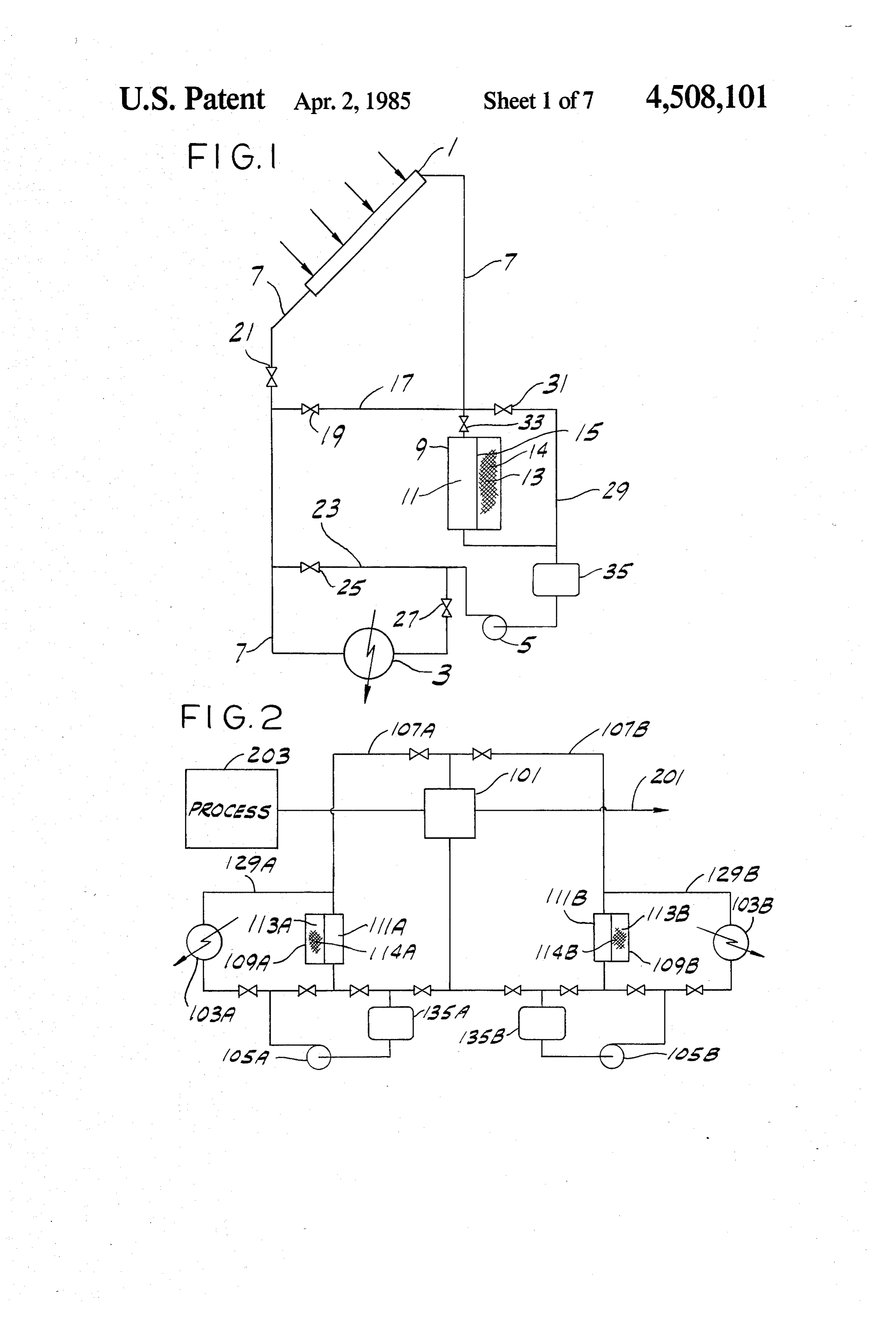
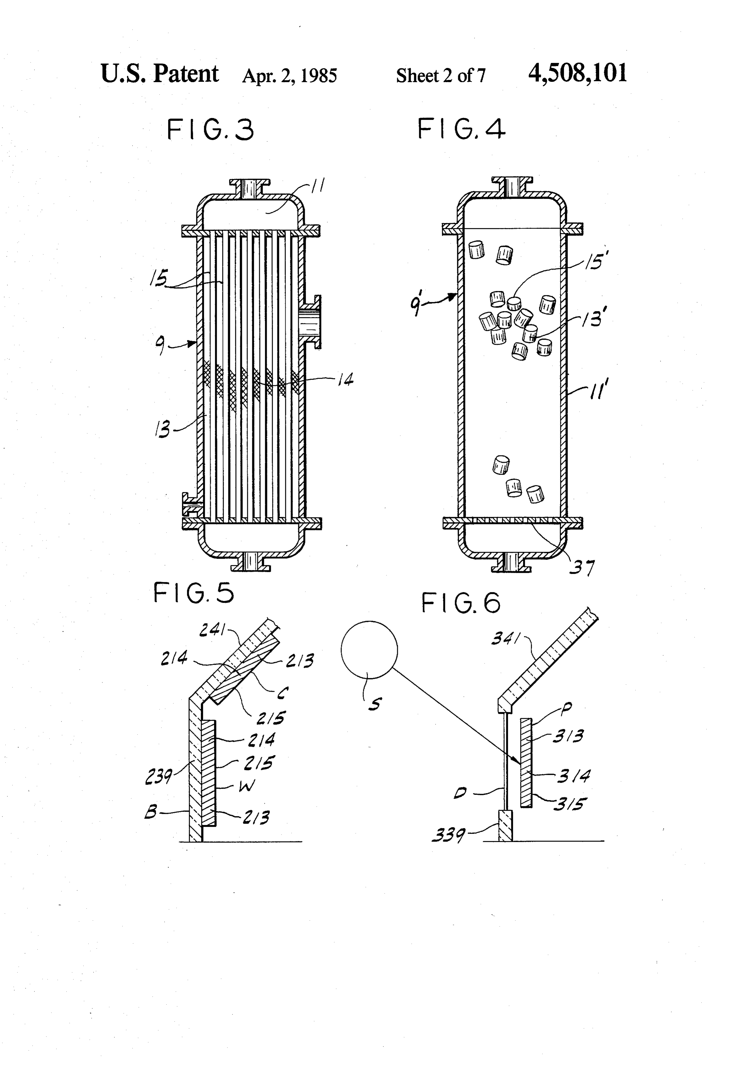
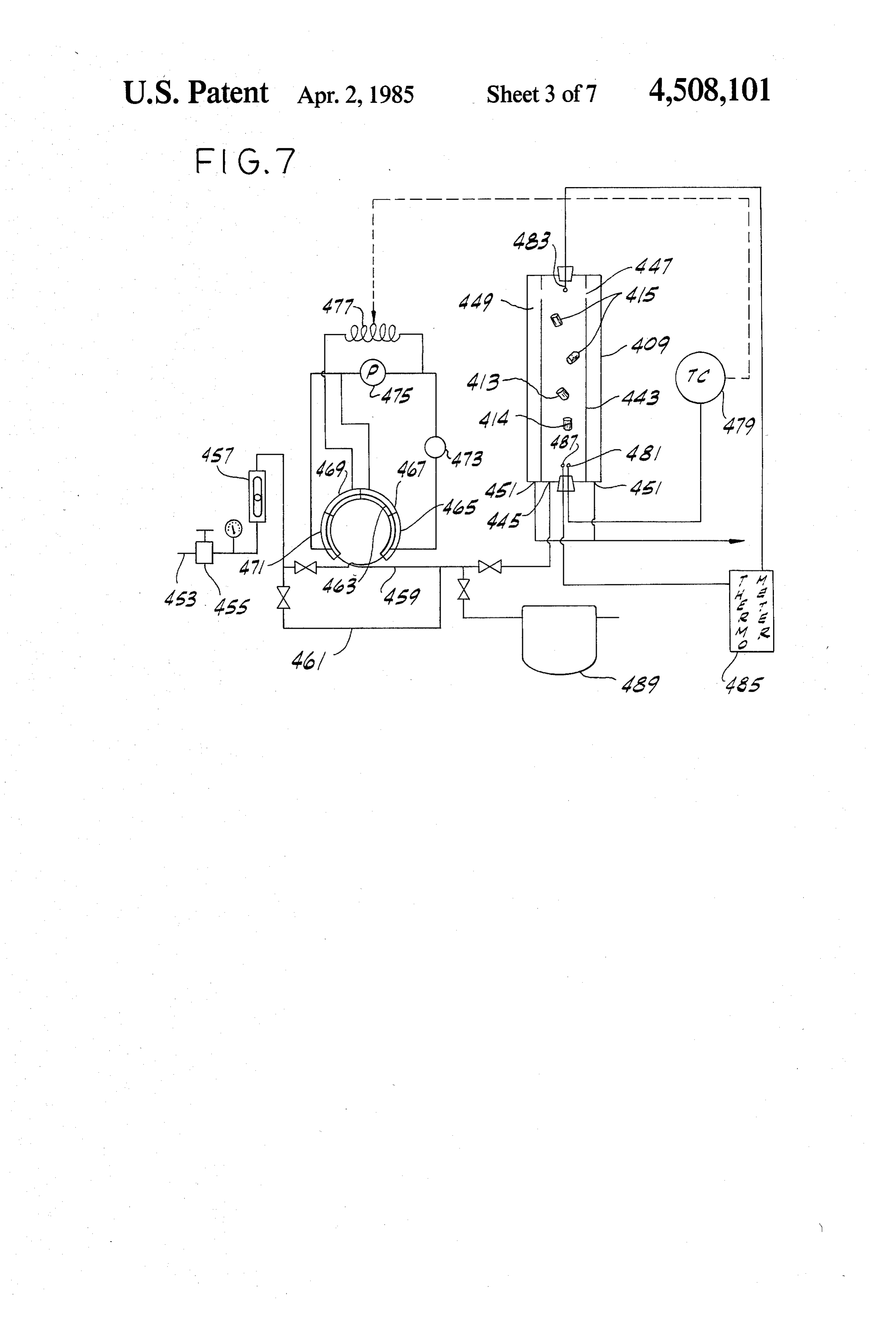
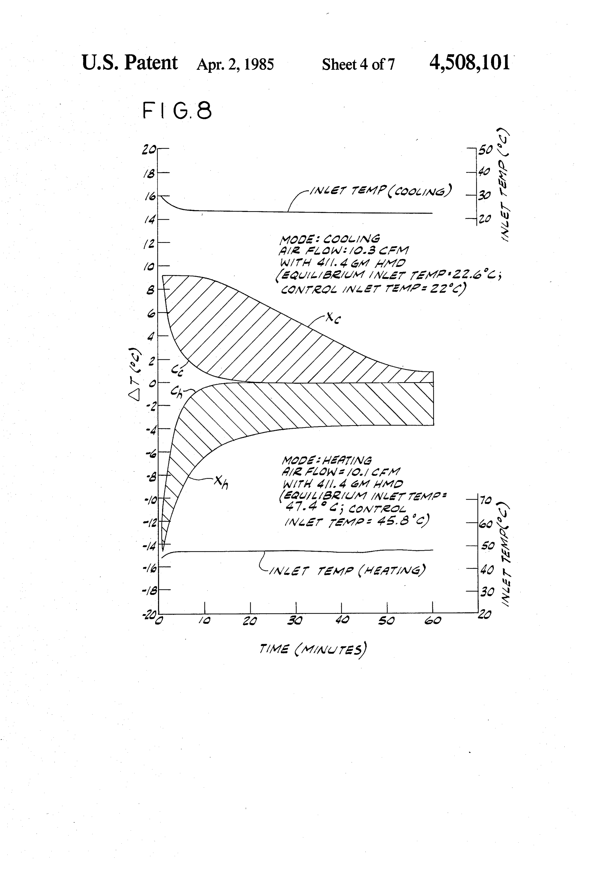
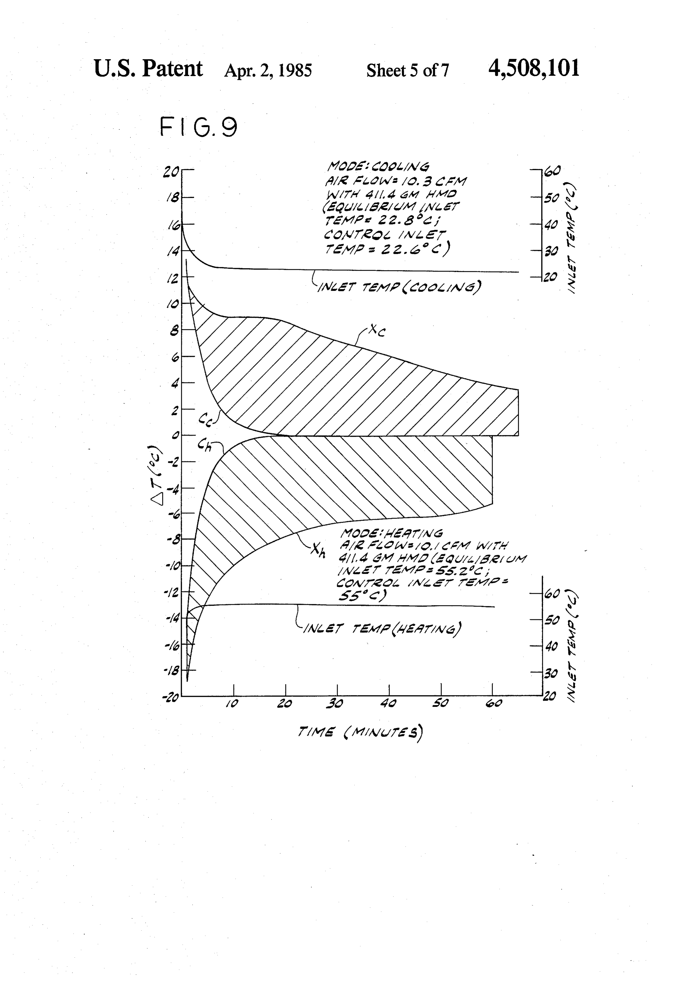
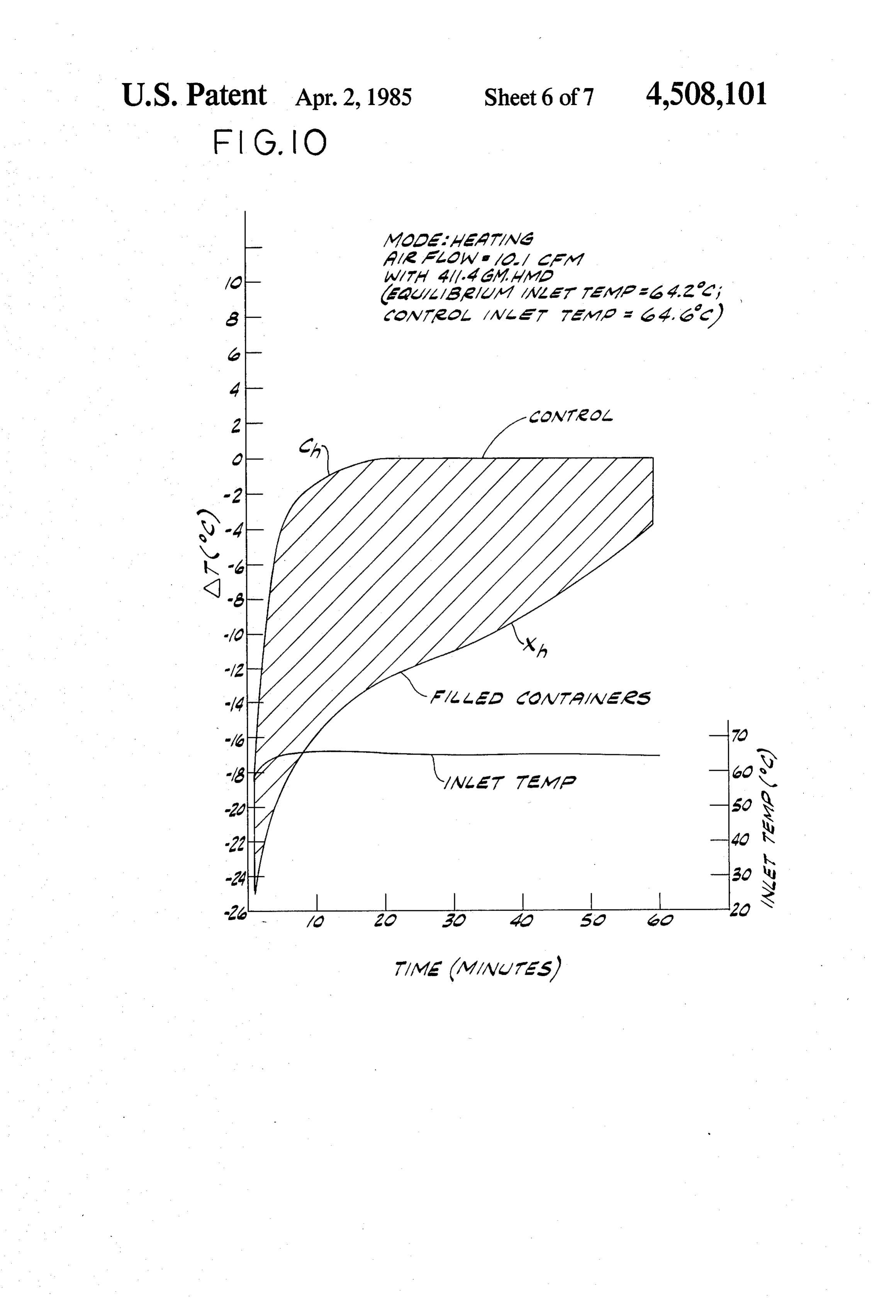
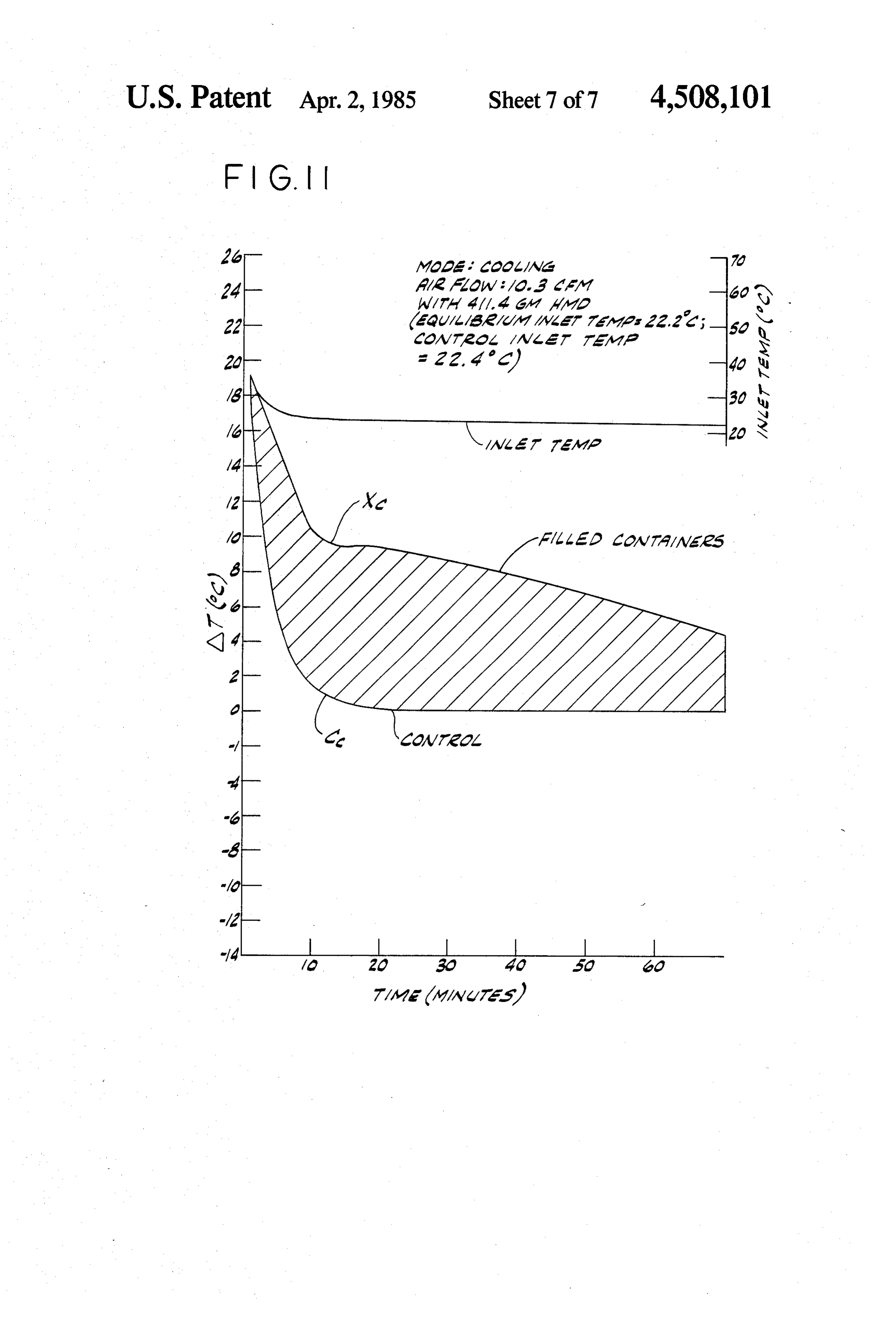
FIG. 1 is a schematic flow diagram illustrating a 30 mal energy storage system include bis(hexamethylene)- system of the invention used for storage of thermal triamine, having a melting point of 36.9° C. (96.3% energy in a solar energy heating system;
FIG. 2 is a schematic flow diagram illustrating a purity) and a heat of fusion of 67.2 cal/g.; 1,8- system of the invention for recovery of low temperature heat of fusion having diaminooctane, a melting point of 52.6 C. and a having a melting point of 67.2 C. and a heat of fusion of
Page 2drawing sheetscan →
Page 3drawing sheetscan →
Page 4drawing sheetscan →
Page 5drawing sheetscan →
Page 6drawing sheetscan →
Page 7drawing sheetscan →
Page 8drawing sheetscan →
Page 9scan →
tial amounts of heat can be stored in a heat storage
THERMAL ENERGY STORAGE SYSTEM material of modest weight and compact dimensions; the provision of such a system and method which allow
BACKGROUND OF THE INVENTION absorption and storage of thermal energy at modest This invention relates to the field of thermal energy temperatures; the provision of such a system and storage systems and more particularly to a novel system method which afford efficient rates of heat transfer to for absorption and release of heat utilizing a condensed and from the heat storage material; the provision of state phase change material. such a system and method which utilize inexpensive and Among the practical problems involved in solar en 10 relatively non-toxic heat storage material; the provision ergy systems is the need for an effective means by of such a system which has a high buffering capacity for which the heat collected during periods of bright sun use in passive heat absorption and release applications; shine can be stored, preserved and later released for and the provision of such a system and method which utilization during the night or other periods when the can be effectively utilized in a solar energy system or in sun is not shining. Traditionally, energy collected dur 15 the recovery of low temperature process waste heat. ing periods of sunshine has been stored in the form of Briefly, therefore, the present invention is directed to sensible heat, typically by raising the temperature of a thermal energy storage system for absorption of heat rocks, water, oil, salt solutions, etc. Subsequent passage from a heat source having a temperature above a prede of a heat transfer fluid over the hot energy storage termined temperature and release of heat to a heat sink system releases the heat which then can be used to heat having a temperature below that predetermined tem water, to provide residential heating, or for other uses. perature. The system comprises a heat storage mass In passive systems, an energy storage system serves as comprising a condensed state material which changes a buffer, absorbing energy from its environment when between the solid and liquid phases at about the prede the surroundings are in the high temperature portion of termined temperature and a compartment for contain a regular temperature cycle (as in daytime) and releas ing the heat storage mass. The compartment includes ing energy to the surroundings during the low tempera 25 means providing an area for transfer of heat between a ture portion of the cycle (as at night). fluid and the material. The phase change material may Storage of the thermal energy in the form of sensible be an aliphatic diamine having the general formula heat creates practical problems in the design and opera tion of a solar heating or passive buffer system. Thus, to provide for storage of adequate quantities of heat en 30 ergy in a solar system, it is necessary to either raise the where n is an integer between 4 and 14 inclusive, bis(- thermal energy storage material to a high temperature hexamethylene)triamine, 3-aminobutylcyclohexylamine or to utilize a large mass of heat storage material. Where or p-phenylenediamine. Mixtures of these amines with high temperatures are used, solar collectors must oper each other may also be used, as may mixtures of at least ate at correspondingly high temperatures, which inhib 35 its their efficiency and increases their complexity. The one of said amines with water or with another agent for lowering the melting point of the amine.
alternative of using a large mass of heat storage material The invention is further directed to a solar heat col necessitates a large space allocation and may also in lection system comprising a solar thermal energy col volve relatively expensive heat transfer apparatus.
In a passive system, the buffering capacity of a sensi lector having means for transfer of solar energy to a heat transfer fluid and heat storage means comprising a ble heat storage material is generally very limited.
Thus, a need has existed for an improved thermal heatfluid exchanger having a passage for flow of heat trans energy storage system which is relatively compact, has fer therethrough and a compartment containing a heat storage mass comprising a condensed state material high buffering capacity for passive use, and can be oper of the type recited above which changes between the ated at moderate temperature for collection and release 45 liquid of heat derived from solar energy or collected from ature toandwhich solid phases at a temperature below a temper the heat transfer fluid may be raised by other heat sources.
Among other heat sources of potential economic collectorthe solar collector. Heat from the fluid heated by the importance are industrial process streams which carry the compartmentis transferred to the material through a wall of waste heat at relatively modest temperature. Such 50 which divides it from the fluid pas streams may not be hot enough for use in steam genera sage. The collection system further comprises means for tion and, depending on the nature of the industrial pro transporting fluid heated by the solar collector to an cess, there may be no practical opportunity to recover outside surface of the compartment wall for transfer of the heat in other conventional ways such as pre-heating heat to the phase change material for melting thereof of feed streams. With the rapid escalation of energy 55 and means for transporting a heat transfer fluid at a costs, a need has existed for improved techniques for the temperature below the freezing point of the phase recovery of low temperature waste process heat. change material to an outside surface of a wall of the compartment for absorption of heat from the material
SUMMARY OF THE INVENTION and freezing thereof. There is heat delivery means for Among the several objects of the present invention, 60 transferring heat to a heat sink from a fluid heated by therefore, may be noted that provision of an improved absorption of heat from the phase change material. system and process for the storage of thermal energy; The invention is also directed to a method for absorb the provision of such a system and process which may ing heat from a source thereof and releasing heat to a be operated to absorb heat from an energy source and heat sink. In accordance with this method, heat is trans release the absorbed heat to a heat sink such as a hot 65 ferred from a heat source to a heat storage mass com water or residential heating system or for utility ser prising a material having a melting point below the vices in an industrial process plant; the provision of temperature of the source, thereby causing the material such a system and method by which relatively substan to absorb energy by melting. Heat is transferred from 10 the molten material to a heat sink having a temperature High thermal conductivity of the phase change material below the freezing point thereof, thus causing the mate contributes to relatively rapid absorption and release of rial to release energy by freezing. In this instance also, heat per unit area of heat transfer surface between the the phase change material comprises an aliphatic di phase change material and its surroundings. From this amine having the general formula singularly favorable combination of moderate melting point, high heat of fusion, and relatively high thermal conductivity, the organic amines used in the method where n is an integer between 4 and 14 inclusive, bis(- that system and of this invention provide unique advantages are not afforded by conventional thermal storage hexamethylene)triamine, 3-aminobutylcyclohexyla 10 materials.
mine, p-phenylenediamine, mixtures thereof with each Hexamethylenediamine, a material whose melting other, mixtures containing at least one of the amines and water, and mixtures containing at least one of said point is at the relatively moderate temperature of 41 C. amines and another agent for lowering the melting point is a preferred phase change material for use in the thereof. method and system of the invention. It has been found The invention is further directed to a composition 15 that hexamethylenediamine has an unusually high heat adapted for use in active or passive thermal energy of fusion of 86.2-2.9 calories per gram (higher even storage systems. The composition comprises a eutectic than H2O), and a thermal conductivity of 0.0021 g. mixture of bis(hexamethylene)triamine and hexamethyl cal./cm. sec.C. in the solid state. As compared to typi ene diamine. cal organic compounds, these thermal conductivities Further included in the invention is a composition are quite high and contribute significantly to effective adapted for use in active or passive thermal energy heat transfer. Generally it has been found that aliphatic storage systems and comprised of a phase change mate amines corresponding to the general formula rial and a nucleating agent therefor. The phase change material may be any of those useful in the systems and 25 method of the invention.
Other objects and features will be in part apparent where n is an integer between 4 and 14 inclusive, serve and in part pointed out hereinafter. effectively as phase change materials in the systems and BRIEF DESCRIPTION OF THE DRAWINGS methods of the inventions. Particular phase change materials which can be used advantageously in a ther
FIG. 1 is a schematic flow diagram illustrating a 30 mal energy storage system include bis(hexamethylene)- system of the invention used for storage of thermal triamine, having a melting point of 36.9° C. (96.3% energy in a solar energy heating system;
FIG. 2 is a schematic flow diagram illustrating a purity) and a heat of fusion of 67.2 cal/g.; 1,8- system of the invention for recovery of low temperature heat of fusion having diaminooctane, a melting point of 52.6 C. and a having a melting point of 67.2 C. and a heat of fusion of
FIG. 3 shows a shell and tube heat exchanger for use 80.6 C.; 1,7-diaminoheptane, in transfer of heat to or from a phase change material in 28.3 C. and a heat of fusion ofhaving 84.5 a melting point of cal/g.; tetramethyl which thermal energy is stored; enediamine, having a melting point of 27.7 C. and a FIG. 4 illustrates an alternative form of heat ex changer in which the phase change material is hermeti having heat of fusion of 87.4 cal/g.; pentamethylenediamine, cally sealed within canisters; a melting point of 15.9 C. and a heat of fusion of FIGS. 5 and 6 illustrate alternative passive thermal melting point3-aminobutylcyclohexylamine having a fusion of 39.7 energy systems of the invention used for temperature cal/g., 1,9-diaminononane having a melting point of buffering;
FIG. 7 is a schematic diagram of a test apparatus used 45 38.0° C. and a heat of fusion of 76.9 cal/g.; 1,10 diamino to demonstrate the effectiveness of hexamethylenedi decane having a melting point of 61.9 C. and a heat of amine as a phase change heat storage material; and fusion of 85.3 cal/g.; 1,14-diaminotetradecane having a FIGS. 8-11 represent temperature profiles obtained melting point of 73.3° C. and a heat of fusion of 72.2 in tests conducted with the apparatus shown in FIG. 7. cal/g.; and p-phenylenediamine having a melting point Corresponding reference characters indicate corre 50 of 140 C. and a heat of fusion of 56.2 cal/g. sponding parts in the several views of the drawings. For any particular application, the phase change ma
Description of the preferred
terial utilized preferably has a melting point roughly centered between that of the heat source and that of the
EMBODIMENTS heat sink. Other important considerations include avail In accordance with the present invention, it has been 55 ability and cost; and it is these factors, as well as its discovered that certain organic amines serve effectively moderate 41 C. melting point, which make hexameth for storage of thermal energy in a range of temperatures ylenediamine a preferred phase change material for which, for each of these compounds, includes its melt solar energy applications. Other materials, such as p ing and freezing points. More particularly, it has been phenylenediamine, whose melting point is relatively found that these amine compounds have exceptionally 60 high, may be uniquely suitable for certain applications high heats of fusion and also exhibit relatively high of the system of the invention for recovery of industrial thermal conductivities. As a consequence of the high process waste heat.
heat of fusion, it is possible to store substantial quantities Although for some services the phase change mate of energy in a relatively low mass and compact volume rial is preferably constituted essentially entirely of a of material by melting the material upon absorption of 65 single compound, mixtures of the aforesaid amines with heat from a heat source having a temperature above the each other are also contemplated. Eutectic mixtures, in melting point and releasing the heat of fusion to a heat particular, may be advantageous in providing a phase sink having a temperature below the freezing point. change material having a melting point lower than that 11 of its constituent materials. A relatively low melting A line 17 and valves 19 and 21 allow collector 1 to be eutectic, for example, one having a melting point of less by-passed while circulating heat transfer fluid between than 10°C., may be used to advantage in a refrigeration heat storage exchanger9 and heat delivery exchanger 3. system wherein relatively cool ambient air is used as a Similarly, a line 23 and valves 25 and 27 allow for by heat sink for withdrawing heat from a heat source. 5 pass of exchanger 3, while a line 29 and valves 31 and 33 Other phase change materials useful in the invention allow exchanger 9 to be by-passed. Thus, the system of include mixtures of at least one of the aforesaid amines FIG. 1 can be alternatively arranged for series circula with water or with another agent for lowering the melt tion of fluid between solar collector 1, exchanger9 and ing point of the amine. Among such agents are cyclic exchanger 3 for simultaneous delivery of heat to the imines such as hexamethyleneimine. Water forms solid O heat sink and storage of heat in the phase change mate hydrates in equilibrium with liquid water. Of particular rial in compartment 13; circulation only between collec interest are mixtures of hexamethylenediamine with tor 1 and exchanger9 for storage of heat by melting the either water or hexamethyleneimine. material in compartment 13; circulation only between Any melting point lowering agent should be compati exchanger 9 and exchanger 3 for release of heat from ble with the amine. Such agents are considered compati 15 compartment 13 by freezing of the phase change mate ble if the mixture forms no more than one liquid phase, rial therein; and circulation only between collector 1 undergoes no chemical reaction other than a reversible and being exchanger 3 in those instances where the heat is removed by the heat sink at a rate which is closely reaction associated with the phase change, and does not in balance undergo gross phase segregation such as to interefere 20 collector 1.with the rate at which energy is received by with the reversibility of the phase change. Air and water are preferred as the heat transfer fluids Other materials such as fire retardants may also be contained in the heat storage mass, provided that there for transport of energy between collector 1, storage exchanger 9 and heat sink exchanger 3 in a system such as no intolerably adverse effects on the melting point as that of FIG. 1. In typical solar systems air is most and homogeneity of the mass. 25 preferred. Alternatively, however, other gases or liq It may thus be seen that a phase change thermal stor age system containing one of the above described mate uids used, may be used. Where water or another liquid is as vented surge tank 35 is provided at the suction rials can be used in a variety of applications including of pump both active systems for energy collection and use and tion head5for to control system pressure and provide suc the pump flow of such heat transfer fluid passive systems for temperature modulation. Prominent 30 can be controlled applications for active energy collection include solar delivery modes by during a the heat storage and heat system of values as described energy systems for residential heating and heating of water, as well as systems for recovery of low tempera below. If desired, different heat transfer fluids may be used for the heat storage and heat delivery modes of ture waste process heat. In passive systems, cycles in the the temperature of the surroundings may be modulated by 35 Inthermal energy storage system. operation of the system of FIG. 1 in accordance absorption of heat from the surroundings when the with the method of the invention, pump or blower 5 ambient temperature exceeds the melting point of the circulates heat transfer fluid through line 7, collector 1, phase change material and release of heat to the sur exchanger9 and exchanger 3. In the start-up phase, the roundings when the temperature thereof is lower than collector is necessarily a part of the circuit. Whether the material's freezing point. Thus, for example, internal start-up operation involves series circulation between wall or ceiling panels containing 3-aminobutylcy exchanger 9 and exchanger 3, by-passing one or the clohexylamine (melting point 26 C.) may be used to other exchangers, or splitting of the flow between ex modulate day/night temperature variations by release changers 3 and 9, depends on the circumstances of the of heat upon freezing during the night and absorption of particular operation. However, in a typical system, heat upon melting during the day. 45 exchanger 3 might initally be by-passed by closing Turning to consideration of active systems, FIG. 1 valve 27 and opening valve 25. Circulation of fluid may be seen to illustrate a typical system of the inven heated at collector 1 through exchanger 9 over the tion for collection and utilization of solar energy. outside surface of wall 15 causes the phase change mate Shown at 1 is a solar collector which includes means for rial in compartment 13 to be heated and melted, thereby transfer of heat energy to a heat transfer fluid. The 50 providing stored thermal energy. Thereafter, circula collector is used to gather energy for delivery to a heat tion may be altered to include exchanger 3 by closing sink via a heat delivery means (heat exchanger) 3 which valve 25 and opening valve 27. If the sun is still shining may, for example, be the coil of a hot water heater or a on collector 1, the fluid may typically be circulated residential radiator. A pump or blower 5 provides for through line 7 to both exchangers and the collector in circulation of a heat transfer fluid between collector 1 55 series (with or without partial by-passing of one or the and exchanger 3 so that energy incident upon the col other exchanger). In time of darkness, collector 1 may lector can be transported to the heat sink via the fluid. be by-passed by closing valve 21 and opening valve 19, A circulating line 7 provides a closed circulating system whereby the fluid circulates only between exchanger 3 interconnecting collector 1, pump or blower 5, and and exchanger 9. Heat is released to the fluid passing exchanger 3. over the outside of wall 15 by freezing of the phase Interposed between collector 1 and pump or blower change material in compartment 13 and the fluid so 5 in line 7 is a heat exchanger 9 having a passage 11 heated is transferred by pump or blower 5 to exchanger therethrough for flow of heat transfer fluid and a com 3 where the energy is transferred to the heat sink. partment 13 containing a heat storage mass 14 compris FIG. 2 illustrates an embodiment of the invention in ing a phase change heat storage material of the type 65 which waste process heat is recovered. In this system discussed above. A wall 15 of container 13 divides it there are two exchangers, 109A and 109B, having com from passage 11 and provides an area for transfer of partments 113A and 113B each containing heat storage heat between the phase change material and a fluid mass (114A,B) comprising a phase change material of moving through passage 11 over the outside surface of the above noted type. Each exchanger further includes the compartment wall. a passage 111A,B through which a heat transfer fluid is 12 circulated by a pump or blower 105A.B. In the embodi surroundings during the night (or other low tempera ment as shown, the heat collection means comprises a ture portion of a regular temperature cycle). In the single waste heat exchanger 101 disposed in a line 201 system of FIG. 5, a wall panel W and ceiling panel C, containing waste heat from an industrial processing each comprising a compartment 213 containing a heat facility 203. Each of exchangers 109A,B is alternately in 5 storage mass 214, are adapted to absorb heat from and circulation with exchanger 101 via line 107A,B or in release heat to the interior of a building B having an circulation with a heat exchanger 103A, B via line outside wall 239 and roof 241. In the system of FIG. 6 129A,B. Each of exchangers 103A,B constitutes means direct energy gain from the sun S is provided by posi for delivery of process waste heat to a heat sink, for tioning a panel P comprising a compartment 313 con example, for space heating, preheating of process mate O taining a heat storage mass 314 adjacent a window D. rials, heating of process wash water, etc. The panel gains both radiant heat from the sun and When exchanger 109A is in circulation with ex convective heat from the surrounding air inside the changer 103A for delivery of heat by freezing of the building. Whenever the temperature of the heat storage phase change material in compartment 113A, exchanger mass exceeds that of the inside air, convective heat loss 109B is in circulation with exchanger 101 for storage of 15 waste process heat through melting of the phase change from panel P contributes heat to the building. For passive environmental temperature buffering material in the compartment 113B. When the material in systems of the type illustrated in FIGS. 5 and 6, it is compartment 113A is substantially frozen and that in desirable to use a phase change material whose melting 111B is molten, the valves (not numbered) are switched point is as close as possible to the desired control tem so that exchanger 109A is in circulation with waste heat 20 perature. A deviation of even 4-6" C. from the control exchanger 101 and exchanger 109B is in circulation temperature has a significant adverse effect on the buff with exchanger 103B for delivery of heat.
In a simplified embodiment of the process of FIG. 2, ering system.
capability of a passive thermal energy storage
It has been discovered that an especially advan the circulating loop through exchanger 101 may be eliminated and the process fluid containing waste heat 25 tageous phase change material is comprised of a eutectic mixture of hexamethylenediamine and bis(hexame from process 203 is passed alternately through exchang thylene)triamine, containing between 50 and 60% by ers 109A,B. weight bis(hexamethylene)triamine. This mixture exhib FIG. 3 illustrates a shell and tube heat exchanger which may be used as exchanger 9 (or 109). In this aitsheat a melting point of between about 24 and 25 C. and of fusion of approximately 65-70 cal/g.
exchanger the shell side comprises the compartment 1330 (113) within which the phase change material 14 (114) is energyBecause the organic amines useful in the thermal contained and the tube side 11 is the passage through storage systems of this invention are subject to subcooling, it is preferable for the heat storage mass to which the heat transfer fluid is passed. In operation of contain the method of the invention, heat flows through walls a nucleating agent for the phase change mate 15 of the tubes. In the present context (somewhat anom 35 rial. Although we do not wish to be bound to any par alously perhaps) the inside surfaces of the tube walls ticular theory it is believed that the crystalline form of constitute the outside surfaces of walls 15 of compart the phase change material is a highly ordered system whose stability is enhanced by relatively strong hydro ment 13. In a further alternative embodiment where the phase change material is inside the tubes and the heat gen bonding forces between adjacent molecules. Such transfer fluid is passed through the shell side, the out hydrogen bonding forces are believed to contribute to sides of the tubes constitute the outside surface of the the unusually high heat of fusion of the phase change compartment walls. material but the highly ordered low entropy nature of FIG. 4 illustrates a still further alternative embodi the crystalline phase is also believed to contribute to the ment of exchanger 9’ in which the phase change materi tendency toward subcooling.
als are contained and hermetically sealed within a plu 45 It has been found that the hydrohalides of cysteine rality of discrete closed containers or canisters 13" hav and tris(hydroxymethyl)aminomethane are uniquely ing outside walls 15'. The canisters are in turn contained effective as nucleating agents for the organic amine within a pipe column 11' which provides a passage for phase change materials used in the systems of this inven heat transfer fluid over the outside surfaces of walls 15'. tion.
The canisters are conveniently supported in column 11" 50 The following examples illustrate the invention. on a perforated plate 37.
Although not shown in the drawings, in a still further EXAMPLE 1 embodiment of the invention, the compartment contain ing the phase change material may constitute a tank or The efficacy of hexamethylenediamine as a phase other vessel through which the heat transfer fluid is 55 change heat storage material was demonstrated using passed for contact heat exchange with the phase change the test apparatus illustrated in FIG. 7. material. Such alternative system is rendered practical Shown at 409 in FIG. 7 is a heat exchanger contain by the relatively low vapor pressure exhibited by the ing a plurality of canisters 413 which constitute com above-noted phase change materials in the range of partments containing hexamethylenediamine phase operation of the thermal storage system. In this embodi- 60 change material 414. Exchanger 409 is cylindrical in ment, area for transfer of heat between the fluid and the construction and contains a concentric internal baffle phase change material is provided, for example, by 443 into which a fluid to be heated or cooled is intro fashioning compartment 11 in the form of a wide shal duced through a fluid inlet 445 at the bottom of the low tank or trough. exchanger. Fluid which has flowed over canisters 413 FIGS. 5 and 6 illustrate typical passive systems in 65 passes through openings 447 at the top of baffle 443 and which wall or ceiling heat storage panels (comfort pan els) absorb heat energy from its environment during into an annular chamber 449 defined by the baffle and the outer wall of exchanger 409. From the annular daytime (or other high temperature portion of a regular chamber, temperature cycle) and releases stored energy to the fluid outlettheports fluid passes out of the exchanger through
Page 13scan →
A supply of air for passage through exchanger 409 is to demonstrate the effectiveness of hexamethylenedi provided by way of a supply line 453 and a pressure amine as a heat storage material. In the heating cycle, regulator 455. The rate of air flow is measured by a the airflow was 10.1 cubic feet per minute, and the inlet rotameter 457. From the rotameter the air is delivered air temperature of 55° C. for the control tests and 55.2 to inlet port 445 via either a heated air line 459 or a cold C. for the tests in which the containers held hexameth air by-pass line 461. Heated air line 459 contains a loop ylenediamine. In the cooling cycle, air flow was 10.3 463 wrapped with an electric resistance heating mantle cubic feet per minute, and the inlet air temperature was comprised of four electric heating tapes 465, 467, 469 22.6° C. during the control test and 22.8 C. during the and 471. A constant head load is applied to tapes 465 tests with hexamethylenediamine in the containers. As and 467 through a Variable transformer 473 connected O in Example 1, the containers held 411.4g. of hexameth to a power source 475. Power to tapes 469 and 471 is ylenediamine. Plots showing the inlet temperatures and provided through a variable transformer 477 that is temperature differentials for the control and filled con controlled by a temperature controller 479 in response tainer runs of this example are set forth in FIG.9. Curve to measurement of the inlet air temperature as sensed by labeling is the same as in FIG. 8.
a thermocouple 481. Exit temperature is sensed by a 15 Integration of the crosshatched areas between the thermocouple 483 and displayed at a thermometer 485 control and opertating curves indicates a heat absorp which also displays the inlet temperature sensed by a tion of 34,200 cal. during the heating cycle and a heat second inlet thermocouple 487. release of 32,800 cal. during the cooling cycle. Rotameter 457 is calibrated by diversion of the air EXAMPLE 3
To provide a basis of comparison, a control run was A further demonstration was conducted using the made initially with containers 413 empty. In the heating apparatus and method described in Example 1. In the mode, air was passed through exchanger 409 at a rate of demonstration of this example, the containers again held 10.1 cubic feet per minute at an inlet temperature of a total of 411.4 g of hexmethylenediamine. During the 45.8 C. Both inlet and outlet temperatures were re 25 heating cycle the inlet temperature was 64.6° C. for the corded as a function of time and a plot prepared of the control run and 64.2 C. for the run in which the ex difference between inlet and outlet temperature. This changer contained hexamethylenediamine. For the plot is set forth as curve Chin FIG.8. A control cooling cooling cycle, the inlet temperature was 22.4 C. for the cycle was run with an air flow 10.3 cubic feet per min control run and 22.2 C. for the run with hexamethyl ute and an inlet air temperature of 22 C. The outlet vs. 30 enediamine. All runs were at an air rate of 10.1 ft.3/min. inlet temperature differential was plotted as a function Plots of the inlet air temperature and heating curves of time and is shown in FIG. 8 as curve C. from the heating cycle are set forth in FIG. 10 while the Containers 413 were then filled with a total of 411.4 plots of the inlet air temperature and cooling curves for g. of hexamethylenediamine, placed inside baffle 443 of the cooling cycle are set forth in FIG. 11. heat exchanger 409 and subjected to heating and cool 35 From the crosshatched areas between control and ing cycles using the same air flow rates as in the control operating curves, it was determined that heat absorp tests. In the heating mode the equilibrium inlet tempera tion on the heating cycle was 48,300 cal. and heat re ture was 47.4 C. while in the cooling mode the equilib lease on the cooling cycle was 43,400 cal. rium inlet temperature was 22.6 C. Plots of the differ EXAMPLE 4 ence between the outlet and inlet temperatures as func tion of time are shown in FIG. 8 as curves Xh for the Using a duPont model 990 differential scanning calo heating cycle and Xfor the cooling cycle. The negative rimeter, melting points, crystallizing points and heat of differential over an extended period of time during the fusion were determined for hexamethylenediamine, heating cycle indicates substantial absorption of heat by bis(hexamethylene)triamine, 1,4-diaminobutane, penta the heat storage mass within containers 413 resulting 45 methylenediamine, 1,8 diaminooctane, 1,9 diaminono from the melting of hexamethylenediamine, and the nane, 1,12-diaminododecane, 1,7-diaminoheptane, 1,10 maintenance of a substantial positive temperature differ diaminodecane and 1,4-diaminotetradecane. In deter ential over time during the cooling cycle is indicative of mining melting point, the sample of the amine tested the release of stored energy by crystallization of the was heated at a rate of 10' C./minute while during the molten hexamethylenediamine. 50 crystallizing point determination the sample was cooled The total quantities of heat energy stored and re at a rate of 0.5 C/minute. The samples were hermeti leased in the heating and cooling cycles, respectively, cally sealed in gold pans and prepared inside a dry box are determined by integration over time of the product before the measurement. Set forth in Table I are the of the air flow rate, the specific heat of air, and the data obtained in these analyses.
temperature difference between control and operating 55 EXAMPLE 5 curves. This integration may be carried out by measure ment of the area of the crosshatched region between the In order to reduce the extent of subcooling, a small curves. Thus, in the heating cycle of FIG. 8, the area amount of tris(hydroxymethyl)aminomethane hydro between the curves is 260 min C. so that, at an air flow chloride was mixed with hexamethylenediamine. Using rate of 345 g/min and an air heat capacity of 0.24 cal/g. 60 the differential scanning calorimetry technique referred °C., the total heat stored was 21,500 cal. On the cooling to in Example 4, melting point and crystallizing point cycle the crosshatched area is 278 min C. and the air determinations were made on the samples of the mix rate 352 g/min, indicating a total heat release of 23,500 ture containing the nucleating agent. Onset of crystalli cal. zation was observed at 29.3-0.5 C.
Example 2 example 6
Using the apparatus illustrated in FIG. 7 and de Mixtures were prepared of bis(hexamethylene)tria scribed in Example 1, additional tests were conducted nine and hexamethylenediamine, and differential scan 14 ning calorimetry tests run to determine melting points from the group consisting of aliphatic diamines having thereof. From these tests it was discovered that a eutec the structural formula tic was formed exhibiting a melting point plateau in the range of 24°-25° C. at a concentration of roughly 50-60% by weight bis(hexamethylene)triamine. Results 5 of the calorimetry tests for samples within the observed where n is an integer between 4 and 14 inclusive, bis(- eutectic range are set forth in Table II. hexamethylene)triamine, 3-aminobutylcyclohexyla
Table i
Calorimetric Measurements for Organic Amines (10' C/min) Scan (0.5 C./min.) Heat of
Onset of Melting Onset of Fusion
Material Melting (°C) Peak (C.) Point (C) Crystallization (C) (cal/g) Hexamethylenediamine 40.7 - 0.1 42.4 - 0.6 40.7 - 0.1 19.6 86.2 2.9 Bis(hexamethylene) 36.4 - 0.0 38.3 0.9 36.9 0.4 28.1 - 0.2 67.2 - 1.5 triamine 1,4-Diaminobutane 27.3 - 0.1 29.6 0.5 27.7 - 0.0 8.9 - 1.8 87.4 - 0.2 Pentamethylenediamine 13.1 0.2 7.6 0.4 15.9 0.3 -9.6 0.3 73.4 - 1.0 1,8-Dianninooctane 520 - 0.3 54.1 - 0.2 52.6 - 1.5 40.2 - 1.5 85.8 + 9.2 1, i2-Diaminododecane 65.1 - 0, 68.7 - 1.2 67.2 - 0.4 55.7 - 1.7 80.6 - 6.2 1,7-Diaminoheptane 27.8 0.6 30.4 0.7 28.3 - 0.6 12.0 - 2.0 84.5 19-Diaminononane 37.1 - 0.3 39.4 - 0.2 38.0 - 0.3 76.9 - 4.3 1,10-Diaminodecane 60.4 - 0.1 62.7 0.2 61.9 - 0.6 85.3 - 2.7 1,14-Diaminotetradecane 70.4 - 0.1 74.5 - 0.5 73.3 - 0.1 72.2 - 2.8
TABLE II 25 mine, p-phenylenediamine, mixtures of said amines with b M: each other, mixtures containing at least one of said
Calorimetric Measurements for BHMT/HMDP Mixtures amines and water, and mixtures containing at least one Weight
Proportion Onset of Peak Melting Heat saidthamines f and an agent for lowering2 the meltin8.
BHMT Melting (°C) (C) Pt. (°C) (cal/g) point thereof. - 50.5% 20 26.9 24.9 69.3 30 2. A system as set forth in claim 1 wherein said heat 36%d 20 o 24.1 674 transfer means comprises a wall of said compartment 54.9% 20.3 - 0.5 25.8 - 0.5 24. 69.0 - 1.9 over the outside surface of which said heat transfer fluid 59.7 19.7 26.2 24.7 56.6 may be passed. bis(hexamethylene) triamine 3. A system as set forth in claim 2 further comprising hexamethylenediamine initially solid 35 heat collection means for transferring heat from an initially liquid external source to a first heat transfer fluid for heating said first heat transfer fluid to a temperature above the melting point of said material, means for transporting
On the cooling scan for the sample containing 54.9% by weight bis(hexamethylene)triamine, the onset of 40 said first heat transfer fluid heated by said external source to said surface for transfer of heat to said mate crystallization was observed at 17.6-0.7 C. Further rial and melting thereof;
tests were run using L-cysteine hydrochloride and tris(- means for transporting a second heat transfer fluid hydroxymethyl)aminomethane hydrochloride as nucle which may be the same as different from said first ating agents. When L-cysteine hydrochloride was used, heat transfer fluid, to said outside surface of said the onset of crystallization was observed at 22.0-0.4 45 wall of said compartment for absorption of heat and when tris(hydroxymethyl)aminomethane hydro from said material wherein said second heat trans chloride was used, the onset of crystallization was ob fer fluid is at a temperature below the freezing served at 20.9.0.4 C. point of said material;
In view of the above, it will be seen that the several and heat delivery means for transferring heat to a objects of the invention are achieved and other advanta 50 heat sink from said second fluid heated by absorp geous results attained. tion of heat from said material. As various changes could be made in the above meth 4. A system as set forth in claim 3 wherein said heat ods and systems without departing from the scope of collection means for transferring heat from said external the invention, it is intended that all matter contained in source comprises a solar energy collector. the above description or shown in the accompanying 55 5. A system as set forth in claim 3 or 4 wherein said drawings shall be interpreted as illustrative and not in a first heat transfer fluid to which heat is transferred from limiting sense. said external source comprises a gas. What is claimed is: 6. A system as set forth in claim 5 wherein said gas 1. A thermal energy storage system for absorption of comprises air.
heat from a heat source having a temperature above a 60 7. A system as set forth in claim 4 further comprising predetermined temperature and release of heat to a heat sink having a temperature below said predetermined means for circulating said first heat transfer fluid be tween said collection means and said outside surface of temperature, said system comprising a heat storage mass said wall of said compartment.
comprising a condensed state material which changes 8. A system as set forth in claim 7 further comprising between the solid and liquid phases at about said prede 65 means for circulating said second heat transfer fluid termined temperature and a compartment for contain between said heat delivery means and said outside sur ing said mass, said compartment including means pro face of said wall of said compartment.
viding an area for transfer of heat between a heat trans 9. A system as set forth in claim 8 comprising a closed fer fluid and said material, said material being selected fluid circulating system containing valve means for 15 alternatively circulating said heat transfer fluid con heat storage means comprising a heat exchanger com tained therein in a first circuit between said heat collec prising a passage for flow of said first heat transfer tion means and said compartment and a second circuit fluid therethrough and a compartment containing a between said compartment and said heat delivery heat storage mass comprising a condensed state 12.S. material which changes between the liquid and 10. A system as set forth in claim 9 wherein said fluid solid phases at a temperature below a temperature circulating system provides for series circulation of said to which said heat transfer fluid may be raised by heat transfer fluid between said collection means, said said solar collector, said compartment having a compartment and said delivery means. wall which divides it from said passage and 11. A system as set forth in claim 3 wherein said heat 10 through which heat may be transferred to said source comprises a hot fluid effluent stream from an material from said first heat transfer fluid heated by industrial processing facility and said collection means said collector, said material being selected from the comprises a heat exchanger for waste heat recovery. group consisting of aliphatic diamines having the 12. A system as set forth in claim 2 wherein said structural formula compartment is contained in a surface heat exchanger. 15 13. A system as set forth in claim 12 wherein said surface heat exchanger comprises a shell and a tubular heat exchanger wherein said compartment is defined by where n is an integer between 4 and 14 inclusive, a spaced between said shell and said tubular heat ex bis(hexamethylene)triamine, 3-aminobutylcy changer, wherein said heat exchange fluid flows 20 clohexylamine, p-phenylenediamine, mixtures of through tubes of said tubular heat exchanger. said amines with each other, mixtures containing at 14. A system as set forth in claim 12 wherein said heat least one of said amines and water and mixtures exchanger contains a plurality of said compartments containing at least one of said amines and an agent comprising a plurality of discrete closed containers for lowering the melting point thereof, dispersed in a vessel that is adapted for passage of said 25 means for transporting said first heat transfer fluid heat transfer fluid therethrough. heated by said solar collector to an outside surface 15. A system as set forth in claim 1 comprising a of said wall for transfer of heat to said material and passive system for modulating the temperature of its melting thereof, surroundings by absorption of heat therefrom when the means for transporting a second heat transfer fluid at temperature of the surrounding exceeds the melting 30 a temperature below the freezing point of said point of said material and release of heat to the sur material to said outside surface of said wall of said roundings when the temperature thereof is lower than compartment for absorption of heat from said ma the freezing point of said material. terial and freezing thereof, and 16. A system as set forth in claim 15 wherein said heat heat delivery means for transferring heat to a heat transfer means comprises a wall of said compartment, 35 sink from said second heat transfer fluid heated by the outside surface of said wall being in contact with a absorption of heat from said material. said heat transfer fluid which comprises the surround 26. A method for absorbing heat from a source ings whose temperature is to be modulated. thereof and releasing heat to a heat sink comprising the 17. A system as set forth in claim 16 wherein the steps of:
melting point of said phase change material is below the 40 transferring heat from a heat source to a heat storage upper temperature portion of a regular temperature mass comprising a material having a melting point cycle of said surroundings and above the lower temper below the temperature of said source thereby caus ature portion of said cycle. ing said material to absorb energy by melting, said 18. A system as set forth in claim 1 wherein said material being selected from the group consisting material comprises hexamethylenediamine. 45 of aliphatic diamines having the structural formula 19. A system as set forth in claim 1 wherein said heat storage mass comprises a mixture of said phase change materials and a nucleating agent therefor.
20. A system as set forth in claim 19 wherein said where n is an integer between 4 and 14 inclusive, nucleating agent is selected from the group consisting of 50 bis(hexamethylene)triamine, 3-aminobutylcy cysteine hydrochloride and tris(hydroxymethyl clohexylamine, p-phenylenedianine, mixtures of )aminomethane hydrochloride. said amines with each other, mixtures containing at 21. A system as set forth in claim 1 wherein said phase least one of said amines and water, and mixtures change material comprises a eutectic mixture of bis(hex containing at least one of said amines and an agent amethylene)triamine and hexamethylenediamine. 55 for lowering the melting point thereof; and 22. A system as set forth in claim 12 wherein said heat transferring heat from said material to a heat sink storage mass comprises a mixture of said phase change having a temperature below the freezing point of material and a nucleating agent therefor. said material thereby causing said material to re 23. A system as set forth in claim 1 wherein said phase lease energy by freezing.
change material comprises a mixture of hexamethylene 60 27. A method as set forth in claim 26 wherein the diamine and water. temperature of the surroundings of said material is mod 24. A system as set forth in claim 1 wherein said phase ulated by absorption of heat therefrom when the tem change material comprises a mixture of hexamethylene perature of the surroundings exceeds said melting point diamine and hexamethyleneimine. and release of heat to the surroundings when the tem 25. A solar heat collection system comprising: 65 perature thereof is lower than the freezing point of said a solar thermal energy collector comprising means material.
for transfer of solar energy to a first heat transfer 28. A method as set forth in claim 27 wherein the fluid, melting point of said phase change material is below the 16 upper temperature portion of a regular temperature cysteine hydrochloride and tris(hydroxymethyl cycle of said surroundings and above the lower temper )aminomethane hydrochloride. ature portion of said cycle. 35. A method as set forth in claim 26 wherein said 29. A method as set forth in claim 26 further compris phase change material comprises a eutectic mixture of ing the steps of: bis(hexamethylene)triamine and hexamethylenedi collecting energy in the form of heat from an external amine.
Source; 36. A method as set forth in claim 35 wherein said transferring heat from said source to a first heat trans heat storage mass comprises said mixture of said phase fer fluid to heat said fluid to a temperature above change material and a nucleating agent therefor. the melting point of said material; 10 37. A method as set forth in claim 36 wherein said transferring heat from said fluid to said material to nucleating agent is selected from the group consisting of melt said material; cysteine hydrochloride and tris(hydroxymethyl transferring heat from said melted material to a sec )aminomethane hydrochloride.
ond heat transfer fluid having a temperature below 38. A method as set forth in claim 26 wherein said the freezing point of said material thereby freezing 15 phase change material comprises a mixture of hexa said material; and methylenediamine and water.
transferring heat to a heat sink from said second heat 39. A method as set forth in claim 26 wherein said transfer fluid heated by transfer of heat from said phase change material comprises a mixture of hexa material.
30. A method as set forth in claim 29 wherein said 20 methylenediamine and hexamethyleneimine. first heat transfer fluid is circulated between a means for 40. A composition adapted for use in active or passive collecting energy from said source and a means for thermal energy storage system comprising a phase transferring heat from said first fluid to said material, change material and a nucleating agent therefor, said said collection means including means for transferring phase change material being selected from the group collected energy to said first heat transfer fluid in the 25 consisting of aliphatic diamines having the general for form of heat. mula 31. A method as set forth in claim 30 wherein said second heat transfer fluid is circulated between said means for transferring heat from said material to said second heat transfer fluid and a heat delivery means for 30 where n is an integer between 4 and 14 inclusive, bis(transferring heat from a fluid to a heat sink.
32. A method as set forth in claim 31 wherein said mine, p-phenylenediamine, mixtures of said amines with heat transfer fluid is circulated in series between said each other, mixtures containing at least one of said collection means, said means for heat exchange between amines and water and mixtures containing at least one said heat transfer fluid and said material, and said deliv 35 of said amines and an agent for lowering the melting ery means. point thereof.
33. A method as set forth in claim 26 wherein said 41. A composition as set forth in claim 40 wherein heat storage mass comprises a mixture of said phase said nucleating agent is selected from the group consist change material and a nucleating agent therefor. ing of cysteine hydrochloride and tris(hydroxymethyl 34. A method as set forth in claim 33 wherein said 40 )aminomethane hydrochloride.
nucleating agent is selected from the group consisting of 3. : k
Provenance
- Collection
- Patents citing this work
- Pages
- 16
- Method
- pdftotext (the PDF's own text layer) + pdftoppm 300dpi page scans
- Patent office record
- patents.google.com →
- Source
- Google Patents citing-documents table
- Assignee
- Monsanto Company
- Published
- 1985-04-02
- Transcribed from
- patentimages.storage.googleapis.com →