

patent · US4512157A
Solar powered fluid heating system
23 April 1985
Text
Page 1bibliographic recordscan →
United States Patent (19)
Weadlock
(54 SOLAR POWERED FLUID HEATING
SYSTEM
(75) Inventor: Glenn E. Wealdock, Dallas, Tex. 73 Assignee: Wetzel Enterprises, Inc., Dallas, Tex.
51 Int. Cl. ................................................ FO3G 7/02 52 U.S. Cl. ..................................... 60/641.8; 60/648;
4,002,031 l/1977 Bell ................................. 126/440 X
4,050,445 9/1977 Huse .................................... 126/422
FOREIGN PATENT DOCUMENTS
Primary Examiner-Stephen F. Husar
Attorney, Agent, or Firm-Michael A. O'Neil
A solar powered fluid heating system includes a thermal collector for vaporizing a refrigerant, a separator for removing any liquid component from the vapor compo nent of the heated refrigerant, and a condenser for transferring heat from the refrigerant vapor to a fluid thereby returning the refrigerant to the liquid phase. Liquid refrigerant is returned from the condenser to the separator, and from the separator to the thermal collec tor. A pump or a compressor is used to force refrigerant through the refrigerant circuit. The pump or the com pressor is actuated by solar energy which is received either from an array of photovoltaic cells or from a generator driven by a turbine which is in turn driven by refrigerant vapor flowing from the separator to the condenser. Secondary refrigerant circuits may be uti lized to preheat the refrigerant in the thermal collector, or to exhaust excess heat therefrom, or both. The ther mal collector and/or the photovoltaic cell array may comprise an assembly having an inverted T-shaped configuration for maximizing output throughout all of the entire day.
37 Claims, 16 Drawing Figures
Drawings
Page 2drawing sheetscan →
Page 3drawing sheetscan →
Page 4drawing sheetscan →
Page 5drawing sheetscan →
Page 6drawing sheetscan →
Page 7drawing sheetscan →
Page 8drawing sheetscan →
Page 9drawing sheetscan →
Page 10scan →
pressurizing apparatus is preferably driven by solar
SOLAR POWERED FLUID HEATING SYSTEM energy, either by means of a plurality of photovoltaic cells or by means of a generator driven by a turbine
TECHNICAL FIELD which is in turn driven by vaporized refrigerant flowing This invention relates generally to solar powered 5 through the vapor conduit from the separator to the fluid heating systems, and more particularly to a solar condenser. Wind energy may also be used to provide powered system for heating water. operating power for the refrigerant pressurizing appara
Background and summary of the
tus, either alone or in combination with a solar powered energy source.
INVENTION O In accordance with more specific aspects of the in The use of sunlight as a heat source is an obvious way vention, the refrigerant pressurizing apparatus may to reduce dependency on energy sources such as gas, comprise a pump which receives liquid refrigerant from oil, coal, etc. The solar heating of water is particularly the condenser and which directs pressurized liquid re attractive because energy available at one time may be 15 frigerant through a portion of the liquid conduit to the stored for use at a later time. Because energy storage is separator. Alternatively, the refrigerant pressurizing so convenient, the use of solar energy to heat water is apparatus may comprise a compressor which receives compatible both with the diurnal cycle of the sun and vaporized refrigerant from the separator and which with the intermittent reduction in the availability of directs pressurized refrigerant vapor through a portion sunlight due to clouds. of the vapor conduit to the condenser. When a com Another advantage inherent in the use of sunlight to pressor is utilized as the refrigerant pressurizing appara heat water involves the fact that the water need not be tus, a check valve is preferably provided at the outlet of heated to high temperatures. Typically, the operating the condenser to prevent refrigerant vapor from enter temperature range for a residential or commercial water ing the liquid conduit. Such a check valve may com heating system is between about 130 and about 150 F. prise a chamber for receiving refrigerant flowing from Such a temperature range results in relatively high effi 25 the condenser into the liquid conduit, a ball positioned ciency, and for this reason solar powered water heating within the chamber and having a density greater than systems do not require the use of highly sophisticated that of refrigerant vapor and less than that of refrigerant thermal collectors. liquid, structure for limiting upward movement of the Realizing the foregoing advantages, numerous at ball in the chamber when the chamber is filled with tempts have been made heretofore to provide a com 30 refrigerant liquid, and a seat for receiving the ball and mercially practical solar powered water heating system. thereby preventing
However, none of the prior art systems has achieved chamber when the the flow of refrigerant out of the chamber is filled with refrigerant real success in the marketplace. Perhaps one reason for this lack of success involves the fact that many of the vapor.
prior solar powered water heating systems have been 35 In accordance with other aspects of the invention, the unduly complicated. Certainly a major factor in the lack thermal collector preferably comprises first and second of consumer acceptance of solar powered water heating flat plates which are spaced apart to define a refrigerant heating chamber therebetween. The first and second systems relates to high initial costs. It has been shown plates that the typical homeowner will not purchase any en preferably extend in divergent planes to define a ergy saving device unless it can be demonstrated that refrigerant receiving zone wherein the plates are spaced the device will pay for itself in energy savings within relatively close to one another and a refrigerant dis about three to four years. charge zone wherein the plates are positioned relatively The present invention comprises a solar powered apart from one another. One or more struts may be fluid heating system which overcomes the foregoing mounted within the refrigerant heating zone to prevent and other disadvantages long since associated with the 45 both inward and outward movement of the plates rela prior art to provide a system that is uncomplicated in tive to each other.
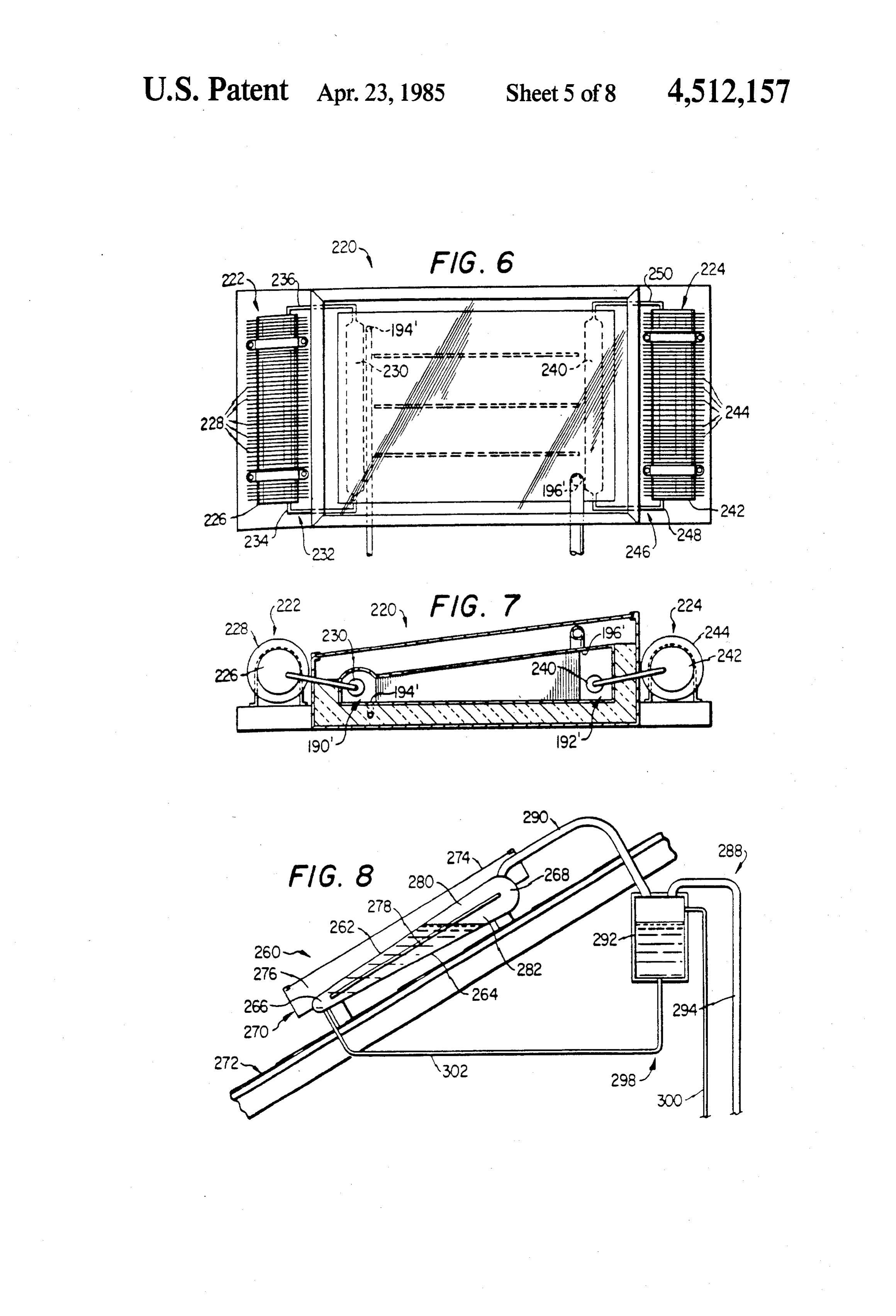
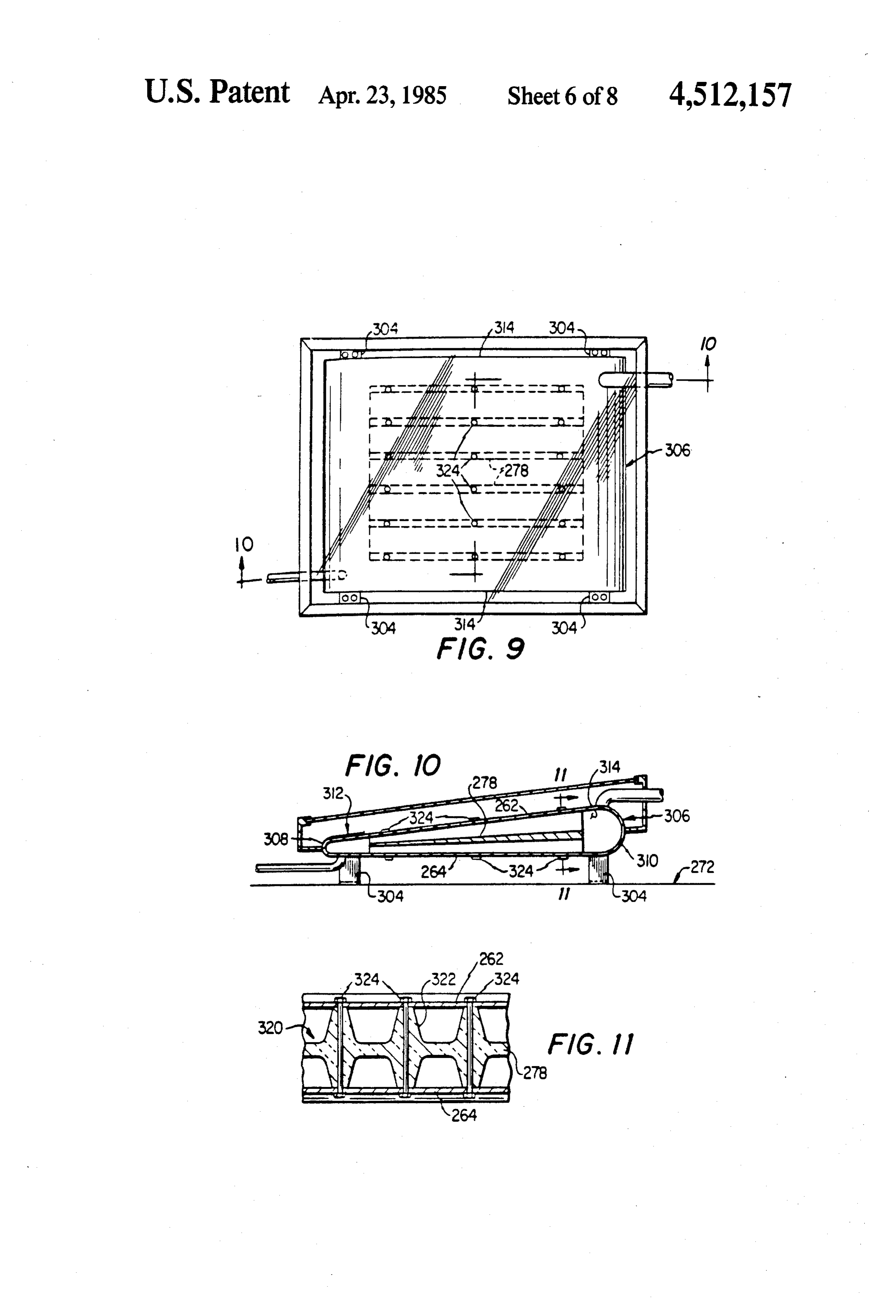
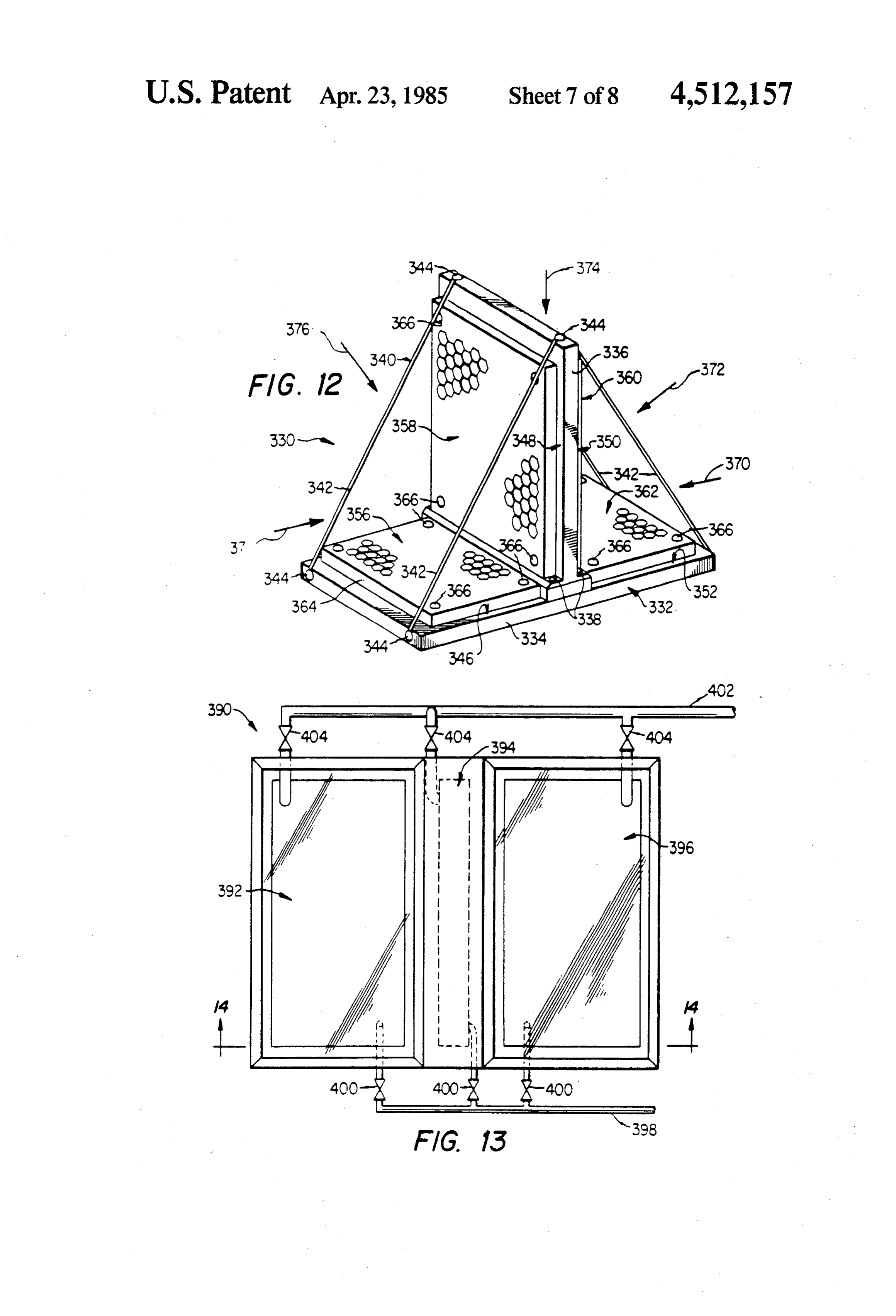
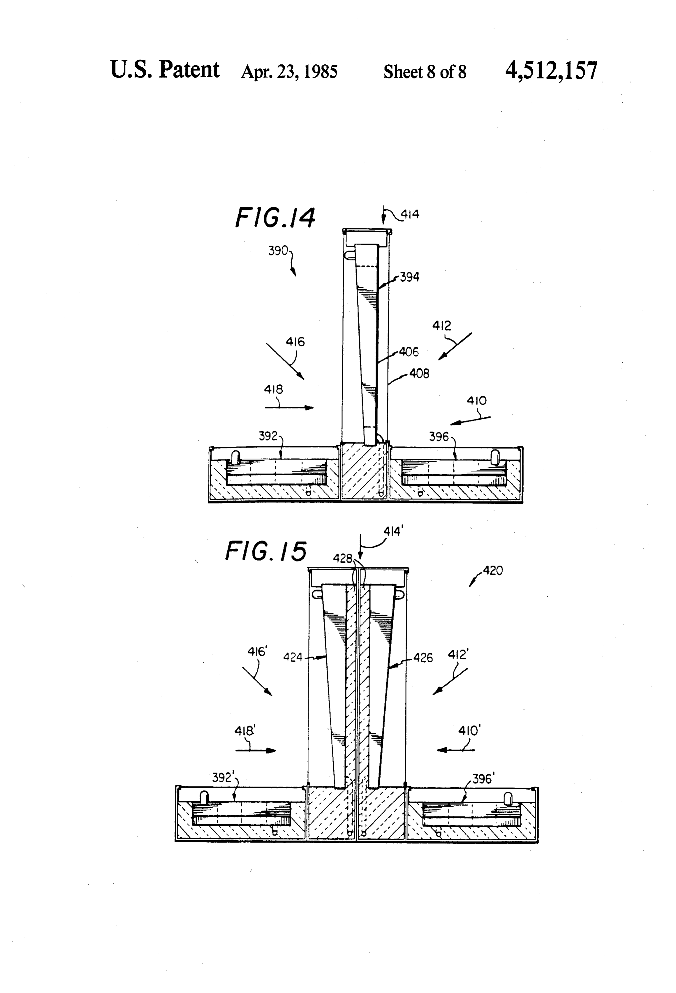
design and therefore low both in initial cost and mainte A third plate formed from a thermally insulative nance costs, and which is readily adapted to effect en material may be mounted within the refrigerant heating ergy savings of sufficient magnitude to return the initial zone between the first and second plates. The third cost in a minimum period of time. In accordance with SO plate separates the refrigerant heating zone to an upper the broader aspects of the invention, a solar powered refrigerant path extending adjacent the first plate and a fluid heating system comprises a quantity of refrigerant, lower refrigerant path extending adjacent the second a thermal collector for heating and thereby at least plate. In such instances the first plate is positioned for partially vaporizing the refrigerant, a separator for sep exposure to sunlight so that refrigerant in the upper arating the vapor component from any liquid compo 55 refrigerant pathis adapted for solar heating. The second nent of the heated refrigerant, and a condenser for re plate is exposed to the ambient atmosphere so that re ceiving the vapor component of the heated refrigerant frigerant in the lower refrigerant path is adapted for and for transferring heat therefrom to a fluid to be heating by heat transfer from the atmosphere. heated. A vapor conduit preferably extends from the In accordance with yet another aspect of the inven thermal collector to the separator and from the separa tion, a secondary refrigerant circuit may be utilized to tor to the condenser, and a liquid conduit preferably preheat the refrigerant within the thermal collector. In extends from the condenser to the separator and from such instances an evaporator is positioned for exposure the separator to the thermal collector. The thermal to the ambient atmosphere and a condenser is positioned collector, separator, condenser, vapor conduit, and within the refrigerant receiving zone of the thermal liquid conduit define a closed refrigerant circuit which 65 collector. The refrigerant in the secondary refrigerant contains the refrigerant, and refrigerant pressurizing circuit has a substantially lower boiling point than the apparatus is employed to cause the refrigerant to flow refrigerant in the primary refrigerant circuit so that through the closed refrigerant circuit. The refrigerant even at low temperatures when the sun is not shining, 11 heat is removed from the atmosphere and transferred to FIG. 12 is a perspective view showing a photovoltaic the refrigerant in the thermal collector. cell assembly which may be utilized in any of the em A similar secondary refrigerant circuit may be uti bodiments of the invention shown in FIGS. 1, 2 or 3; lized to remove excess heat from the thermal collector FIG. 13 is a top view of a thermal collector assembly during periods when the solar powered water heating 5 which may be utilized in any of the embodiments of the system is stagnated. In such instances an evaporator is invention shown in FIGS. 1, 2 or 3; positioned within the refrigerant discharge zone of the FIG. 14 is a sectional view taken along the line thermal collector and a condenser is positioned for 14-14 in FIG. 13 in the direction of the arrows; and contact with the ambient atmosphere. The refrigerant in FIG. 15 is a view similar to FIG. 14 illustrating a the secondary refrigerant circuit has a substantially O modification of the thermal collector assembly shown higher boiling point than the refrigerant utilized in the therein.
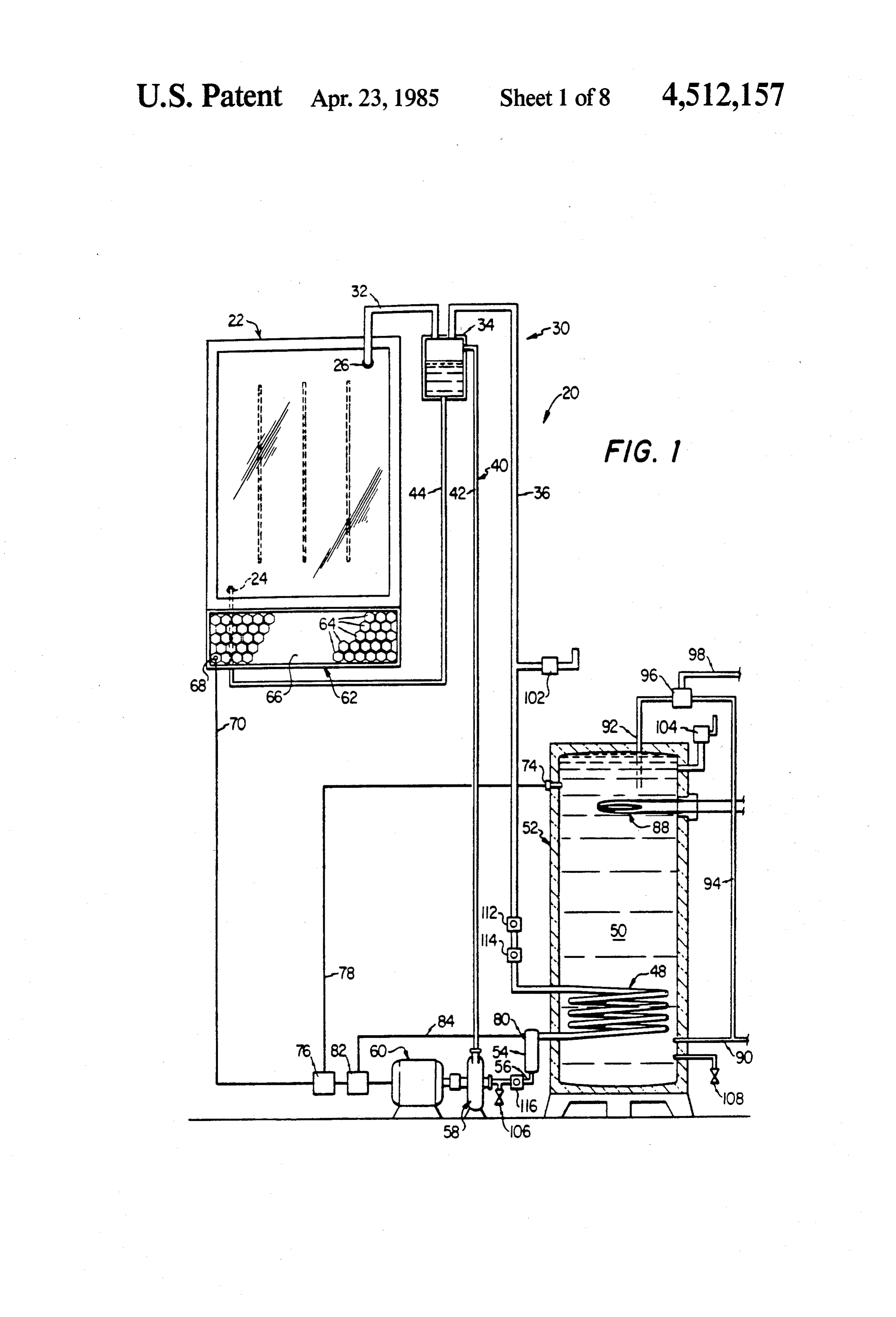
solar powered fluid heating system. Thus, whenever the DETAILED DESCRIPTION temperature of the refrigerant in the thermal collector exceeds the boiling point of the refrigerant in the sec 15 Referring now to the Drawings, and particularly to ondary refrigerant circuit the condenser of the second FIG. 1 thereof, there is shown a solar powered fluid ary refrigerant circuit is effective to transfer excess heat heating system 20 incorporating a first embodiment of from the thermal collector to the ambient atmosphere. the invention. The system 20 is of the type that utilizes Another important aspect of the invention involves arefrigerants refrigerant as the heat transfer medium. For example, of the type known as "FREON” may be the positioning of thermal collector panels, and in those utilized in the practice of the invention. instances in which they are employed, the positioning of 20 The system 20 photovoltaic cell panels, for maximum exposure to solar an inlet 24 and an includes outlet a thermal collector 22 having 26. In use, the thermal collector radiation throughout the entire day. Preferably, the 22 is positioned to receive solar panels are mounted in an inverted T-shaped array. In collector 22 functions responsiveradiation. to The thermal received solar radi this manner the erect panels are positioned for maxi 25 ation to heat the refrigerant flowing therethrough. mum exposure to sunlight at dawn and at dusk, the particular refrigerant utilized in the system 20 isThe se prone panels are positioned for maximum exposure to lected, and the thermal collector 22 is designed such sunlight at midday, and combinations of panels are posi that the refrigerant is received through the inlet 24 of tioned for maximum exposure to sunlight at intermedi the thermal ate hours of the day. The outputs of all the panels are 30 least partiallycollector 22 in the liquid phase and is at added to provide a combined output which is optimized mal collector 22 throughbefore vaporized the flowing out of the ther outlet 26.
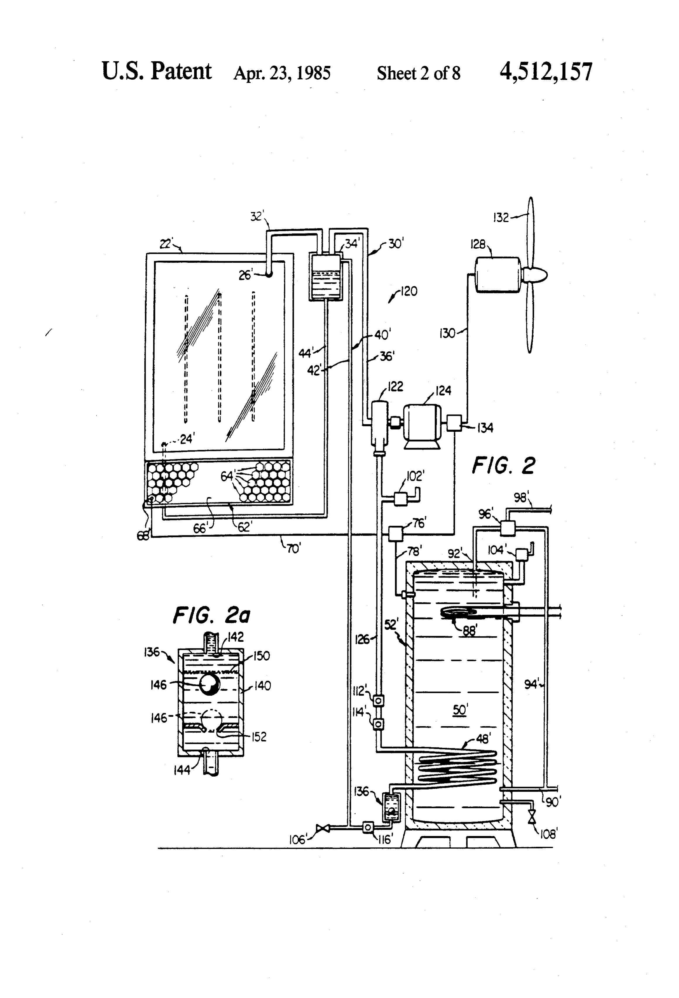
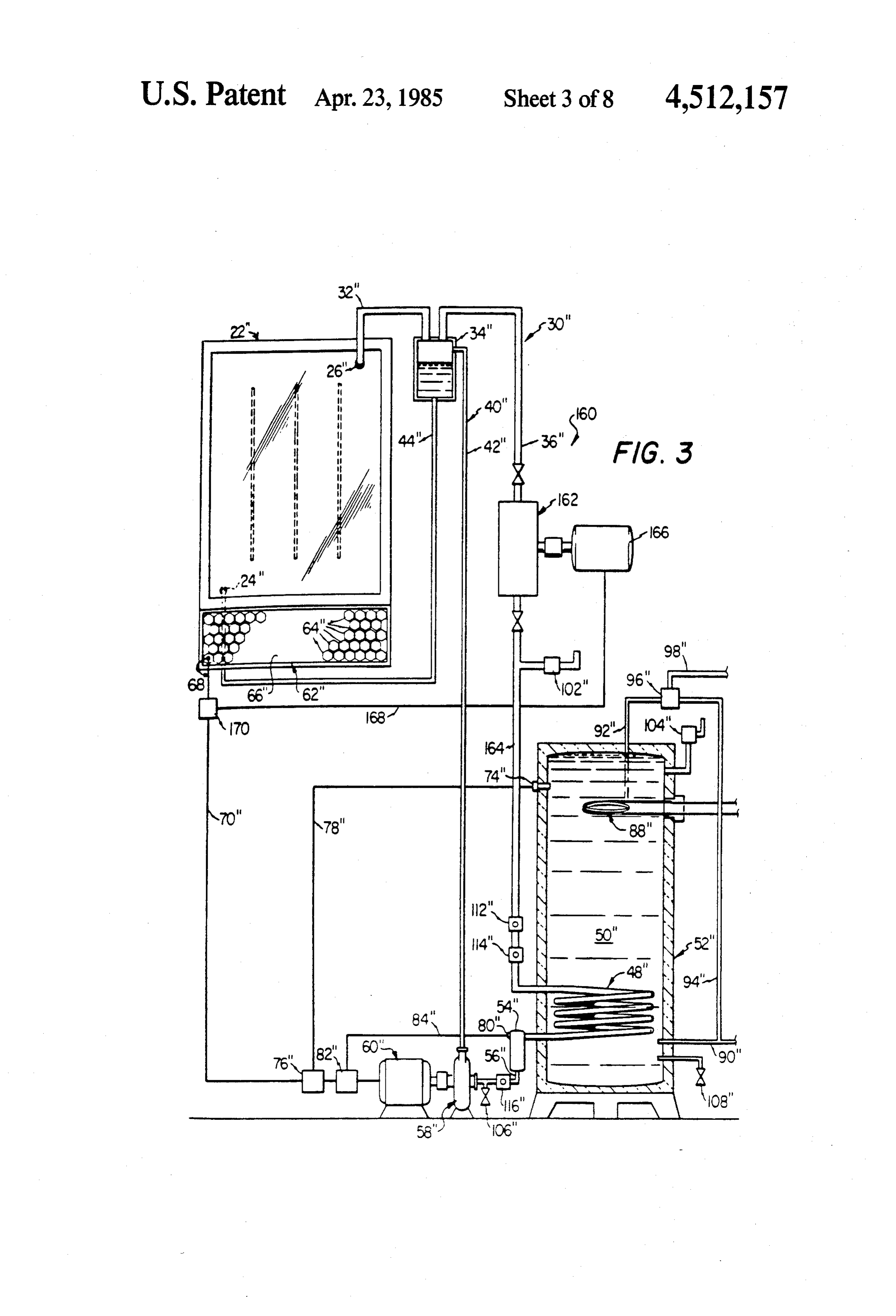
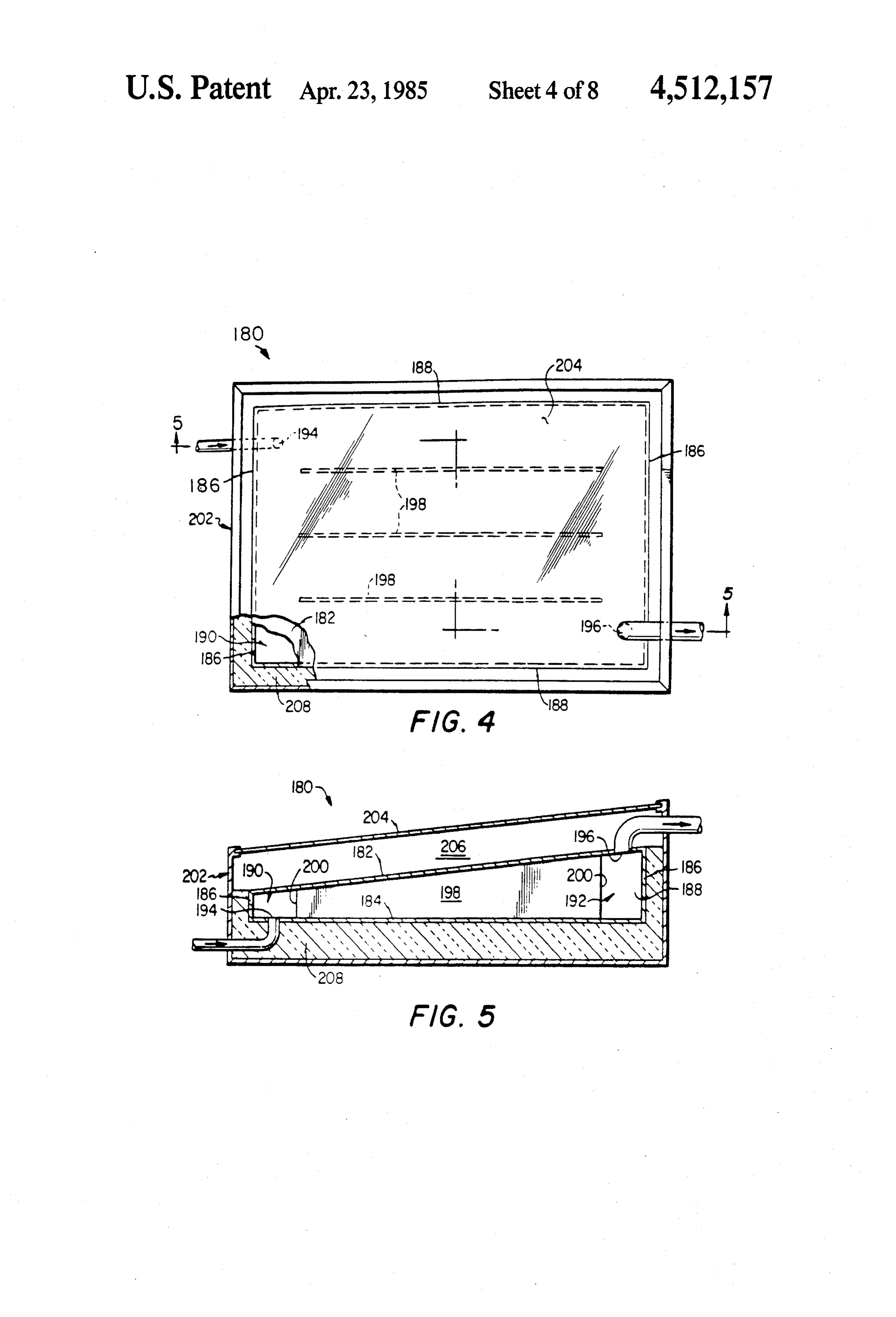
throughout all of the daylight hours. A vapor conduit 30 includes a first portion 32 extend DESCRIPTION OF THE DRAWINGS ing from the outlet 26 of the thermal collector 22 to a separator 34. The separator 34 is illustrated in the draw
A more complete understanding of the invention may 35 ings as a separate vessel, but may in fact comprise part be had by reference to the following Detailed Descrip of the structure of the thermal collector 22, if desired. tion when taken in conjunction with the accompanying The separator 34 receives heated refrigerant from the Drawings, wherein: thermal collector 22 and functions to separate the vapor FIG. 1 is a diagrammatic illustration of a solar pow component of the heated refrigerant from any liquid ered fluid heating system incorporating a first embodi component thereof. The vapor component of the heated ment of the invention; refrigerant flows out of the separator 34 through a sec FIG. 2 is an illustration similar to FIG. 1 showing a ond portion 36 of the vapor conduit 30. second embodiment of the invention; A liquid conduit 40 includes a first portion 42 com FIG. 2a is an enlargement of a portion of the solar prising an inlet to the separator 34 and a second portion powered fluid heating system of FIG. 2; 45 44 comprising an outlet therefrom. If the heated refrig FIG. 3 is an illustration similar to FIG. 1 showing a erant flowing out of the thermal collector 22 has a liquid third embodiment of the invention; component, such liquid component does not flow out of FIG. 4 is a top view of a thermal collector which may the separator 34 through the second portion 36 of the be utilized in any of the embodiments of the invention vapor conduit 30. Instead, any liquid component of the shown in FIGS. 1, 2 or 3; 50 heated refrigerant flows through the separator 34 and FIG. 5 is a sectional view taken along the line 5-5 in through the second portion 44 of the liquid conduit 40 FIG. 4; and is returned thereby to the thermal collector 22 FIG. 6 is a top view of a thermal collector assembly through the inlet 24.
which may be utilized in any of the embodiments of the The vapor component of the heated refrigerant flows invention illustrated in FIGS. 1, 2 or 3; 55 through the second portion 36 of the vapor conduit 30 FIG. 7 is an end view of the thermal collector assem to a condenser 48. The condenser 48 is located in a bly of FIG. 6 in which certain parts have been broken quantity of water 50 which is in turn contained by a tank away more clearly to illustrate certain features of the 52. The condenser 48 transfers heat from the refrigerant invention; to the quantity of water 50 and in so doing returns the FIG. 8 is a diagrammatic illustration of a thermal 60 refrigerant from the vapor phase to the liquid phase. collector assembly which may be utilized in the practice Liquid refrigerant flows out of the condenser 48 into an of the invention; accumulator 54, and out of the accumulator 54 through FIG. 9 is a top view of the thermal collector assembly a third portion 56 of the liquid conduit 40 to a pump 58. of FIG.8; The pump 58 is driven by a motor 60. The pump 58 FIG. 10 is a sectional view taken along the lines 65 functions to receive liquid refrigerant from the con 10-10 in FIG. 9 in the direction of the arrows; denser 48 through the accumulator 54 and to direct FIG. 11 is an enlarged sectional view taken along the pressurized liquid refrigerant through the first portion lines 11-11 in FIG. 10 in the direction of the arrows; 42 of the liquid conduit 40. Liquid refrigerant flowing 12 through the first portion 42 of the liquid conduit 40 valve 106, and the tank has a drain valve 108. The func enters the separator 34 and is then returned to the ther tion of the relief valves 102 and 104 is to automatically mal collector 22 through the second portion 44 of the release excess pressure from the refrigerant circuit and liquid conduit 40 and the inlet 24 of the thermal collec from the tank 52, respectively, and the function of the tor 22. 5 drain valves 106 and 108 is to facilitate the removal of It will thus be understood that the thermal collector refrigerant from the refrigerant circuit and water from 22, the separator 34, the condenser 48 including the the tank 52, respectively.
accumulator 54, the vapor conduit 30 and the liquid The closed refrigerant circuit of the solar powered conduit 40 comprise a closed refrigerant circuit having fluid heating system 20 further includes a pair of upper a predetermined quantity of refrigerant therein. The 10 sight glasses 112 and 114 forming part of the second function of the refrigerant is to receive solar energy by portion 36 of the vapor conduit 30 and a lower sight means of the thermal accumulator 22 and to transfer the glass 116 forming part of the third portion 56 of the received thermal energy to the quantity of water 50 by liquid conduit 40. The function of the sight glasses 112, means of the condenser 48. The function of the pump 58 114 and 116 is to facilitate the filling of the closed refrig is to effect the flow of refrigerant through the closed 15 erant circuit with refrigerant. In each instance the air is refrigerant circuit. first purged from the refrigerant circuit in the conven The solar powered fluid heating system 20 further tional manner.
comprises a photovoltaic collector 62. The photovol Assume first that the temperature of the thermal col taic collector 62 comprises a plurality of photovoltaic lector 22 is higher than that of the quantity of water 50 cells 64 which are mounted in a panel 66. The function 20 in the tank 52. In such a case the upper sight glasses 112 of the photovoltaic collector 62 is to receive solar en and 114 are used to determine the proper refrigerant ergy and to produce an electrical output in response level. Refrigerant is added to the circuit until it is ob thereto. The photovoltaic collector 62 has an output servable in the sight glass 114 but is not observable in terminal 68 which is connected to the motor 60 through the sight glass 112. This assures that the proper quantity a line 70. An external power source may be used to 25 of the refrigerant has been added to the circuit. actuate the motor 60 in lieu of the photovoltaic collec Assume now that the temperature of the quantity of tor 62, if desired. water 50 in the tank 52 is higher than the temperature of A temperature sensor 74 is mounted in the tank 52 the thermal collector 22. In such cases the sight glass and extends into contact with the quantity of water 50 116 is utilized to determine the proper refrigerant level. contained therein. The temperature sensor 74 is con 30 Refrigerant is added to the system until it is observable nected to a switch 76 through a line 78. Whenever the in the sight glass 116. This assures that a proper quantity temperature of the quantity of water 50 in the tank 52 of refrigerant has been added to the circuit. exceeds a preset limit, the temperature sensor 74 actu The operation of the solar powered fluid heating ates the switch 76 to discontinue the flow of electrical system 20 will be readily understood upon consider energy from the photovoltaic collector 62 to the motor 35 ation of three different operating conditions. Assume 60. first that the sun is shining and that hot water is being A float switch 80 is mounted in the accumulator 54. used. Refrigerant is heated in the thermal collector 22, The float switch 80 is connected to a switch 82 through and heated refrigerant flows out of the thermal collec a line 84. The float switch 80 actuates the switch 82 to tor 22 through the outlet 26 and the first portion 32 of discontinue the flow of electrical energy from the pho the vapor conduit to the separator 34. In the separator tovoltaic collector 62 to the motor 60 whenever the 34 the vapor component of the heated refrigerant is liquid refrigerant in the accumulator 54 falls below a separated from any liquid component thereof, and the predetermined level. vapor component of the heated refrigerant then flows The tank 52 is preferably conventional in design and through the second portion 36 of the vapor conduit 30 construction. The tank 52 is preferably either formed 45 to the condenser 48.
from or is surrounded by a thermally insulating material In the condenser 48 heat is transferred from the re to prevent the loss of heat from the quantity of water 50 frigerant to the quantity of water 50 in the tank 52, and contained within the tank 52. The tank 52 is provided the refrigerant is simultaneously returned from the with an auxiliary heating apparatus 88 which functions vapor phase to the liquid phase. Liquid refrigerant to heat the quantity of water 50 whenever insufficient 50 flows out of condenser 48 though the accumulator 54 solar energy is available for such purpose. It will be and through the third portion 56 of the liquid conduit 40 understood that although an electrical auxiliary heating to the pump 58.
apparatus 88 is illustrated in FIG. 1, the auxiliary heat The pump 58 is driven by the motor 60 and functions ing apparatus 88 is entirely conventional in design and to direct pressurized liquid refrigerant through the first may be adapted for actuation by any convenient type of 55 portion 42 of the liquid conduit 40 to the separator 34. fuel. Liquid refrigerant received in the separator 34, either Cold water is received in the tank 52 through an inlet through the first portion 32 of the vapor conduit 30 or line 90. Hot water is withdrawn from the tank 52 through the first portion 42 of the liquid conduit 40, is through a line 92. The line 92 and a line 94 connected to withdrawn from the separator 34 through the second the inlet line 90 both extend to a blending valve 96. The portion 44 of the liquid conduit 30 and is directed to the blending valve 96 combines hot water from the line 92 thermal collector 22 through the inlet 24. At this point and cold water from the line 94 in proper proportions to the foregoing cycle of operation is repeated and is thus prevent delivery of water at a desired temperature continuous in nature.
above a predetermined maximum through an outlet line The pump 58 is driven by the motor 60 which is in 98. 65 turn driven by electrical energy supplied either from The closed refrigerant circuit includes a relief valve the photovoltaic collector 62 through the line 70 or 102, and the tank 52 is provided with a relief valve 104. from an external source. If the temperature of the quan The closed refrigerant circuit further includes a drain tity of water 50 in the tank 52 exceeds a predetermined 13 limit, the temperature sensor 74 actuates the switch 76 ture or pressure levels. If the sun is not shining and hot to interrupt the flow of electrical energy to the motor water is being used the auxiliary heating system 88 60 and operation of the system 20 ceases. Likewise, if automatically functions to maintain the quantity of the accumulator 54 is not full of liquid refrigerant the water 50 within the tank 52 within a predetermined float switch 80 actuates the switch 82 to interrupt the temperature range.
flow of electrical energy to the motor 60 and operation Referring now to FIG. 2, there is shown a solar pow of the system 20 ceases. ered fluid heating system 120 incorporating a second Assume now that the sun is shining but that no hot embodiment of the invention. The system 120 utilizes water is being used. The foregoing cycle of operation numerous component parts which are substantially continues until the temperature of the quantity of water O identical in construction and function to component 50 in the tank 52 reaches a predetermined upper limit. parts of the solar powered fluid heating system 20 illus At this point the temperature sensor 74 actuates the trated in FIG. 1. Such identical component parts are switch 76 to interrupt the flow of electrical energy to designated in FIG. 2 with the same reference numerals the motor 60. Thereafter, liquid refrigerant is no longer utilized in the description of the system 20, but are returned to the separator 34 by the pump 58. 15 differentiated therefrom by means of a prime () desig The thermal collector 22 temporarily continues to nation.
generate heated refrigerant. The vapor component of The primary distinction between the solar powered the heated refrigerant continues to flow to the con fluid heating system 120 of FIG. 2 and the system 20 of denser 48 through the second portion 36 of the liquid FIG. 1 involves the fact that in lieu of the pump 58 and conduit 30. However, liquid refrigerant is not returned 20 the motor 60 of the system 20, the system 120 employs from the condenser 48 to the separator 34, but instead a compressor 122 driven by a motor 124. Compressor accumulates in the condenser 48, in the accumulator 54, 120 receives heated refrigerant vapor from the separa in the third portion 56 of the liquid conduit 40 and in the tor 34 through the second portion 36' of the refrigerant lower part of the first portion 42 of the liquid conduit conduit 30' and directs pressurized refrigerant vapor to 40. 25 the condenser 48' through a third portion 126 of the Eventually all of the refrigerant is exhausted from the vapor conduit 30'.
separator 34 and from the thermal collector 22. There The motor 124 and therefore the compressor 122 is fore, although the system 20 is in the so-called stagna driven by electrical energy supplied from the photovol tion condition, the system 20 cannot reach excessive taic collector 62. Alternatively, the motor 124 and temperature or pressure levels. This is because all of the 30 therefore the compressor 122 is driven by electrical refrigerant is exhausted from the thermal collector 22, energy supplied from a generator 128 through a line whereupon further heating thereof cannot take place. 130. The generator 128 is in turn driven by a windmill The system 20 simply remains in the stagnation condi 132. A switch 134 prevents the backflow of electrical tion until the temperature of the quantity of water 50 in energy from the generator 128 to the photovoltaic col the tank 52 is reduced, whereupon the operating cycle 35 lector 62 through the line 70'. The motor 124 and there of the system 20 is automatically restarted. fore the compressor 122 may be drawn by electrical Assume now that hot water is being withdrawn from energy supplied from an external source, if desired. the tank 52 but that the sun is not shining. In such in Another distinction between the solar powered fluid stances the system 20 does not operate. The refrigerant heating system 120 of FIG. 2 and the system 20 of FIG. in the closed refrigerant circuit then accumulates either 40 1 involves the use of a check valve assembly 136 to in the thermal collector 22 and the separator 34, if the prevent the flow of refrigerant in the vapor phase into temperature of the quantity of water in the tank 52 is the first portion 42 of the liquid conduit 40'. As is best higher than the temperature of the thermal collector 22, shown in FIG. 2a, the check valve assembly 136 in or in the condenser 48, the third portion 56 of the liquid cludes a chamber 140 which receives refrigerant from conduit 40 and the lower part of the first portion 42 of 45 the condenser 48 through an inlet 142 and which dis the liquid conduit 40, if the temperature of the thermal charges refrigerant into the first portion 42 of the liquid collector is higher than that of the quantity of water 50 conduit 40' through an outlet 144. A ball 146 is in the tank 52. In either event the system 20 quickly mounted within the chamber 140.
comes to equilibrium, and any significant flow of refrig The ball 146 has a predetermined density which is erant through the closed refrigerant circuit is discontin SO substantially less than that of the refrigerant in the ued. closed refrigerant circuit of the system 120 when the The fact that the sun is not shining when there is a refrigerant is in the liquid phase and is substantially demand from hot water does not mean that hot water is greater than that of the refrigerant in the closed refrig unavailable from the tank 52. To the contrary, in such erant circuit when the refrigerant is in the vapor phase. circumstances the auxiliary heating apparatus 88 is auto 55 A screen 150 extends across the chamber 140 to limit matically actuated to heat the quantity of water 50 in upward movement of the ball 146 when the chamber the tank to a predetermined temperature range. When 140 is filled with liquid refrigerant. A valve seat 152 is the auxiliary heating apparatus 88 is operating the tank positioned to receive the ball 146 if liquid refrigerant is 52 functions in the manner of a conventional water drained therefrom.
heater. 60 It will be understood that in the normal operation of It will thus be understood that the solar powered the system 120 the chamber 140 is continuously filled fluid heating system 20 comprises a virtually fail safe with liquid refrigerant. The ball 146 therefore normally system for providing hot water. Under normal operat floats upwardly in the chamber 140 with the upward ing conditions the system 20 operates continuously to movement of the ball 146 being limited by the screen heat the quantity of water 50 within the tank 52. If the 65 150. If for any reason liquid refrigerant is drained out of sun is shining but no hot water is being used the system the chamber 140 the ball 146 moves downwardly into 20 eventually discontinues operation, but under circum engagement with the valve seat 152. The ball 146 and stances not involving any danger of excessive tempera the valve seat 152 thereafter cooperate to prevent the 14 discharge of refrigerant in the vapor phase into the or 160 illustrated in FIGS. 1, 2 and 3, respectively. The liquid conduit 40' through the outlet 144. thermal collector assembly 180 includes first and second The operation of the solar powered fluid heating plates 182 and 184 which are preferably formed from system 120 is substantially identical to that of the solar metal. Although illustrated as flat in FIGS. 4 and 5, powered fluid heating system 20. One advantage in the plates 182 and 184 may be strengthened by means of use of the solar powered fluid heating system 120 shown corrugations, if desired. In any event at least the first in FIG. 2 is that the system 120 is capable of operating plate 182 must be formed from a material which is as a heat pump. Under such circumstances the system highly thermally conductive. The outer surface of the 120 is adapted to heat the quantity of water 50' in the first plate 182 is preferably finished utilizing conven tank 52" even though the sun is not shining. 10 tional techniques in such a way as to be highly absor For example, consider a warm, breezy summer eve bent of and therefore highly nonreflective of solar radi ning. Under such circumstances windmill 132 actuates ation.
the generator 128 to produce electrical energy which in A pair of end walls 186 and a pair of side walls 188 turn actuates the motor 124 to drive the compressor extend along the ends and sides of the first and second 122. Heat from the atmosphere vaporizes the refrigerant 15 plates 182 and 184, respectively. The end walls 186 and in the thermal collector 22". The compressor 122 deliv the side walls 188 are secured to the plates 182 and 184 ers the heated refrigerant vapor from the separator 34' for cooperation therewith to define a substantially to the condenser 48", whereby the quantity of water 50' closed refrigerant heating chamber. The first and sec in the tank 52' is heated even though the sun is not ond plates 182 and 184 extend in divergent planes to shining. 20 define a refrigerant receiving zone 190 wherein the Referring now to FIG. 3, there is shown a solar pow plates 182 and 184 are positioned relatively close to one ered fluid heating system 160 incorporating a third another, and a refrigerant discharge zone 192 wherein embodiment of the invention. The system 160 incorpo the plates 182 and 184 are positioned relatively apart rates numerous component parts which are substan from one another. A refrigerant inlet 194 extends to the tially identical in construction and function to the com 25 refrigerant receiving zone 190 of the refrigerant heating ponent parts of the solar powered fluid heating system chamber, and a refrigerant outlet 196 extends from the 20 shown in FIG. 1. Such identical component parts are refrigerant discharge 192 of the refrigerant heating designated in FIG. 3 with the same reference numerals chamber.
utilized hereinabove in the description of the system 20, A plurality of struts 198 are positioned within the but are differentiated therefrom by means of a double 30 refrigerant heating zone of the thermal collector assem prime (") designation. bly 180. Each strut 198 is connected between the first The primary distinction between the solar powered and second plates 182 and 184 and serves to prevent fluid heating system 160 of FIG. 3 and the solar pow both inward and outward movement of the plates rela ered fluid heating system 20 of FIG. 1 relates to the fact tive to each other. The struts 198 extend generally par that the system 160 includes a turbine 162. The turbine 35 allel to and are spaced apart from the side walls 188. 162 receives heated refrigerant vapor from the separa The struts extend to ends 200 which are spaced apart tor 34" and is driven thereby. Refrigerant vapor dis from the end walls 186. The size, shape and positioning charged from the turbine 162 is directed to the con of the struts 198 relative to the side walls 188 and the denser 48" through a third portion 164 of the vapor end walls 186 is selected so as to not impede the flow of conduit 30'. refrigerant throughout the refrigerant heating chamber. Upon actuation by heated refrigerant vapor flowing It will be noted that, except for the negligible area in through the vapor conduit 30", the turbine 162 drives a with the plate 182 engages the struts 198, the entire generator 166. The generator 166 produces an electrical interior surface area of the plate 182 is in contact with output which is directed to the pump 60' through a line refrigerant contained within the refrigerant heating 168 and part of the line 70". A switch 170 prevents 45 chamber. This feature of the thermal collector assembly backflow of electrical energy from the generator 166 to 180 is highly important in that it greatly enhances the the photovoltaic collector 62". flow of solar energy into the thermal collector as com The primary advantage arriving from the use of the pared with prior designs.
system 160 involves the fact that because the turbine The thermal collector assembly 180 further includes a 162 and the generator 166 are incorporated therein, the 50 frame 202. The frame 202 includes a panel 204 overly system 160 may employ a larger thermal collector and a ing the first plate 182. The panel 204 is formed from a smaller photovoltaic collector when compared with the material which is highly transparent to solar radiation, equivalent components of the system 20. During the for example, glass. The panel 204 and the remainder of initial phase of the operation of the system 160, electri the frame 202 define a closed chamber 206 overlying the cal energy for driving the motor 60' and therefore the 55 first plate 182.
pump 58' is supplied from the photovoltaic collector The remainder of the frame 202 may be formed from 62'. However, when the system 160 is in full operation any convenient material, for example, metal, plastic, the thermal collector 22' supplies refrigerant vapor in wood, etc. In certain applications of the thermal collec sufficient quantity both to operate the turbine 162 and to tor assembly 180 it will be desirable to thermally insu heat the quantity of water 50" in the tank 52" by means 60 late the plate 184, the end walls 186 and the side walls of the condenser 48". Under such circumstances electri 188 which cooperate with the plate 182 to define the cal energy for driving the pump 58' is primarily sup refrigerant heating chamber. In such instances a layer of plied by the generator 166 under the actuation of the insulation 208 is provided between the frame 202 and turbine 162. Otherwise, the operation of the system 160 the plate 184, the end walls 186 and the side walls 188. is substantially identical to that of the system 120. 65 In other applications of the thermal collector assem Referring now to FIGS. 4 and 5, there is shown a bly 180 it will be desirable to expose the plate 184 to thermal collector assembly 180 which may be utilized in solar radiation. In such cases the portion of the frame any of the solar powered fluid heating systems 20, 120 202 overlying the panel 184 is formed from a material 15 such as glass and the portion of the layer of insulation assembly 220. This procedure continues until the refrig 208 extending adjacent the panel 184 is omitted. In still erant in the refrigerant heating chamber of the thermal other applications of the thermal collector assembly 180 collector assembly 220 has been heated sufficiently to it will be desirable to expose the plate 184 to the ambient effect vaporization thereof. The refrigerant vapor then atmosphere. In such cases the frame 202 is constructed flows through the outlet 196' of the thermal collector to seal the chamber 206, the layer of insulation 208 is assembly 220 to the separator and from the separator to omitted entirely, and the frame 202 is constructed in an the compressor which in turn directs compressed refrig open configuration to allow the passage of the ambient erant vapor to the condenser of the solar powered fluid atmosphere therethrough. heating system. In this manner the solar powered fluid Referring now to FIGS. 6 and 7, there is shown a 10 heating system is adapted to produce hot water even at thermal collector assembly 220 which may be utilized in temperatures substantially below the vaporization tem any of the solar powered fluid heating systems 20, 120 perature of the refrigerant in the primary refrigerant or 160 shown in FIGS. 1, 2 and 3, respectively. The circuit thereof, thermal collector assembly 220 incorporates numerous The heat dissipating assembly 224 comprises an evap component parts which are substantially identical to 15 orator 240 positioned within the refrigerant discharge component parts of the thermal collector assembly 180 zone 192 of the thermal collector assembly 220. A shown in FIGS. 4 and 5. Such identical component condenser 242 is adapted to discharge heat to the ambi parts are designated in FIGS. 6 and 7 with the same ent atmosphere. To this end, the condenser 242 is pro reference numerals utilized hereinabove in the descrip vided with a plurality of heat dissipating fins 244. Other tion of the thermal collector assembly 180, but are dif 20 conventional techniques for maximizing exposure of the ferentiated therefrom by means of a prime () designa condenser 242 to the ambient atmosphere may be uti tion. lized in the practice of the invention if desired. A refrig The thermal collector assembly 220 differs from the erant conduit 246 includes a first portion 248 extending thermal collector 180 in that it incorporates a preheater from the evaporator 240 to the condenser 242 and a assembly 222 and a heat dissipating assembly 224. As 25 second portion 250 extending from the condenser 242 to will be appreciated by those skilled in the art, the pre the evaporator 240.
heater assembly 222 may be utilized with or without the The heat dissipating assembly 224 is charged with the heat dissipating assembly 224, and vice versa. That is, refrigerant having a substantially higher boiling point although the preheater assembly 222 and the heat dissi than the boiling point of the refrigerant in the refriger pating assembly 224 are illustrated in conjunction with 30 ant heating chamber of the thermal collector assembly the same thermal collector assembly 220, the two as 220. As will be appreciated, certain operating condi semblies are actually entirely distinct from each other, tions of a solar powered fluid heating system can occur both in construction and in function. in which the temperature within the thermal collector The preheating assembly 222 includes an evaporator assembly of the system rises significantly. In any such 226 adapted to receive heat from the ambient atmo 35 instance the refrigerant in the evaporator 240 is vapor sphere. To this end, the evaporator 226 may be pro ized. The refrigerant vapor then flows into the con vided with a plurality of fins 228. Other conventional denser 242, whereupon heat is removed from the refrig techniques for enhancing the exposure of the evapora erant and is discharged into the ambient atmosphere. In tor 226 to the ambient atmosphere may be utilized in the this manner protection against excessive temperature practice of the invention, if desired. The assembly 226 within the refrigerant heating chamber of the thermal further includes a condenser 230 positioned in the re collector assembly 220 is assured.
frigerant heating chamber of the thermal collector as A thermal collector assembly 260 constructed in ac sembly 220, and specifically in the refrigerant receiving cordance with the invention is diagrammatically illus zone 190 thereof. A refrigerant conduit 232 includes a trated in FIG. 8. The thermal collector assembly 260 first portion 234 extending from the evaporator 226 to 45 includes first and second plates 262 and 264 each formed the condenser 230 and a second portion 236 extending from a thermally conductive material. The plates 262 from the condenser 230 to the evaporator 226. and 264 may be corrugated for strength, if desired. The The preheater assembly 222 is particularly adapted first and second plates 262 and 264 define a refrigerant for use in conjunction with embodiments of the inven heating chamber therebetween. The plates 262 and 264 tion such as that shown in FIG. 2 wherein a compressor 50 extend in divergent planes to define a refrigerant receiv is utilized to receive refrigerant vapor from the separa ing zone 266 wherein the plates 262 and 264 are posi tor and to direct pressurized refrigerant vapor to the tioned relatively close to one another and a refrigerant condenser. In such instances the preheater assembly 222 discharge zone 268 wherein the plates 262 and 264 are is preferably charged with a refrigerant having a sub positioned relatively apart from each other. stantially lower boiling point than the boiling point of 55 A frame 270 supports the plates 262 and 264 and the the refrigerant in the refrigerant heating chamber of the refrigerant heating zone defined therebetween on the thermal collector assembly 220. The refrigerant in the surface 272 of a roof. The frame 270 supports the plate preheater assembly 222 is therefore adapted for vapori 264 in a spaced apart relationship with respect to the zation in the evaporator 226 at temperatures substan roof surface 272. The frame 270 includes a plate 274 tially below the boiling point of the refrigerant in the 60 which is transparent to solar radiation. The plates 274 refrigerant heating chamber of the thermal collector together with other components of the frame 270 form assembly 220, and regardless of whether or not the sun a closed chamber 276 surrounding the plate 262 of the is shining. thermal collector assembly 260. Refrigerant vapor flows from the evaporator 226 A third plate 278 formed from a thermally insulating through the refrigerant conduit 232 to the condenser 65 material is positioned within the refrigerant heating 230, wherein heat is transferred from the refrigerant ofZone between the first and second plates 262 and 264. the preheater assembly 222 to the refrigerant within theThe third plate 278 is positioned substantially equidis refrigerant heating chamber of the thermal collector tant from the first and second plates 262 and 264, and 16 extends the entire distance between the refrigerant re ing structure 340 for preventing relative movement ceiving zone 266 and the refrigerant discharge zone 268. between the erect portion 336 and the prone portion 334 The third plate 278 divides the refrigerant heating of the frame. For example, the bracing structure 340 chamber into an upper refrigerant path 280 extending may comprise cables 342 secured to suitable fasteners adjacent the first plate 262 and the second refrigerant 344, etc.
path 282 extending adjacent the second plate 264. Re The prone portion 334 of the frame 332 includes a frigerant in the first refrigerant path 280 is adapted for first support surface 346, and the erect portion 336 of heating by solar radiation which passes through the the frame includes a second support surface 348. The plate 274 of the frame 270 and through the first plate 262 second support surface 348 extends perpendicularly to heat the refrigerant in the first refrigerant path. Re O with respect to the first support surface 346. The erect frigerant in the second refrigerant path 282 is adapted to portion 336 of the frame further includes a third support receive heat from the ambient atmosphere through the surface 350 which extends parallel to but which faces in second plate 264. Thus, the thermal collector assembly the opposite direction from the second support surface 260 is adapted to produce refrigerant vapor either when 348. The prone portion of the frame 334 further includes the sun is shining or when the temperature of the sur a fourth support surface 352 which extends parallel to, rounding atmosphere is sufficiently high to vaporize the and preferably comprises an extension of the first sup refrigerant in the refrigerant heating chamber thereof. port surface 356.
Heated refrigerant flows from the thermal collector The photovoltaic cell assembly 330 further comprises assembly 260 through a vapor conduit 288 including a a first array of photovoltaic cells 356 mounted on the first portion 290 extending from the refrigerant dis 20 first support surface 346; a second array of photovoltaic charge zone 268 of the thermal collector assembly 260 cells 358 mounted on the second support surface 348; a to a separator 292 and a second portion 294 extending third array of photovoltaic from the separator 292 to a condenser (not shown). third support surface 350 andcells 360 mounted on the Liquid refrigerant is returned to the thermal collector voltaic cells 362 mounted on the fourth array a fourth of photo support surface assembly 260 from the condenser through a liquid con 352. The arrays of photovoltaic cells 356, 358, 360 duit 298 including a first portion 300 extending from the 362 are each mounted in a frame 364, and the frames and364 condenser to the separator 292 and a second portion 302 extending from the separator 292 to the refrigerant are secured to the frame 332 by means of suitable fasten receiving zone. 266 of the thermal collector assembly ers 366. Each of the arrays of photovoltaic cells 356, 260. It will thus be understood that the thermal collec 30 358, 360 and 362 produces an output, and the outputs of the arrays of photovoltaic cells are added together to tor assembly 260 is adapted for use with any of the solar produce powered fluid heating systems 20, 120 or 160 shown in throughouta the combined output which is optimized entire day.
FIGS. 1, 2 and 3, respectively. Operation of the photovoltaic cell assembly 330 will The structural detail of the thermal collector assem bly are illustrated in FIGS. 9, 10 and 11. The frame 270 35 be best understood by consideration of the positioning includes legs 304 which support the plate 264 above the of the sun at various times during the day. At dawn the underlying surface 272. The plates 262 and 264 may position of the sun relative to the assembly 330 is repre comprise part of an elongate plate 306 which is bent sented by the arrow 370. At such time the array of around a suitable form to provide curved end portions photovoltaic cells 360 is positioned directly in the path 308 and 310. The ends of the plate 306 are overlapped at of the rays of the sun, while the remaining photo cell a convenient location 312 and are welded or brazed arrays comprised in the assembly 330 are positioned together. The refrigerant heating chamber of the ther substantially out of the path of the rays of the sun. At mal collector assembly 260 is then closed by side plates mid-morning the sun is positioned as represented by the 314 extending along and joined to the opposite edges of arrow 372. At such time the photovoltaic cell arrays the plate 306. 45 360 and 362 are positioned for combined maximum The third plate 278 of the thermal collector assembly exposure to the rays of the sun, while the photovoltaic 260 preferably comprises part of a third plate/strut cell arrays 356 and 358 are positioned substantially out assembly 320. As is best shown in FIG. 11, in addition to of the path of the rays of the sun. At mid-day the posi the third plate portion 278, the third plate/strut assem tion of the sun is represented by the arrow 374. At such bly 320 includes a plurality of strut portions 322 each 50 time the photovoltaic cell array 356 and 362 are posi extending outwardly from the third plate portion 278 tioned for maximum exposure to the rays of the sun, into engagement with the interior surfaces of the plates while the photovoltaic cell arrays 358 and 360 are posi 262 and 264. The third plate/strut assembly 320 further tioned substantially out of the path of the rays of the includes a plurality of fasteners 324 each extending sun. At mid-afternoon the position of the sun is repre through the plates 262 and 264 and through one of the 55 sented by the arrow 376. At such time the photovoltaic strut portions 322. By means of the strut portions 322 cell arrays 356 and 358 are positioned for combined and the fasteners 324 the third plate/strut assembly 320 maximum exposure to the rays of the sun, while the serves to prevent both inward and outward movement photovoltaic cell arrays 360 and 362 are substantially of the plates 262 and 264 relative to one another. non-exposed to the rays of the sun. At dusk the position FIG. 12 illustrates a photovoltaic cell assembly 330 of the sun is represented by the arrow 378. At such time which may be utilized in conjunction with any of the the photovoltaic cell 358 is positioned for maximum solar powered fluid heating systems 20, 120 or 160 illus exposure to the rays of the sun, while the remaining trated in FIGS. 1, 2 and 3. The photovoltaic cell assem photovoltaic cell arrays are not significantly exposed bly 330 includes a frame 332 including a prone portion thereto. It will thus be understood that by adding the 334 and an erect portion 336. The erect 336 is preferably 65 outputs of the photovoltaic cell arrays 356,358, 360 and secured to the prone portion 334 by means of fasteners 362 the photovoltaic cell assembly 330 produces a com 338 to facilitate disassembly of the frame 332 for ship bined output which is optimized throughout all of the ping, etc. The frame 332 further includes suitable brac daylight hours.
Page 17scan →
FIGS. 13 and 14 illustrate a thermal collector assen Although preferred embodiments of the invention bly 390 which may be utilized in any of the solar pow have been illustrated in the accompanying Drawings ered fluid heating systems 20, 120 or 160 illustrated in and described in the foregoing Detailed Description, it FIGS. 1, 2 and 3, respectively. The thermal collector will be understood that the invention is not limited to assembly 390 comprises three thermal collectors 392, the embodiments disclosed, but is capable of numerous 394 and 396. The three thermal collectors 392,394 and rearrangements, modifications, and substitutions of 396 receive liquid refrigerant from a common inlet con parts and elements without departing from the spirit of duit 398 and are connected thereto through isolation the invention.
valves 400. The three thermal collectors 392, 394 and I claim:
396 discharge heated refrigerant through a common 10 1. A solar powered water heating system comprising: outlet conduit 402 and are connected therethrough to a predetermined quantity of refrigerant; isolation valves 404. The use of the isolation valves 400 a thermal collector for heating the refrigerant; and 404 permits any of the thermal collectors to be separator means for receiving the heated refrigerant disconnected from the refrigerant circuit to facilitate 15 from the thermal collector and for separating the repair, etc. vapor component from any liquid component of The thermal collectors 392,394 and 396 are prefera the heated refrigerant;
bly constructed as shown in FIGS. 4 and 5. The teach a tank having a predetermined quantity of water ings of drawing FIGS. 6through 11 may also be utilized therein;
in the construction of the thermal collectors comprising 20 a condenser positioned within the tank for receiving the assembly 390, if desired. However, as is best shown the vapor component of the heated refrigerant in FIG. 14, the thermal collector 394 has a second plate from the separator means and for transferring heat 406 which is exposed to solar radiation through a panel from the refrigerant to the water in the tank and 408 formed from a material which is transparent to solar thereby returning the refrigerant vapor to the liq radiation, for example, glass. uid phase;
The operation of the thermal collector assembly 390 25 vapor conduit means extending from the separator will be best understood by consideration of the position means to the condenser;
of the sun at various times during the day. At dawn, the liquid conduit means extending from the condenser to sun is positioned as represented by the arrow 410, and the separator means and from the separator means to the thermal collector;
the thermal collector 394 is thus positioned for maxi 30 said thermal collector, separator means, condenser, mum exposure to the rays of the sun. At mid-morning vapor conduit means and liquid conduit means the sun is positioned as represented by the arrow 412, comprising a closed refrigerant circuit which con and the thermal collectors 394 and 396 are positioned tains the predetermined quantity of refrigerant; for combined maximum exposure to the rays of the sun. refrigerant pressurizing means for causing the refrig At mid-day the sun is positioned as represented by the 35 erant to flow through the closed refrigerant circuit; arrow 414, and the thermal collectors 392 and 396 are and positioned for maximum exposure to the rays of the sun. solar powered means for actuating the refrigerant At mid-afternoon the sun is positioned as represented by pressurizing means which comprises a turbine the arrow 416, and the thermal collectors 392 and 394 driven by refrigerant vapor flowing through the are positioned for combined maximum exposure to the 40 vapor conduit means from the separator means to rays of the sun. At dusk the sun is positioned as repre the condenser, and a generator driven by the tur sented by the arrow 418, and the thermal collector 394 bine.
is once again positioned for maximum exposure to the 2. The solar powered water heating system according rays of the sun. Since the outputs of the thermal collec to claim 1 wherein the refrigerant pressurizing means tors 392,394 and 396 are added together, it will thus be 45 comprises a pump for receiving liquid refrigerant from understood that the thermal collector assembly 390 the condenser and for directing pressurized liquid re produces a combined output which is optimized frigerant to the separator means through part of the throughout all of the daylight hours. liquid conduit means and a motor for driving the pump, FIG. 15 illustrates a thermal collector assembly 420. and wherein the solar powered means further comprises Many of the component parts of the thermal collector 50 a plurality of photovoltaic cells and means for connect assembly 420 are substantially identical in construction ing the output of the photovoltaic cells to the motor and and function to component parts of the thermal collec thereby driving the pump.
tor assembly 390 illustrated in FIGS. 13 and 14. Such 3. A solar powered fluid heating system comprising: identical component parts are identified in FIG. 15 with a predetermined quantity of refrigerant; the same reference numerals utilized hereinabove in the 55 a thermal collector for heating the refrigerant; description of the thermal collector assembly 390, but separator means for receiving heated refrigerant from are differentiated therefrom by means of a prime () the thermal collector and for separating vapor designation. component from any liquid component of the The primary distinction between the thermal collec heated refrigerant;
tor assembly 390 and thermal collector assembly 420 60 a condenser for receiving the vapor component of the comprises the fact that as opposed to a single upright heated refrigerant from the separator means; thermal collector 394, the thermal collector assembly a supply of fluid to be heated; 420 employs dual upright thermal collectors 424 and means for transferring heat from the refrigerant in the 426. The collectors 424 and 426 are separated by layers condenser to the fluid and thereby returning the of thermally insulative material 428. Otherwise, the 65 refrigerant vapor to the liquid phase; construction and operation of the thermal collector vapor conduit means extending from the thermal assembly 420 is identical to that described above in collector to the separator means and from the sepa connection with the thermal collector assembly 390. rator means to the condenser;
Page 18scan →
liquid conduit means extending from the condenser to end panels extending along the opposite ends of the first the thermal collector; and second panels, respectively.
said thermal collector, separator means, condenser, 10. The thermal collector according to claim 8 vapor conduit means and liquid conduit means wherein the baffle means comprises a plate extending comprising a closed refrigerant circuit which con between and connected to the first and second panels, tains the predetermined quantity of refrigerant; said plate extending parallel to the side panels and hav refrigerant pressurizing means for causing the refrig ing opposite ends each positioned in a substantially erant to flow through the closed refrigerant circuit; spaced apart relationship with respect to one of the end and panels.
solar powered means for actuating the refrigerant O 11. The thermal collector according to claim 8 fur pressurizing means which comprises a turbine ther including a layer of insulating material extending driven by refrigerant vapor flowing through the adjacent to the second panel, the side panels and the end vapor conduit means from the separator means to panels for retaining heat within the refrigerant heating the condenser and a generator driven by the tur chamber.
bine. 15 12. The thermal collector according to claim 8 fur 4. The solar powered fluid heating system according ther characterized by a plate formed from a material to claim 3 wherein the refrigerant pressurizing means that is substantially transparent to solar radiation and comprises a pump receiving liquid refrigerant from the means supporting the plate in an overlying and substan condenser and for directing pressurized liquid refriger tially parallel relationship with respect to the first panel. ant through at least part of the liquid conduit means and 20 13. The thermal collector according to claim 12 fur a motor for driving the pump. ther including means extending between the first panel 5. The solar powered fluid heating system according and the plate for forming a closed chamber therebe to claim 3 wherein the solar powered means for actuat tween.
ing the refrigerant pressurizing means further comprises 14. The thermal collector according to claim 13 a plurality of photovoltaic cells and means connecting 25 wherein the plate is formed from glass and the first and the output of the photovoltaic cells to the motor and second panels are formed from metal. thereby driving the pump. 15. The thermal collector according to claim 14 6. The solar powered fluid heating system according wherein the baffle means further comprises a plurality to claim 3 wherein the liquid conduit means includes a of spaced apart plates each extending substantially par first portion extending from the condenser to the sepa 30 allel to the side walls and each having ends positioned rator means and a second portion extending from the substantially spaced apart from the end walls of the separator means to the thermal collector so that separa refrigerant heating chamber.
tor means is included both in the vapor conduit means 16. In a solar powered fluid heating system, a thermal and the liquid conduit means, collector comprising:
7. The solar powered fluid heating system according 35 first and second spaced apart panels, at least the first to claim 3 further including means for preventing refrig panel being formed from a thermally conductive erant vapor from entering the liquid conduit means material;
from the condenser. connector panel means extending between and con 8. In a solar powered fluid heating system, a thermal nected to the first and second panels for coopera collector comprising: tion therewith to define a substantially closed re first and second spaced apart panels, at least the first frigerant heating chamber; panel being formed from a thermally conductive said first panel being exposed to solar radiation over material; substantially all of its exterior surface and being in connector panel means extending between and con contact with refrigerant in the refrigerant heating nected to the first and second panels for coopera 45 chamber over substantially all of its interior sur tion therewith to define a substantially closed re face;
frigerant heating chamber; inlet means for admitting liquid refrigerant to the said first panel being exposed to solar radiation over refrigerant heating chamber; substantially all of its exterior surface and being in outlet means for exhausting vapor refrigerant from contact with refrigerant in the refrigerant heating 50 the refrigerant heating chamber; chamber over substantially all of its interior sur baffle means positioned within the refrigerant heating face; chamber and connected between the first and sec inlet means for admitting liquid refrigerant to the ond panels for preventing both inward and out refrigerant heating chamber; ward relative movement therebetween; outlet means for exhausting vapor refrigerant from 55 said baffle means being spaced apart from the connec the refrigerant heating chamber; and tor panels so as to not impede refrigerant flow baffle means positioned within the refrigerant heating through the refrigerant heating chambers; chamber and connected between the first and sec the first and second panels being substantially rectan ond panels for preventing both inward and out gular;
ward relative movement therebetween; the connector panel means comprising side walls and said baffle means being spaced apart from the connec end walls extending along and connected to the tor panels so as to not impede refrigerant flow sides and the ends of the first and second panels, through the refrigerant heating chamber. respectively;
9. The thermal collector according to claim 8 the baffle means comprising at least one panel extend wherein the first and second panels are rectangular in 65 ing between and connected to the first and second configuration, and wherein the connector panel means panels, said plate extending substantially parallel to comprises a pair of side panels extending along the the side walls and having opposite ends positioned opposite sides of the first and second panels and a pair of in spaced apart relationships to the end walls;
Page 19scan →
a layer of thermally insulating material extending 21. The solar powered fluid heating system according adjacent the second panel and the side and end to claim 17 wherein the refrigerant pressurizing means walls for retaining heat within the refrigerant heat comprises a pump for receiving liquid refrigerant from ing chambers; the first condenser and for directing liquid refrigerant a panel formed from a material substantially transpar through a portion of the liquid conduit means. ent to solar radiation; and 22. The solar powered fluid heating system according means supporting the panel in an overlying and sub to claim 17 wherein the refrigerant pressurizing means stantially parallel relationship with respect to the comprises a compressor for receiving refrigerant vapor first panel and forming a substantially closed cham from the separator means and for directing pressurized ber therebetween. O refrigerant vapor through a portion of the vapor con 17. A solar powered fluid heating system comprising: duit means to the first condenser.
a predetermined quantity of refrigerant; 23. The solar powered fluid heating system according a thermal collector for heating the refrigerant and to claim 17 wherein the refrigerant pressurizing means including: comprises a pump for receiving liquid refrigerant from (a) first and second spaced apart planar panels, at 15 the first condenser and for directing pressurized liquid least the first panel being formed from a ther refrigerant through a portion of the liquid conduit mally conductive material; means and a motor for driving the pump, and further (b) connector panel means extending between and including a plurality of photovoltaic cells and means connected to the first and second panel for coop connecting the output of the photovoltaic cells to the eration therewith to define a substantially closed 20 motor for driving the pump.
refrigerant heating chamber;
(c) said first plate being exposed to solar radiation to 24. The solar powered fluid heating system according claim 17 wherein the refrigerant pressurizing means over substantially all of its exterior surface and being in contact with refrigerant in the refriger comprises a pump for receiving liquid refrigerant from ant heating chamber are substantially all of its 25 refrigerant throughand the first condenser for directing pressurized liquid portion of the liquid conduit interior surface; means and a motor for driving the pump, and further (d) inlet means for admitting liquid refrigerant to including a turbine driven by refrigerant vapor flowing the refrigerant heating chamber; through the vapor conduit means from the separator (e) outlet means for exhausting vapor refrigerant means to the first condenser, a generator driven by the from the refrigerant heating chamber; and turbine, and means connecting the output of the genera (f) baffle means positioned within the refrigerant tor to the motor for driving the pump. heating chamber and connected between the first 25. The solar powered fluid heating system according and second panels for preventing both inward and outward movement therebetween; to claim 17 wherein the refrigerant pressurizing means (g) said baffle means being spaced apart from the 35 comprises a pump for receiving liquid refrigerant from connector panel means to facilitate refrigerant arefrigerant first condenser and for directing pressurized liquid through a portion of the liquid conduit flow through the refrigerant heating chamber;
separator means for receiving heated refrigerant from means and a motor for driving the pump, and further the thermal collector and for separating the vapor including a plurality of photovoltaic cells, a turbine component of the heated refrigerant from any liq 40 driven by refrigerant vapor flowing through the vapor uid component thereof; conduit means from the separator means to the first a condenser for receiving the vapor component of the condenser, a generator driven by the turbine, and means heated refrigerant from the separator means; connecting the output of the photovoltaic cells and the a supply of fluid to be heated; generator to the motor for driving the pump. means for transferring heat from the refrigerant in the 45 26. The solar powered fluid heating system according condenser to the fluid and thereby returning the to claim 17 wherein the refrigerant pressurizing means refrigerant vapor to the liquid phase; comprises a compressor for receiving refrigerant vapor vapor conduit means extending from the separator from the separator means and for directing pressurized means to the condenser; refrigerant vapor through a portion of the vapor con liquid conduit means extending from the condenser to 50 duit means to the first condenser and a motor for driv the inlet means of the thermal collector; ing the compressor, and further including the plurality said thermal collector, separator means, condenser, of photovoltaic cells and means connecting the output vapor conduit means and liquid conduit means of the photovoltaic cells to the motor for driving the comprising a closed refrigerant circuit which con compressor.
tains the predetermined quantity of refrigerant; and 55 27. The solar powered fluid heating system according refrigerant pressurizing means for causing the refrig to claim 17 further including a tank, wherein the fluid to erant to flow through the closed refrigerant circuit. be heated comprises a quantity of water contained in the 18. The solar powered fluid heating system according tank, wherein the first condenser is positioned within to claim 17 further comprising solar powered means for the tank for heating the water contained therein. actuating the refrigerant pressurizing means. 60 28. The solar powered fluid heating system according 19. The solar powered fluid heating system according to claim 17 further including check valve means for to claim 18 wherein the solar powered means comprises preventing the entry of first refrigerant vapor into the a plurality of photovoltaic cells. liquid conduit means.
20. The solar powered fluid heating system according 29. The solar powered fluid heating system according to claim 18 wherein the solar powered means comprises 65 to claim 28 wherein the check valve means comprises: a turbine driven by refrigerant vapor flowing from the a closed chamber having an inlet connected to the separator means to the first condenser through a portion outlet of the first condenser and having an outlet of the vapor conduit means. connected to the liquid conduit means;
Page 20scan →
a ball mounted within the chamber and having a condenser, a generator driven by the turbine, and means predetermined density which is substantially connecting the output of the generator to the motor for greater than the density of first refrigerant vapor driving the pump.
and substantially less than the density of the first 34. The solar powered fluid heating system according refrigerant liquid; - to claim 31 wherein the refrigerant pressurizing means means for limiting upward movement of the ball in comprises a pump and a motor for driving the pump and the chamber when the chamber is filled with first wherein the solar powered means for actuating the refrigerant liquid; and refrigerant pressurizing means comprises a plurality of a valve seat for receiving the ball and thereby closing photovoltaic cells, a turbine driven by refrigerant vapor the inlet to the liquid conduit means when the 10 flowing through the vapor conduit means from the chamber is filled with first refrigerant vapor. separator means to the first condenser, a generator 30. The solar powered fluid heating system according driven by the turbine, and means connecting the outputs to claim 17 wherein the liquid conduit means includes of the photovoltaic cells and the generator to the motor the first portion extending from the condenser to the for driving the pump.
separator means and a second portion extending from 15 35. The solar powered fluid heating system according the separator means to the thermal collector so that the to claim 31 wherein the refrigerant pressurizing means separator means is included both in the vapor conduit comprises a compressor for receiving refrigerant vapor means and in the liquid conduit means. from the separator means and for directing pressurized 31. The solar powered fluid heating system according refrigerant vapor through a portion of the vapor con to claim 30 further including solar powered means for 20 duit means to the first condenser and a motor for driv actuating the refrigerant pressurizing means. ing the compressor, and wherein the solar powered 32. The solar powered fluid heating system according means for actuating the refrigerant pressurizing means to claim 31 wherein the refrigerant pressurizing means comprises a plurality of photovoltaic cells and means comprises a pump and a motor for driving the pump, connecting the output of the photovoltaic cells to the and wherein the solar powered means for actuating the 25 motor for driving the compressor. refrigerant pressurizing means comprises a plurality of 36. The solar powered fluid heating system according photovoltaic cells and means connecting the output of to claim 30 further including a tank, wherein the fluid to the photovoltaic cells to the motor for driving the be heated comprises a quantity of water contained pump. within the tank, wherein the condenser is positioned 33. The solar powered fluid heating system according 30 within the tank for heating the quantity of water to claim 31 wherein the refrigerant pressurizing means therein.
comprises a pump and a motor for driving the pump and 37. The solar powered fluid heating system according wherein the solar powered means for actuating the to claim 30 further including check valve means for refrigerant pressurizing means comprises a turbine preventing the flow of first refrigerant vapor from the driven by refrigerant vapor flowing through the vapor 35 first condenser into the liquid conduit means. conduit means from the separator means to the first k k k
Provenance
- Collection
- Patents citing this work
- Pages
- 20
- Method
- pdftotext (the PDF's own text layer) + pdftoppm 300dpi page scans
- Patent office record
- patents.google.com →
- Source
- Google Patents citing-documents table
- Assignee
- Wetzel Enterprises, Inc.
- Published
- 1985-04-23
- Transcribed from
- patentimages.storage.googleapis.com →