

patent · US4335578A
Solar power converter with pool boiling receiver and integral heat exchanger
22 June 1982
Text
Page 1bibliographic recordscan →
United States Patent (19)
Osborn et al.
54 SOLAR POWER CONVERTER WITH POOL
BOILNG RECEIVER AND INTEGRAL, HEAT
EXCHANGER
(75) Inventors: Douglas B. Osborn; Robert L. Pons, both of Mission Viejo, Calif.
Assignee: Ford Aerospace & Communications
Corporation, Detroit, Mich.
51 Int. Cl. ................................................ F03G 7/02 52 U.S.C. ................................... 60/641.8; 126/418;
Field of Search ........... ... 60/641.8, 641.15, 641.11;
1969,839 8/1934 Goddard ............................. 126/439 4,033,118 7/1977 Powell ............................ 126/439 X 4,068,474 1/1978 Dimitrof........................... 60/641.15 4,222,367 9/1980 Jubb .................................... 126/419 4,252,107 2/1981 Horton ............................ 126/433 X 4,285,333 8/1981 Tanaka et al. ...................... 126/433 Primary Examiner-Allen M. Ostrager
Assistant Examiner-Stephen F. Husar
Attorney, Agent, or Firm-Edward J. Radio; Clifford L. Sadler; Robert D. Sanborn
A solar converter is disclosed which has particular applicability at the focal point of a parabolic concentra tor. The converter absorbs solar thermal radiation in a cavity type receiver and transports the heat via a sec ondary fluid to a heat exchanger which contains a pri mary (i.e., working) fluid used for process heating or to power a heat engine employing either Stirling, Rankine, or Brayton thermodynamic cycles. The secondary fluid is boiled within the receiver by the trapped solar radia tion and the released vapor rises along an elevated path to the heat exchanger. The vapor condenses on the surfaces of the heat exchanger, thereby transferring heat to the engine working fluid. The condensed liquid then flows by means of gravity back to the solar re ceiver. The walls of the cavity receiver are typically comprised of two concentric cylinders joined at one end in a half toroid and at the other end in concentric half spheres. Optimum primary and secondary fluids, which may be different from each other and are differ ent for different applications, are described.
10 Claims, 3 Drawing Figures
Drawings
Page 2drawing sheetscan →
Page 3drawing sheetscan →
Page 4drawing sheetscan →
Page 5scan →
faces of the heat exchanger and transfers heat to a pri
SOLAR POWER CONVERTER WITH POOL mary fluid circulating through the heat exchanger. This BOLING RECEIVER AND INTEGRAL, HEAT primary fluid can be used directly in an industrial pro EXCHANGER . cess heat application or it can be used as the working fluid in a heat engine, employing either the Stirling,
BACKGROUND OF THE INVENTION Rankine or Brayton thermodynamic cycles. In either 1. Field of the Invention case the primary fluid flow rate is adjusted by means of This invention is a solar power converter comprising a simple temperature control, to remove energy from a solar receiver and a heat exchanger. The device col 10 the heat exchanger at the same rate as that of the incom lects concentrated solar radiation in the form of heat ing solar radiation trapped within the receiver. By this and transports same to a device which may effectively means both the primary and secondary working fluids utilize it, such as a heat engine, via a fluid which are held at constant temperature despite wide variations changes state at the solar receiver and again at the heat in solar intensity as a function of time. exchanger. After condensing on the heat exchanger surfaces, the 2. Description of the Prior Art 15 secondary fluid returns in liquid form, by gravity, to the U.S. Pat. No. 4,116,222 shows a solar energy collec boiling pool within the receiver to repeat the energy tion system having a reservoir which in some sense may exchange process. In undergoing phase change, the be considered to be a heat exchanger. Unlike the present secondary fluid transfers heat at very high rates at invention, (1) the heat exchanger has a third fluid, used 20 nearly constant temperature, thereby minimizing en mainly for storage purposes, which results in energy ergy loss between the receiver and the heat exchanger. loss; (2) the patent utilizes forced convection (i.e., a In addition, the very high heat transfer rate and corre pump) to move its secondary fluid; and (3) the second spondingly low wall/fluid temperature differences usu ary fluid does not change state from a liquid to a gas. ally associated with boiling permit a high safety factor U.S. Pat. No. 4,003,367 is a water-to-water solar when compared with the peak solar flux typically expe heater. The secondary water (that which is heated by rienced in cavity receivers. This means that large spatial the sun), is not vaporized as in the present invention; it and/or temporal variations in solar flux result in only is moved through the system by means of the principle small changes in wall temperatures. The high heat that heat rises, setting up a current in the water.
U.S. Pat. No. 4,083,490 is a solar heating system uti transfer rates additionally result in less required surface lizing a reservoir 40 which contains water or other 30 area with the concomitant benefit of compactness, low Weight and low cost. Also, the basic design concept secondary fluid. Unlike the present invention, there is effectively uncouples the receiver from the energy con no phase change in the secondary fluid.
U.S. Pat. No. 3,951,204 is not a solar energy collector. version device, i.e., the two fluids can be separately It is a heat pipe without a wick. It transfers heat from a optimized for maximum overall performance. The re high elevation to a low elevation (opposite direction to 35 ceiver functions entirely passively, i.e., without the use that in the present invention) and does not convertheat of pumps to circulate the secondary fluid. Lastly, the thermal capacitance of the boiling pool provides an from one fluid to another as in the present invention.
U.S. Pat. No. 3,603,101 is a thermosyphon which inherentoperation buffer thermal storage, which, e.g., permits does not teach a solar application. It converts a fluid engine during short periods of cloud cover or from a liquid to a gas. 40 inclement weather.
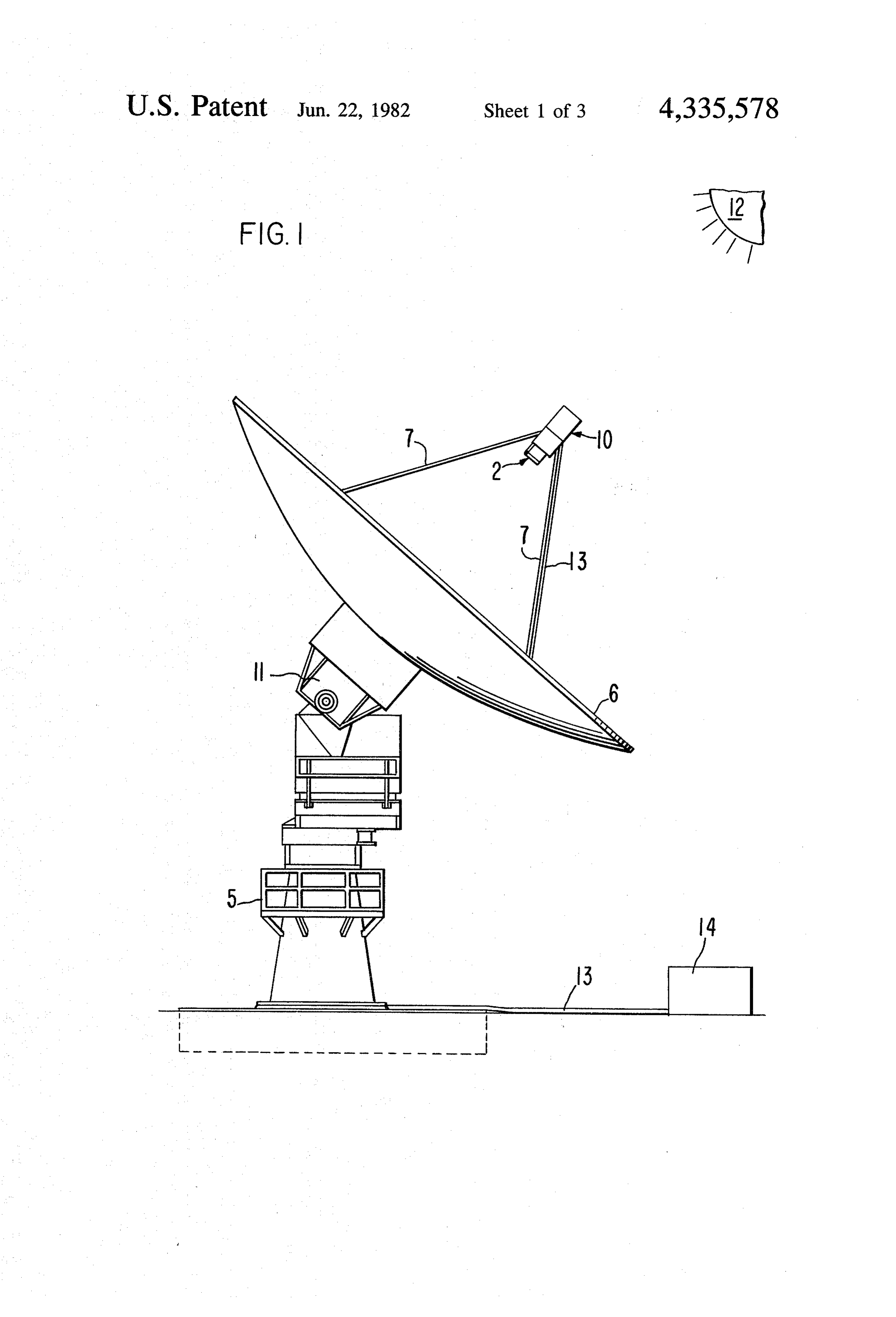
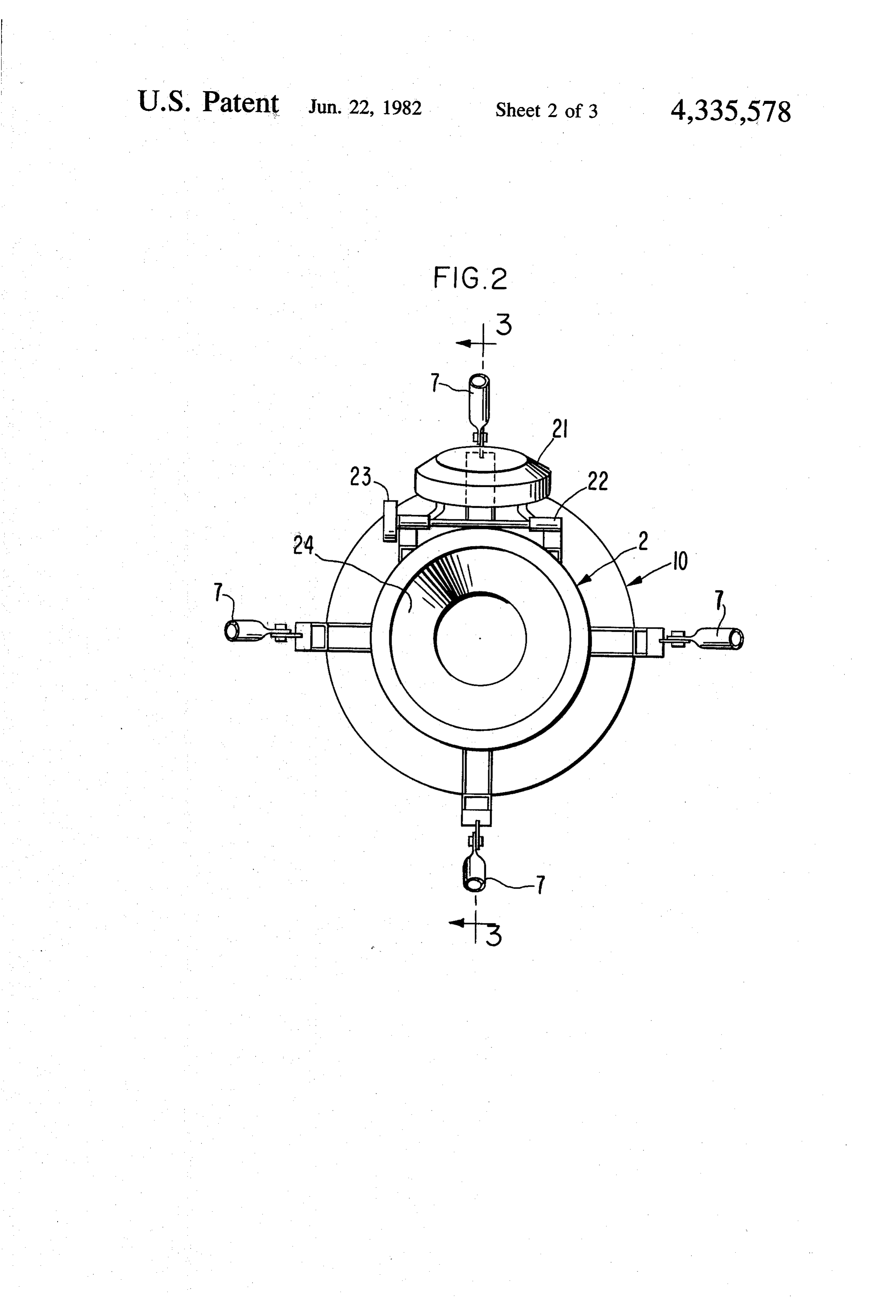
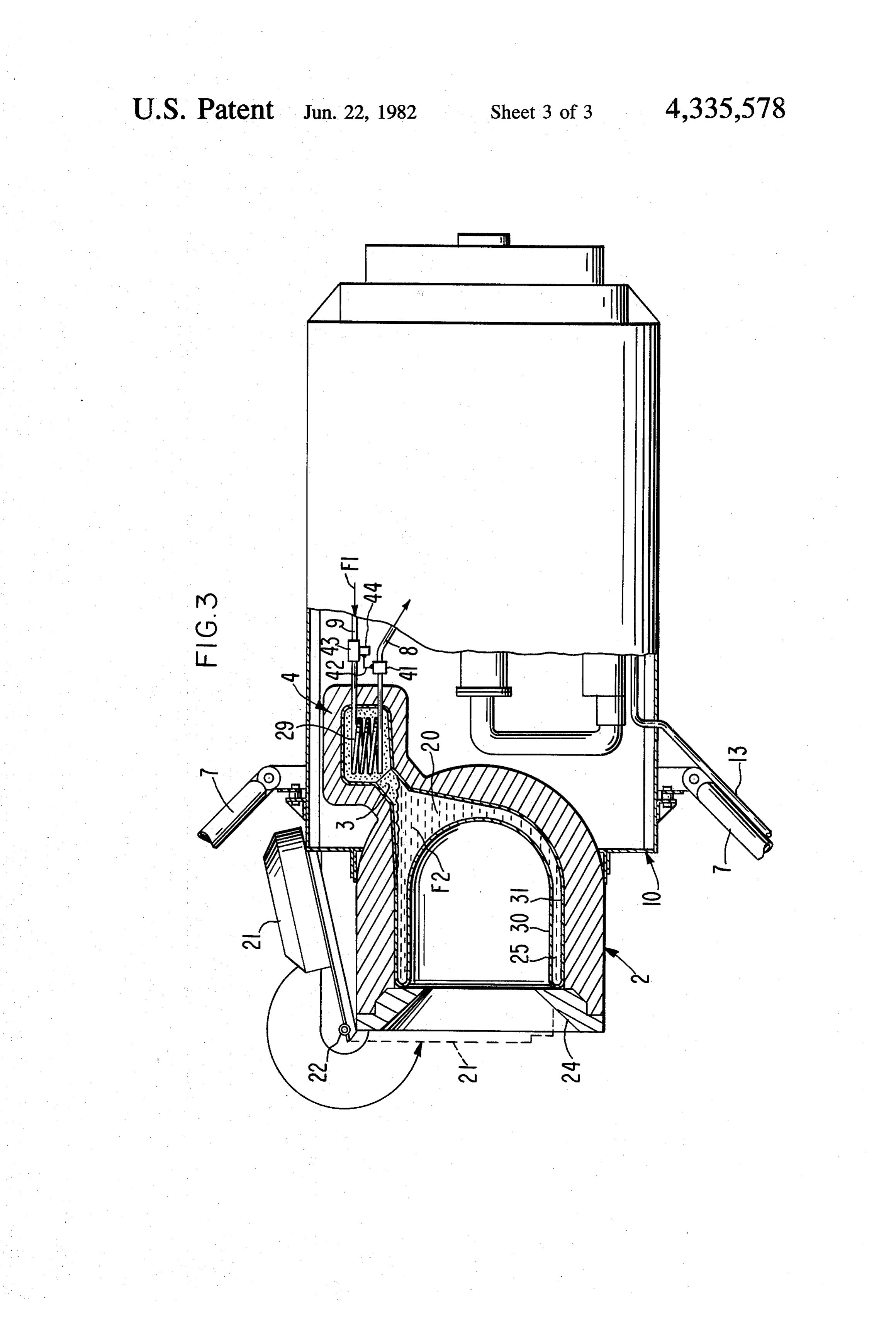
U.S. Pat. No. 3,482,625 is a non-solar system which BRIEF DESCRIPTION OF THE DRAWINGS bubbles Freon (TM) into water. It discloses a heat ex changer having cooling coils surrounded by a liquid These and other more detailed and specific objects through which a gas is bubbled. and features of the present invention are more fully U.S. Pat. Nos. 4,111,184 and 3,998,206 show solar 45 disclosed in the following specification, reference being receivers not having heat exchangers; U.S. Pat. No. had to the accompanying drawings, in which: 4,135,367 is a heat pipe having a wick; U.S. Pat. Nos. FIG. 1 is a schematic illustration of the invention in a 3,563,305 and 1,922,509 are secondary references. typical environment at the focal point of a parabolic dish concentrator;
SUMMARY OF THE INVENTION 50 FIG. 2 is an end view of the present invention viewed The present invention is a novel solar power con from the solar receiver end; and verter comprised of a solar receiver coupled to a heat FIG. 3 is a cross-sectional side view of the present exchanger. The receiver is a double-walled vessel invention taken along the view 3-3 of FIG. 2. shaped in the form of a cylindrical cavity which is de DESCRIPTION OF THE PREFERRED signed for efficient entrapment of concentrated solar 55 EMBODIMENTS energy. The deposited solar energy is distributed along the inner (cavity) surface of the receiver and heat is FIG. 1 shows the invention in a typical environment transferred through the wall to a (secondary) fluid kept at the focal point of a parabolic dish concentrator 6 in a boiling liquid pool within the sealed annular spaces having a reflective surface which focuses the radiation of the vessel. from the sun 12 into the solar receiver 2. Alternatively, The secondary fluid is vaporized at a rate which is other means to concentrate the sun's rays such as a proportional to the net entrapped solar flux and com Fresnel lens or reflector can be employed in lieu of dish mensurate with the thermophysical properties of this 6. The parabolic dish concentrator 6 is mounted above fluid, e.g., vapor pressure, temperature and latent heat the ground by suitable support means such as steel and of vaporization. The secondary fluid vapor rises by free 65 concrete base 5. A pivoting mechanism 11 allows the convection forces through a pipe to a heat exchanger dish to move freely through, preferably, 360 of azi which is mounted above the level of the boiling liquid muth and 90' of elevation. Solar receiver 2 is con pool in the receiver. The vapor condenses on the sur strained to move with dish 6 by appropriate mounting 6 means such as rigid support bracket 7 which provides ing energy loss. A motor 23 is mounted at one end of for a fixed relationship between receiver 2 and dish 6 pivot 22 to provide power to swing the door open or while blocking only a small portion of the radiation shut as necessary. Motor 23 can be actuated by light from sun 12. sensing means such as a photo-conductor which pro In FIG. 3, it can be more clearly seen that solar re- 5 vides an electrical current that automatically activates ceiver 2 is connected via vapor pipe 3 to heat exchanger the motor to open or shut door 21 based upon a certain 4 which is in turn connected via inlet pipe 9 and outlet predetermined threshold of light radiation emanating pipe 8 to heat extracting means 10 which may be, for from sun 12.
example, a heat engine having a generator, which con One purpose of door 21 and the major purpose of lips verts the heat energy to rotational mechanical energy 10 24 of receiver 2 is to protect receiver 2 and associated and thence to electricity. The electricity is drawn from apparatus from impingement of solar radiation when engine 10 by conventional means such as cable 13 for the concentrated solar beam is not centered on the aper distribution to power grid 14. (See FIG. 1). ture of receiver 2. Consequently, door 21 and lips 24 are Vapor pipe 3 is situated at the upper portion of the fabricated of extremely high heat resistant materials closed end (i.e., the end not facing concentrator 6) of 15 such as ceramics, e.g., silicon carbide, silicon nitride, or receiver 2 and is normally connected at an angle with boron nitride; or carbon or graphite composite materi respect to the horizontal axis of receiver 2 so as to pro als. The outer surfaces of receiver 2, vapor pipe 3, and vide an unobstructed path for vapor which accumulates heat exchanger 4 other than lips 24 and door 21 are in dome section 20 of receiver core 25 to rise through covered with effective heat insulation materials such as vapor pipe 3 to heat exchanger 4, and to provide an 20 alumina-silica blankets or graphite composite. unobstructed path to permit gravity-assisted return of Inner wall 30 and outer wall 31 of core 25 are fabri secondary fluid condensate back to receiver 2, regard cated of a material which is strong, thin, is a good heat less of the orientation of receiver 2 with respect to the conductor and is able to withstand high temperatures. earth's horizon. Dome section 20 is an enlarged region In addition, if the fluid employed for the secondary fluid of core 25 located at the upper nonconcentrator end of 25 (the fluid within core 25) is corrosive, then the material receiver 2 and provides a large liquid-to-vapor interface for walls 30 and 31 must be able to withstand corrosion; area which reduces fluid flow velocity at this interface. in such a case, stainless steel is a good selection. Other Core 25 of receiver 2 is a sealed container formed of choices include steel, E-Brite (TM), and Alonized (TM) two concentric cylinders joined at the aperture end of steel. This same material selected for walls 30 and 31 receiver 2 (i.e., the end facing parabolic dish 6) in a half 30 can be used for all the supporting structure of receiver toroid and at vapor pipe 3 end in the form of two half 2, vapor pipe 3, and heat exchanger 4. spheres cut by the dome-shaped section 20 by means of Interior wall 30 can be wicked along its entire interior which vapor pipe 3 joins core 25. A hollow annular surface (i.e., the surface within core region 25) to facili core region 25 is thus formed between the two ends of tate the wetting of the surface as necessary to prevent receiver 2. Core 25, the interior of vapor dome section 35 localized burn-out which can occur if the local fluid 20, vapor pipe 3, and heat exchanger 4 constitute a heat transfer rate is substantially less than the local solar sealed containment vessel for the secondary fluid. Lips flux. In this circumstance, the wall temperature can rise 24 are located circumferentially around the aperture of to the melt point, with subsequent destruction of the receiver 2 as shown in the drawings. surface.
The horizontal position of receiver 2 shown in FIG. 40 Within core 25 is the secondary fluid (F2) in liquid 3 corresponds to a position wherein dish 6 is tracking form; in vapor dome section 20, the liquid partially sun 12 at the horizon, i.e., zero degree elevation. As dish changes into a vapor, i.e., gaseous, state by virtue of the 6 rotates through its full 90 elevation arc as it tracks sun intense heat conducted into core 25 through wall 30 as 12 to a full overhead position in the sky, vapor pipe 3 a result of the concentrated solar radiation which enters always remains situated above receiver core 25 and heat 45 through the aperture of receiver 2. The heat then trav exchanger 4 always remains situated above vapor pipe els with the rising vapor upwards through vapor pipe 3 3. The preferred angle between vapor pipe 3 and the into heat exchanger 4.
earth's horizon is between 10 and 90 inclusively. Thus, The interior surface of pipe 3 may be wicked to facili for the case where dish 6 is capable of a full 90 of tate the return of F2 condensate back to core 25 particu elevation tracking, pipe 3 should make an angle of be- 50 larly at low gravity gradients (low angles of the vapor tween 10 and 80” inclusively with respect to the hori pipe with respect to the horizon) and/or at low F2 Zontal axis of receiver 2. Assuming this latter angle is vapor pressure. An optional valve (not illustrated) may 10, when dish 6 is in a full upright position (elevation be installed within vapor pipe 3 to stop the flow of angle equals 90), vapor pipe 3 then makes an angle of vapor to heat exchanger 4, and thus stop the flow of 80' with respect to the horizon. When dish 6 is in a 55 heat to heat extractor 10 under certain conditions, e.g., horizontal position (elevation angle zero degrees), when a preestablished maximum or minimum tempera vapor pipe 3 then makes an angle of 10° with respect to ture of fluid F2 has been reached. A switch which the horizon. If dish 6 is not capable of tracking the closes the valve can signal this information via a ther lower 10 of elevation, then pipe 3 can make an angle of mocouple. Heat extractor 10 can be shut down upon the between 0 and 80 inclusively with respect to the hori- 60 occurrence of these same conditions. zontal axis of receiver 2. Within heat exchanger 4, vapor F2 encounters the Cavity door 21 is a movable door; when in its position cooler primary fluid (F1) flowing within heat exchange covering the aperture to receiver 2, it prevents the heat element 29, which is an element such as a coil having a within receiver 2 from escaping, thereby reducing en high surface area per unit volume and whose function is ergy losses during cloudy days and at night. Door 21 is 65 to provide the heat exchange. Along the outer surface perferably pivotally mounted about pivot 22 (see FIG. of element 29, vapor F2 condenses; the condensate 2). When door 21 is swung open as shown in the draw flows downward by force of gravity back through ings, it presents a low profile to the sun's rays, minimiz vapor pipe 3 into vapor dome 20 and into core 25.
Page 7scan →
Vapor F2 gives up heat to fluid F1 according to F2's ...(5) it should exhibit stable pool boiling over a wide latent heat of vaporization. Fluid F1 is pumped or oth range of operating conditions; erwise flows through the system comprising element 29, (6) it should be non-corrosive, non-toxic, non-flamm outlet pipe 8, into heat extractor 10, and back through able, and chemically stable; inlet pipe 9 into element 29. - (7) it should be easy to handle and to fill and drain the It is desirable to remove heat from heat exchanger 4 receiver;
at the same rate that heat enters receiver 2 to maintain (8) its freeze point should be below the ambient sys system temperature, to heighten efficiency, and for tem, conditions;
reasons of safety. This can be accomplished by ensuring (9) it should have a high heat capacity per unit vol that the temperature of F1 stays at a substantially cons 10 ume; and stant level corresponding to the preselected optimum (10) it should be inexpensive. operating temperature of the system. FIG. 3 illustrates Acceptable choices for the secondary fluid are: For how this can be accomplished. Temperature sensing medium temperature applications (up to 427 C): means 41, which can be a thermocouple, is placed (1) Terphenyls, including the meta-, para-, and ortho within outlet pipe 8 at a point between heat exchanger 15 terphenyls or mixtures thereof; these have the ad 4 and heat extractor 10. Thermocouple 41 produces on vantage of being noncorrosive; however, they start wire 42 an electrical voltage proportional to the amount to degrade substantially at temperatures above by which the temperature of F1 exceeds the set point of approximately 427 C. (800 F). The vapor pres thermocouple 41, which has been preset to the desired 20 same sure of terphenyl is about two atmospheres at the operating temperature of the system. Wire 42 is con operating temperatures. nected to variable speed motor 44 which in turn drives (2) Sulfur, which may be used for higher tempera variable speed pump 43 inserted in inlet pipe 9 between tures. A major problem with sulfur is that it is heat exchanger 4 and heat extractor 10. An increasing corrosive. Its vapor pressure is approximately one voltage on wire 42 causes motor 44 to speed up which atmosphere at 427 C. (800 F). causes F1 to flow faster, thereby lowering the tempera 25 . (3) Sulfur with additives such as iodine or bromine ture of F1. The system thereby self-corrects to the de which change the molecular structure to keep the sired operating temperature. Alternative to the use of a viscosity of the fluid low. variable speed pump, pump. 43 can be a fixed speed (4) Aluminum bromide or other salts. pump, in which case a flow control valve (not illus 30 matelyFor high temperature applications (above approxi trated) is inserted in inlet pipe 9 between heat exchanger 600° C):
4 and pump 43. In this case, wire 42 is connected to the (1) Liquid metals, e.g., sodium and potassium, which valve, which admits a greater F1 flow as the voltage on have a vapor pressure of approximately one-half wire 42 increases, thus cooling F1. atmosphere at 816' C.
Heat extractor 10 is any device which processes the 35 (2)If
Salts.
the secondary fluid is sulfur, the material for core heated fluid, such as a heat engine, e.g., Rankine, Stir walls 30 and 31 may be aluminized steel, which is less ling or Brayton cycle engine, which generates rota expensive tional mechanical energy from the heat applied to the terphenyl, than stainless steel. If the secondary fluid is engine via outlet pipe. 8. The mechanical energy can nary steel. walls 30 and 31 may be fabricated of ordi then be converted into electrical energy e.g., by means of a generator as is conventionally known. Alterna EXAMPLE 1. tively, heat extractor 10 may be an industrial process Heat extractor 10 is a Rankine engine; F1 is toluene.
This
The primary fluid is selected to optimize the perfor with iodineis a medium temperature application. F2 is sulfur or bromine added. Core walls 30 and 31 as mance of extractor 10. For a Rankine cycle engine, fluid 45 well as other structural components of receiver 2, vapor F1 is typically toluene, with an upper temperature limit pipe 3, and heat exchanger 4 are fabricated of Alonized of approximately 427 C. (800 F). For a Brayton cycle (TM) steel. Door 21 and lips 24 are fabricated of silicon engine, fluid F1 is a gas such as air with a maximum carbide.
temperature of 816°C. (1500 F) for a metal engine and vapor pipeThe 3, remaining outer surfaces of receiver 2, and heat exchanger 4 are insulated with an about 1371 C. (2500 F) for a ceramic engine. For a 50 alumina-silica blanket.
Stirling cycle engine, primary fluid F1 is a gas with a low molecular weight such as hydrogen, or, helium, EXAMPLE 2 operating at temperatures similar to those of the Bray Heat extractor 10 is a Stirling cycle engine employing ton cycle engine. helium as the primary fluid, or a Brayton cycle engine The choice of the secondary fluid is not strongly 55 employing air as the primary fluid. The system operates dependent on the choice of primary fluid. It is of no at 816 C. (high temperature). The secondary fluid is concern whether the primary fluid undergoes a phase change or not, but it is essential to the working of the liquid sodium. Walls 30 and 31 are stainless steel. Door invention that the secondary fluid undergoes a phase receiverlips2, 24 21 and are silicon carbide. Remaining portions of change. The following are the criteria for selecting the 60 less steel coveredpipe vapor 3, and heat exchanger 4 are stain with aluminum-silica insulation.
secondary fluid: The invention has the following distinct advantages (1) it should have low vapor pressure at the system over the conventional direct heating methods: operating conditions; To a large extent each of the fluids F1 and F2 can be (2) its critical point should be above the maximum optimized independently from each other. For example, operating conditions of the primary fluid; 65 it might be necessary that fluid F1 be under high pres (3) it should have high heat transfer capability when sure in order to drive a particular type of engine. boiling; The fact that the secondary fluid changes state from (4) it should have a high burnout heat flux; a liquid to a gas makes for a very efficient system com 8 pared with a single-phase free (or forced) convection changer, and for the liquid form of said secondary fluid type of system in which the secondary fluid remains a to flow from said heat exchanger into said receiver. liquid. Thus, the size, weight and cost of the system can 3. The apparatus of claim 2 wherein said vapor pipe is be minimized because small heat transfer surface areas connected to said solar receiver at an angle with respect are acceptable at both the solar concentrator and heat 5 to the horizontal plane of said receiver, and the horizon exchanger ends of the system. Excessive wall tempera tal plane of the receiver is oriented with respect to the earth's horizon, in such a way that the secondary fluid ture or burnout is virtually eliminated during operating in vapor form is free to rise up through said vapor pipe conditions for both the core walls 30 and 31 and heat into said heat exchanger when said secondary fluid is exchanger 4 walls. heated, and said secondary fluid in liquid form is free to Because of the separation of the fluids, the design of 10 fall by gravity receiver 2 is relatively insensitive to the choice of pri vapor pipe into from said said heat exchanger through said receiver when said secondary fluid mary fluid. The mechanical structure of the system is is cooled.
simple. The system is inherently safe due to the low 4. The apparatus of claim 3 wherein said vapor pipe operating pressures (typically, the fluid pressure of the 15 makes secondary fluid, which is equal to its vapor pressure, is respectantoangle of between 10 and 80', inclusively, with the horizontal plane of said solar receiver.
approximately one atmosphere, but since its contain 5. The apparatus of claim 1 further comprising the ment vessel is sealed, this pressure may vary). The liq additional element of heat extracting means connected uid portion of F2 plus door 21 forms an inherent heat to said second chamber at an inlet and an outlet thereof. buffer which stores heat during periods of inclement 20 6. The apparatus of claim 5 wherein said heat extract weather. ing means is from the class consisting essentially of heat The above description is included to illustrate the engines and process heat applications. operation of the preferred embodiments, and is not 7. The apparatus of claim 6 further comprising the meant to limit the scope of the invention. The scope of additional element of a movable door affixed to said the invention is to be limited only by the following 25 receiver and disposed to move so that it alternatively claims. From the above discussion, many variations will blocks and keeps open the aperture to said receiver, said be apparent to one skilled in the art that would yet be blocking made to occur during periods when solar flux encompassed by the spirit and scope of the invention. is not substantially present. What is claimed is: 8. The apparatus of claim 7 wherein said heat extract 1. An internal cavity solar power converter compris- 30 ing means is a Rankine cycle heat engine; ing: said primary fluid is toluene; a solar receiver formed between two concentric, said secondary fluid is sulphur with iodine or bromine generally cylindrical sleeves, said receiver substan additives;
tially filled with a pool of secondary fluid which 35 said receiver and heat exchanger are fabricated of changes phase from a liquid to a vapor upon the steel;
impingement of solar radiation thereon; said door and the region surrounding the opening of an annular seal connecting said sleeves at a first end said receiver are fabricated of silicon carbide; and thereof; the outer surfaces of said heat exchanger, and the outer surfaces of said receiver other than said door a fixed aperture formed by said annular seal and dis 40 and said region surrounding said opening, are insu posed to permit concentrated solar radiation to lated with an alumina-silica blanket. impinge upon an interior surface of said receiver; 9. The apparatus of claim 7 wherein said heat extract and ing means is a Stirling cycle heat engine and said pri a heat exchanger coupled to an end of said receiver mary fluid is helium;
opposite its apertured end, having a first chamber 45 said secondary fluid is liquid sodium; adapted to receive secondary fluid from said solar said solar receiver and said heat exchanger are fabri receiver, said exchanger further having a second cated of stainless steel;
chamber containing a primary fluid; said door is fabricated of silicon carbide; and wherein said secondary fluid undergoes a phase said solar receiver and heat exchanger are covered change from a vapor to a liquid as it gives up heat 50 with aluminum-silica insulation. to said primary fluid within said heat exchanger. 10. Apparatus of claim 1 further comprising the addi 2. The apparatus of claim 1 further comprising the tional element of temperature regulating means con additional element of a vapor pipe connected to said nected to said heat exchange element for maintaining solar receiver and to said heat exchanger, said pipe the temperature of said primary fluid substantially con providing a path for the vapor form of said secondary 55 Stant, 2k k k ck sk fluid to flow from said receiver into said heat ex
Provenance
- Collection
- Patents citing this work
- Pages
- 8
- Method
- pdftotext (the PDF's own text layer) + pdftoppm 300dpi page scans
- Patent office record
- patents.google.com →
- Source
- Google Patents citing-documents table
- Assignee
- Ford Aerospace & Communications Corporation
- Published
- 1982-06-22
- Transcribed from
- patentimages.storage.googleapis.com →