

patent · US4535754A
Manufactured fuel assisted solar heat exchanger
20 August 1985
Text
Page 1bibliographic recordscan →
United States Patent (19)
Darr
(54) MANUFACTURED FUEL ASSISTED SOLAR
HEAT EXCHANGER
(75) Inventor: Harry W. Darr, Kirkland, Wash.
Assignee: D&M Investments, Yakima, Wash.
Related U.S. Application Data (63) Continuation-in-part of Ser. No. 236,691, Feb. 23, 1981, abandoned.
(51 Int. Cl.................................................. F24J 3/02 52 U.S. Cl. .................................... 126/419; 126/427;
2,213,894 9/1940 Barry ................................... 26/419
3,998,205 12/1976 Scragg et al. ................ - - - - - - - 126/427 4,007,776 2/1977 Alkasab ............................... 126/437 4,086,911 5/1978 Futch .................................. 126/443 4,100,756 7/1978 Albertson ........................... 62/235.1 4,222,244 9/1980 Meckler ............................. 62/235.1 4,256,090 3/1981 Imperiale ............................ 126/427
4,350,144 9/1982 Beckwith ............................ 126/427
Primary Examiner-Carroll B. Dority, Jr.
Attorney, Agent, or Firm-Dowrey & Cross
A heat exchange system operates on solar energy, sup plemented by nonsolar manufactured fuels such as elec tricity, natural gas, propane and the like. The system includes a solar heat collector and a heat exchanger for delivering the collected solar heat to a water heater and furnace. Supplemental heating means utilizing a nonso lar fuel will heat the collector if an insufficient amount of solar heat is available. The system can also include an air conditioning system.
8 Claims, 14 Drawing Figures
Drawings
Page 2drawing sheetscan →
Page 3drawing sheetscan →
Page 4drawing sheetscan →
Page 5drawing sheetscan →
Page 6drawing sheetscan →
Page 7drawing sheetscan →
Page 8scan →
fits within a generally cylindrical closed transparent
MANUFACTURED FUEL ASSISTED SOLAR HEAT housing to prevent escape of heat to the environment. EXCHANGER The invention is easily installed and fully compatible with preexisting domestic heating systems. The inven
BACKGROUND OF THE INVENTION 5 tion replaces the heat-producing elements of space and This application is a continuation-in-part of aban water heater systems, and utilizes existing furnaces, doned application Ser. No. 236,691, filed Feb. 23, 1981. fans, ductwork, hot water tanks and the like, with little This invention relates to the field of heat exchange modification of the same.
devices for water or space heating, and more particu 10 The solar heat collecting apparatus of the preferred larly to the field of solar energy heat exchange devices. embodiment can be mounted on the ground or atop a With rising fuel costs, achieving efficiency in water pole or structure or in any other convenient position and space heating by the utilization of freely available where it will be subject to insolation. The appearance of energy such as that contained in solar radiation is cru a home or other building need not be changed to ac cial in both domestic and commercial settings. Unfortu 15 commodate the device.
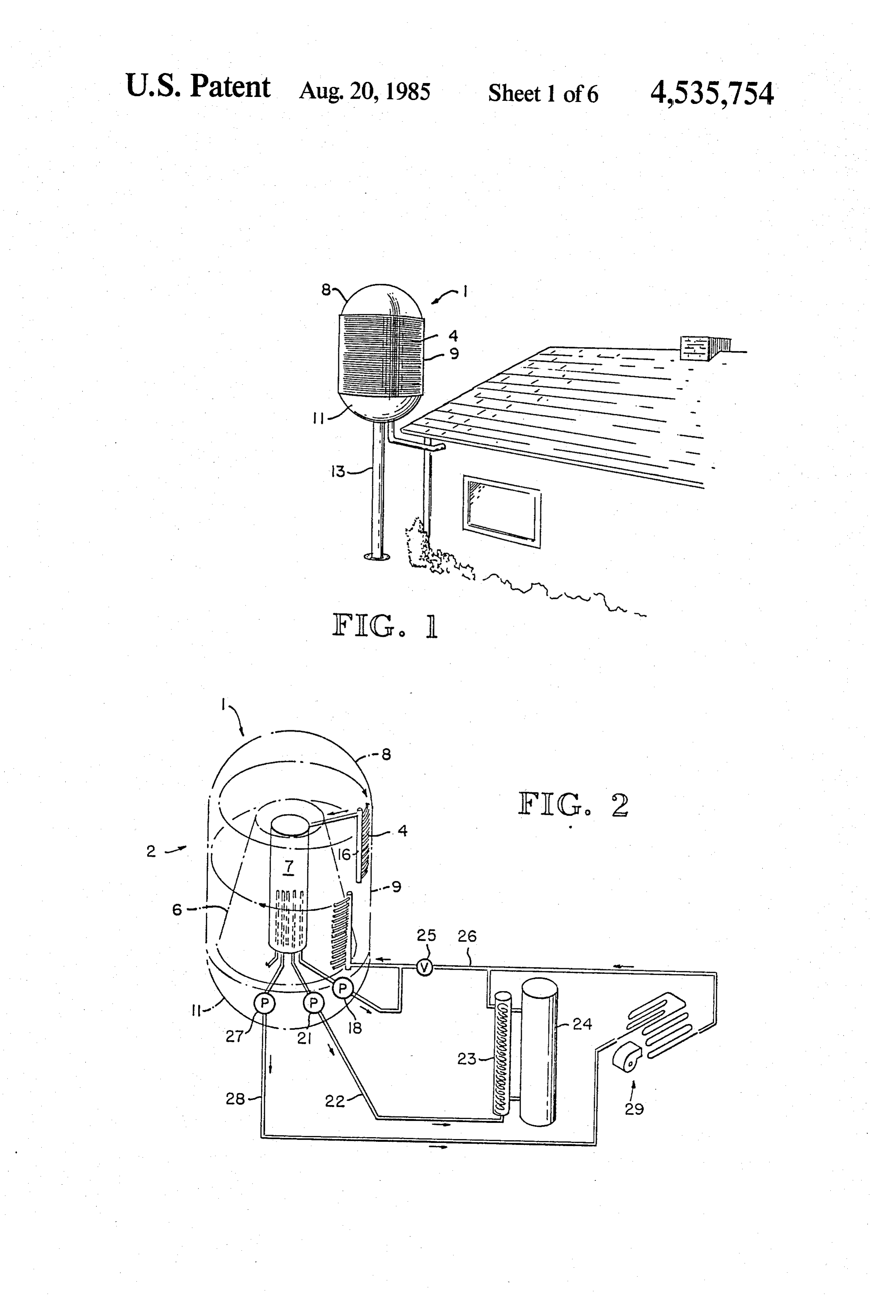
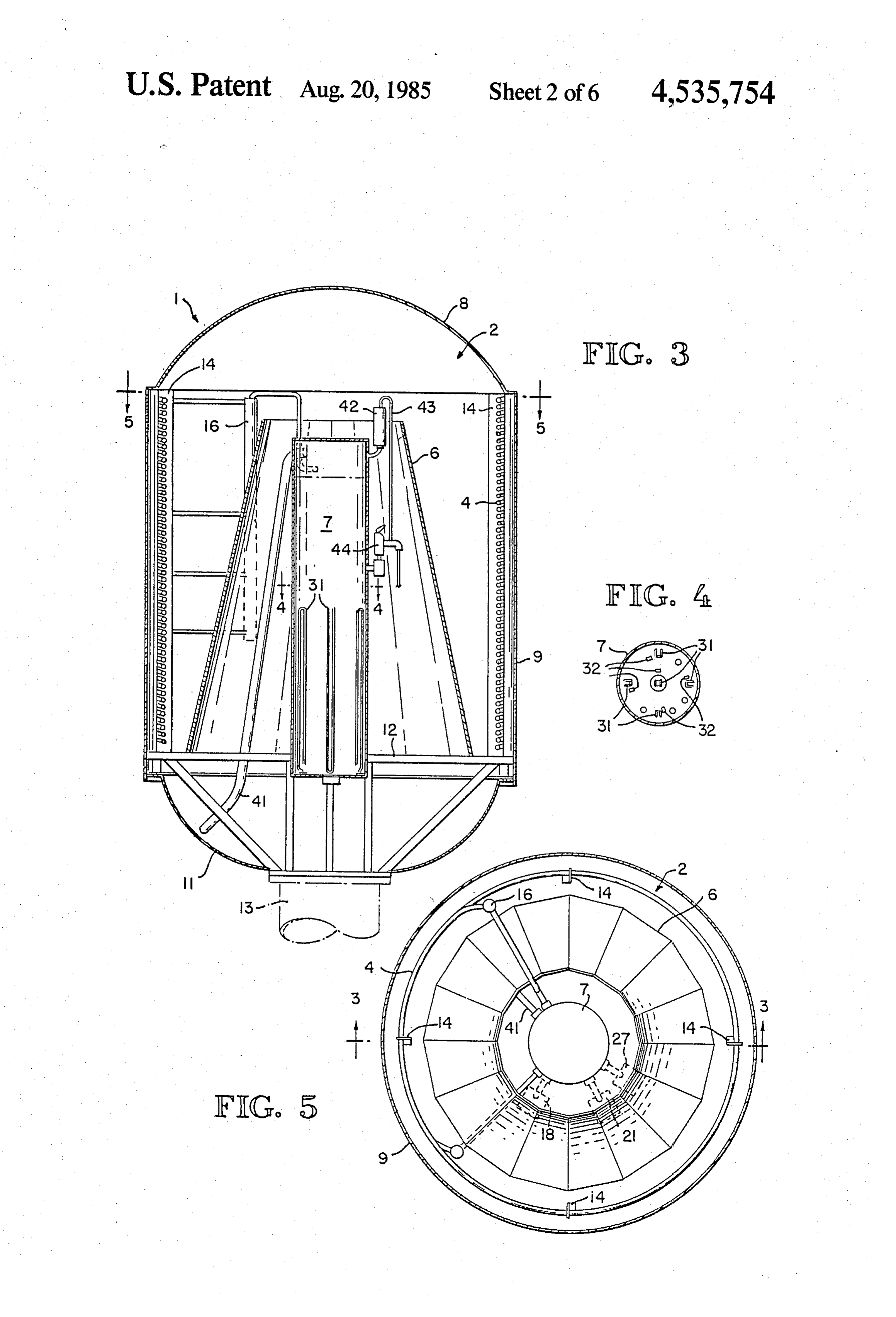
nately, prior art solar heating devices have serious BRIEF DESCRIPTION OF THE DRAWINGS shortcomings which have prevented the commercial FIG. 1 is a perspective view of the invention installed success and widespread use of these devices. Many for domestic water and space heating. prior art devices are not cost-effective, or do not result in sufficient monetary savings to justify the investment 20 FIG. 2 is a schematic diagram of the invention, show and effort involved in their installation. Some require ingFIG. its connection with a water heater and furnace. 3 is a cross-section of the heat collection zone of expensive adaptations to existing structures and heating an embodiment of the invention using an electrical sup systems. Most are of no use when the sun does not shine, and hence are impractical in areas frequently subject to plemental heat source, taken along line 3-3 of FIG. 5. FIG. 4 is a cross-section of the tank of the embodi overcast and cloudy weather. Some solar energy heat 25 ment of FIG. 3, taken along line 4-4 of FIG. 3. exchange systems are inherently limited in their heat FIG. 5 is a cross-section of the heat collection zone of supplying capacities and thus are not useful in heating the invention, taken along line 5-5 of FIG. 3. large homes. And many take up considerable amounts FIG. 6 is a diagram of the electrical system of the of space, making them unsuitable for use in small homes. embodiment of FIG. 3.
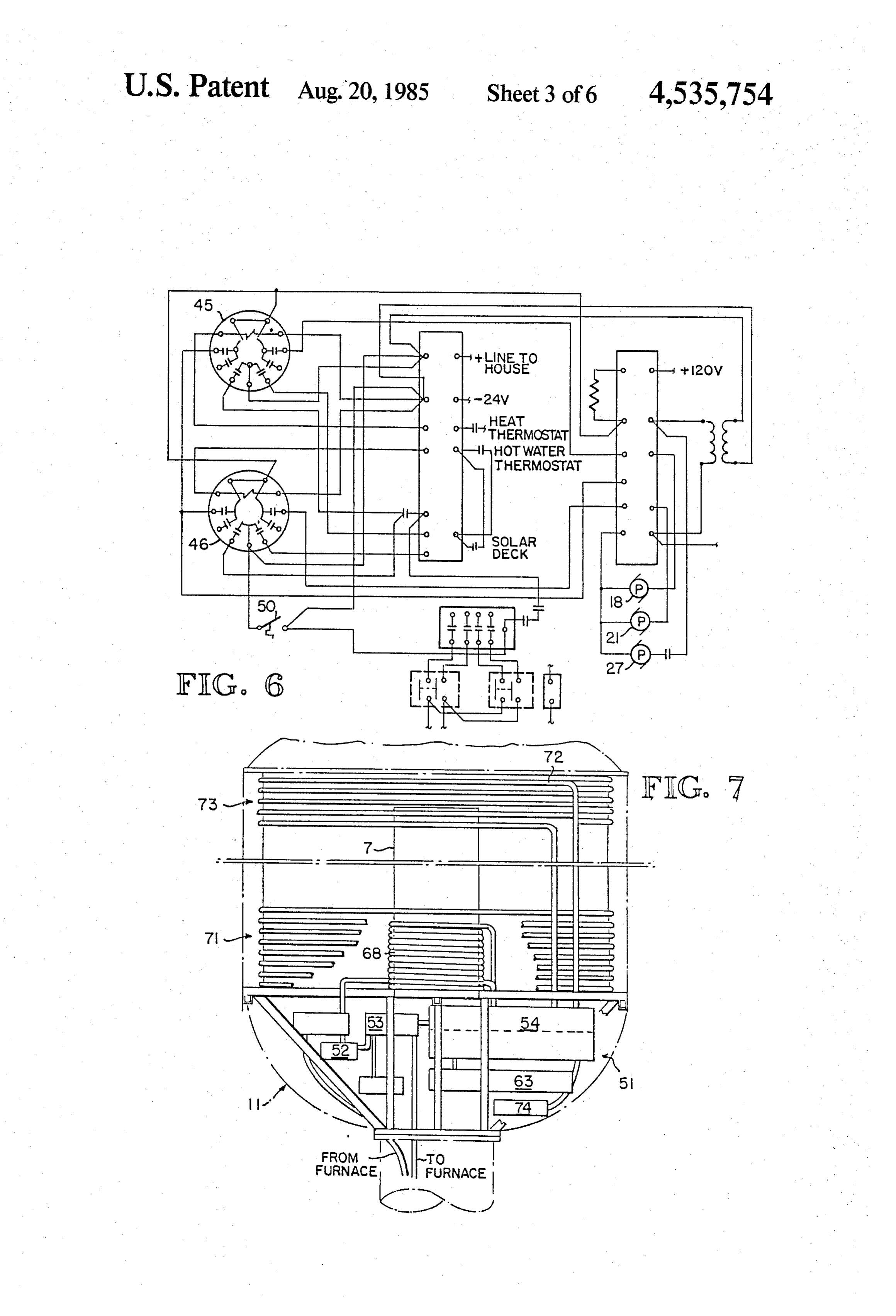
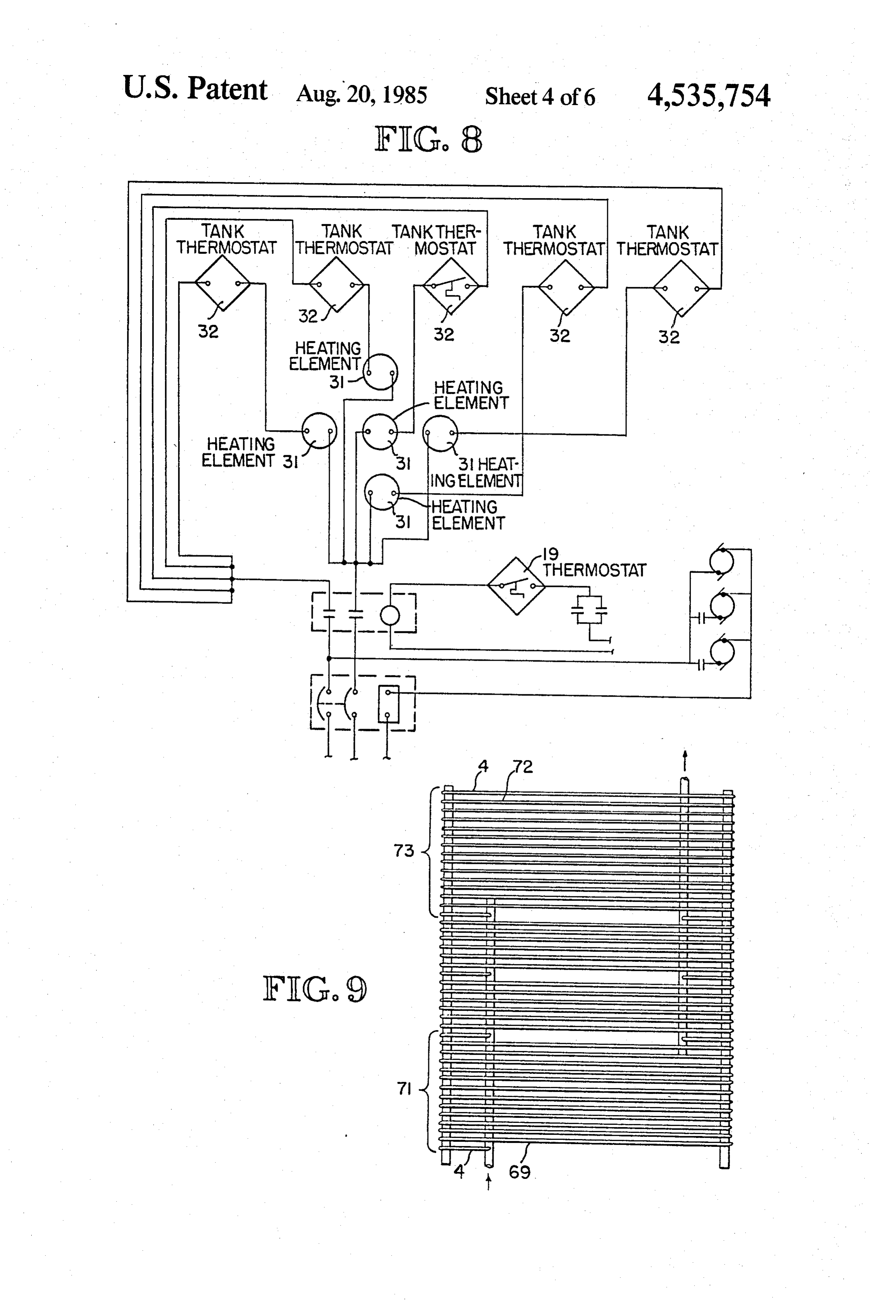
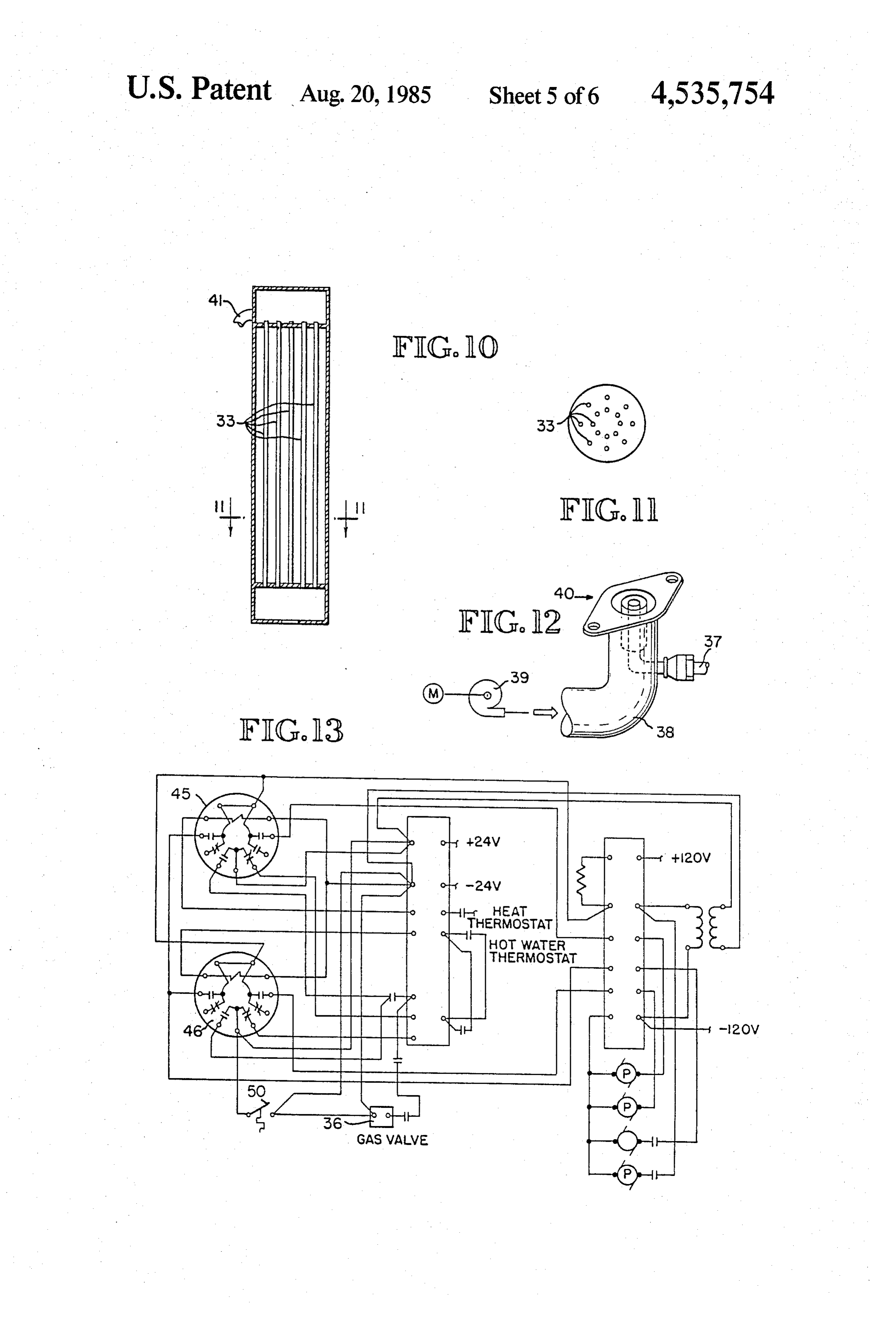
An ideal solar heating system would utilize non 30 FIG. 7 is a schematic diagram of an embodiment of manufactured and freely available energy sources such as solar energy, and would do so efficiently and cost theFIG. invention adapted for air conditioning purposes. 8 is a schematic diagram of the temperature effectively. An ideal system would be compact and sensing and electrical control system for the supplemen easily installed, with little modification of preexisting tal heating system structures being necessary. This system would be com 35 FIG. 9 is a detailofofthe FIG. 3 embodiment. patible with existing space and water heating equip embodiment of FIG. 7. heat collection tubing of the the ment, and would be adaptable for other uses, such as air FIG. 10 is a sectional view of an embodiment of the conditioning, pool and hot tub heating, etc. It would invention using a natural gas or propane supplemental also include a means of operation when solar energy is fuel source.
unavailable. FIG. 11 is a cross-section of the tank of the embodi SUMMARY OF THE INVENTION ment of FIG. 10 taken along line 11-11 of FIG. 11. The present invention is a heat exchange system FIG. 12 is a detail of the gas jet of the gas fueled embodiment of FIG. 10.
which operates on solar energy, supplemented by non FIG. 13 is a diagram of the electrical system of the solar manufactured fuels such as electricity, natural gas, 45 embodiment of FIG. 10.
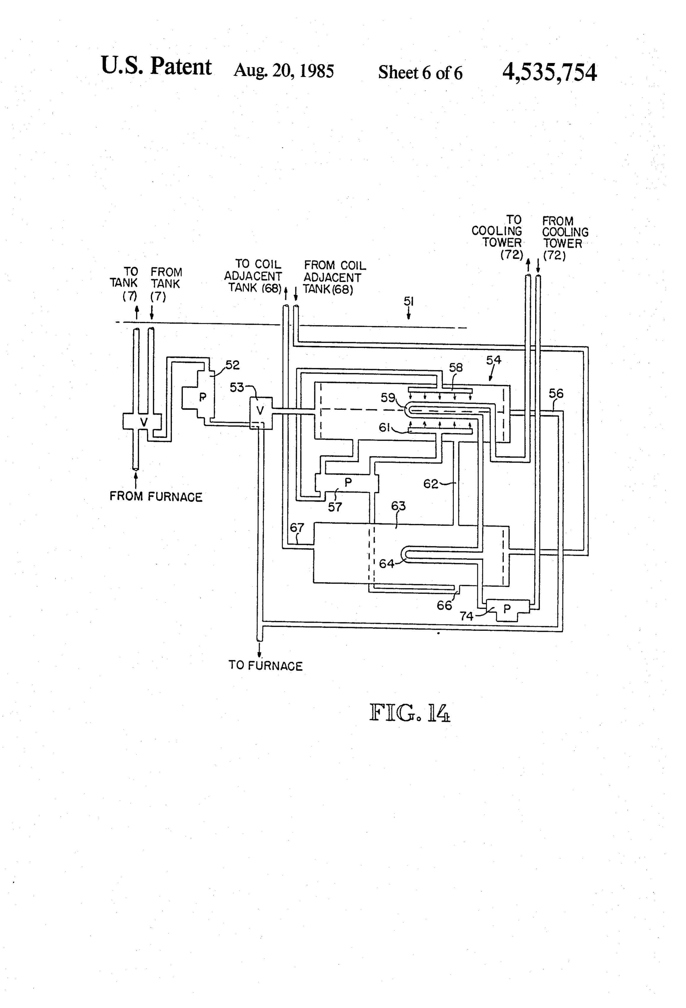
propane and the like. The system includes a solar heat FIG. 14 is a schematic flow diagram of the refrigera collector and a heat exchanger for delivering the col tion system of the FIG. 7 embodiment. lected solar heat to water for domestic use or air to be conducted through a forced air heating system, or other DETAILED DESCRIPTION OF THE heat receiving means. Supplemental heating means uti 50 DRAWINGS lizing a nonsolar fuel will, when necessary, heat the Referring first to FIGS. 1-5, a preferred embodiment collector in response to means such as a temperature of the solar heat exchanger 1 of the present invention sensor which detects if an insufficient amount of solar includes a heat collection zone 2 in which heat from the heat has been collected. The system also includes a sun and, under certain below-described circumstances, control for regulating delivery of heat by the heat ex 55 from supplemental heat sources, is accumulated in a changer. fluid contained within a helical arrangement of copper The present invention is highly efficient, with the tubing, or other heat conductive tubing, forming cylin preferred embodiment taking the fullest possible advan drical coils 4 which, in normal use, will be positioned on tage of all available energy sources. In the present in a vertical axis. Positioned within the coils 4 of the pre vention, solar heat is absorbed by a fluid held in coiled 60 ferred embodiment is a reflector 6 which can be con tubing of heat conductive material. A solar reflector structed of any suitably reflective material, such as positioned within the coils provides maximum reflec stainless steel or that sold under the trademark MY tion of sunlight onto the coils. The reflector is formed in LAR. The reflector 6 preferably is formed of a series of a generally frusto-conical shape, having a large number approximately 32 concave facets arranged in a gener of concave facets to provide the fullest possible reflec 65 ally frusto-conical configuration coaxial with the coils 4 tion of sunlight onto the coils. Furthermore, because the and having its wider end as its base. While flat facets or reflector is disposed within the coils, maximum insola a cylindrical frusto-conical shape can, of course, be tion of the coils is achieved in a compact design, which utilized in the invention, it is preferable to form the 9 reflector 6 from one or more flat sheets of reflective water in the preexisting hot water system. The water is material which are overbent to form slightly concave heated by fluid in the heat exchanger 23 while the hot surfaces, allowing the reflector 6 to approximate para water tank 24 acts as a storage tank. After circulating bolic reflection. This results in maximum reflection of through the heat exchanger 23, the fluid flows through solar energy from the reflector 6 onto the coils 4. 5 return line 26 and valve 25 therein back to the lower Positioned within the reflector 6 is a cylindrical tank manifold 17 in the heat collection zone 2 to be recircu 7, coaxial with the coils 4 and reflector 6. As will be lated and reheated.
explained more fully below, the tank 7 receives fluid A second pump 27 circulates heated fluid from the from the coils 4, and functions both as a reservoir to tank 7 through a second outlet line 28 in parallel with hold this fluid, and also as a boiler in which the fluid can 10 the first outlet line 22, to a conventional and preexisting be heated by nonsolar means. The coils 4, reflector 6 space heating system 29. The present invention is adapt and tank 7 are enclosed in a transparent housing formed able for use with both forced air and hot water heating by an upper dome 8, a cylinder 9, and a lower dome 11 systems. In a forced air system, a heat exchanger trans of a plastic or other suitable material. Single-walled fers heat from the fluid to air which is forced through a construction - of the housing is preferred for greater 15 plenum by conventional fan means such as that already - - - economy, although double-walled construction can be in the heating system. In a hot water system, the boiler used, if desired, for purposes of greater heat insulation. is bypassed, and the fluid is used in place of water to The done 8 and cylinder 9 can be half-silvered on their flow through the piping of the heating system. In either interior surfaces to provide greater reflection of sun case, the existing thermostat will remain as a control for light onto the coils 4. A plate 12 supports the coils 4, 20 the heating system. After circulating through the heat reflector 6, tank 7 and related elements within the hous ing system or heat exchanger, the fluid flows back to the 1Ilg. heat collection zone 2 through return line 26 and valve The entire heat collection zone 2 can be mounted 25. It will be understood, of course, that the present above ground on a pole 13, as shown in FIG. 1, or in invention can be adapted for use with other types of any other convenient position where sunlight is avail- 25 space heating systems or to fit special structural require able, as, for example, on the ground, the roof of a struc ments, in manners which will be obvious to those skilled ture, etc. This is highly advantageous for the home in the art.
owner who may choose the position of the device in The solar heat exchanger of the present invention accordance with aesthetic concerns. Also, the option ofincludes nonsolar supplemental heating means which pole mounting allows the device to be used in areas 30 enables the invention to perform even during overcast where shade from other structures or trees or the like weather when insolation of the coils is insufficient to would not allow the use of roof-mounted or other con heat the fluid therein to the desired degree. In a pre ventional solar heat collector designs. The device is ferred embodiment, these supplemental heating means compact, the heat collection zone 2 standing approxi will utilize either electricity, natural gas or propane as mately five feet tall, and three feet in diameter. 35 an energy source, although any desired supplemental Returning to the preferred embodiment of the heat energy source can be used, with suitable modifications collection zone 2 in greater detail, for greatest effi to the system. Referring first to the preferred electrical ciency, the copper tubing preferably forms four sepa embodiment shown in FIGS. 3 and 4, four supplemental rate, vertically adjacent and interwound coils 4 which heat sources such as electrical resistance heating ele are supported on four standards 14 equally spaced 40 ments 31 are arranged around the periphery of the tank around the circumference of the coils 4. The coils 4 can 7, with a fifth heating element 31 at the center of the have their turns individually wired to the standards 14, tank. Referring to FIG. 8, each of the five resistance or, alternatively, the standards 14 can be formed with heating elements 31 in a preferred electrical embodi projections to hold the turns of the coils 4. Each of the ment is individually controlled by a separate thernostat four coils 4 is coupled to an upper manifold 16 which is 45 32 within the tank 7, which will sense the temperature in fluid communication with the upper portion of the of the fluid in the tank 7 and switch on its associated tank 7, and a lower manifold 17 in fluid communication heating element 31 when fluid temperature drops to a with the lower portion of the tank 7. A pump 18 of a preset limit. Preferably, the preset limits are 165 F., common and commercially available design is mounted 155 F., 145 F., 140 F., and 130 F. Thus, when fluid in the lower dome 11 under plate 12 and circulates heat 50 temperature drops below 165 F., a first heating element absorbing fluid from the bottom of tank 7 through the 31 is switched on; when temperature drops to 155 F., a lower manifold 17, around the coils 4 to the upper mani second heating element 31 is switched on, in addition to fold 16, and into the top of the tank 7. While the fluid is the first, etc. This stepwise activation of the heating circulated through the coils 4 in this manner, it absorbs elements 31 allows efficient use of minimal amounts of heat from impinging solar radiation passing through the 55 electricity for continuous operation of the device dome 8 and cylinder 9, and reflecting off the reflector 6 through periods of unfavorable weather. and interior surfaces of the dome 8 and cylinder 9. As an alternative to electrical heat, other manufac The pump 18 is controlled by a thermostat 19, shown tured fuel sources such as natural gas or propane can be in FIG. 8, which detects the temperature of fluid leav used in the invention to supplement the solar heating of ing the bottom of the tank 7, and switches off the pump 60 the fluid. Preferred embodiments utilizing such alterna 18 if fluid temperature is not at least 145 F., causing the tive fuel sources will be identical to the above-described fluid to remain stationary in the coils 4 and tank 7 until embodiment, except for the supplemental heating sys a greater amount of heat is absorbed. tem. Referring to FIGS. 10-13, in a preferred embodi Referring now to FIG. 2, a conventional pump 21 ment using a gas as supplemental fuel, the fuel will be circulates the heat-containing fluid from an outlet line 65 burned through sixteen boiler tubes 33 arranged in con 22 leading from the bottom of the tank 7 to a heat ex centric circles within the tank 7. A preset thermostat changer 23 cooperating with a conventional hot water connected to a modulating gas valve 36 controls the tank 24, in which heat is transferred from the fluid to amount of gas delivered from a conventional pressur 10 ized gas source to a gas jet 40 at the base of each boiler rounding the reflector 6 and preferably having its seven tube 33 through an inlet line 37 coupled to a conduit 38, turns immediately adjacent and alternating with the with air being supplied by conventional means such as a lowest seven turns of the heat collecting coil 4, forming fan 39. a first coil section 71. The vapor will condense within Referring to FIG. 3, in a system using either an elec these coils and release heat to the tank 7 and coil 4, tric, gas, or other supplemental heat source, a pressure adding to the efficiency of the solar heat exchanger 1. release mechanism including an exhaust outlet 41, air Then, the refrigerant will flow back into the generator check valve 42, bleeder line 43, and pop-off valve 44 is 63.
provided on the tank 7 to ensure safe operation of the The pair of tube bundles 59 and 64 which are shown device. 10 in FIG. 14 form part of a closed circulating system, Referring to FIGS. 6 and 13, in the electrical control which includes a cooling tower coil 72 which, as shown systems for preferred embodiments using either gas or in FIG. 9, preferably has its seven turns adjacent and electric supplemental heat sources, relays 45 and 46 alternating with the uppermost turns of the heat collect control pumps 21 and 27 circulating fluid to the hot ing coils 4 in a second coil section 73, separated from water heater and furnace, respectively. A thermostat 50 5 the first section 71 by approximately fourteen turns of located within the heat collection zone 2 and preferably the coils 4. The water within this system will absorb mounted near the plate 12, senses the air temperature heat while passing through the heat collection zone 2, therewithin and prevents circulation of fluid to the and then be circulated by a pump 74 through the tube furnace heat exchanger 23 and hot water tank 24 if air bundle 64 within the generator 63, where it will give up temperature is not at least 110' F. This is advantageous 20 the absorbed heat to boil off refrigerant vapor from the during periods of heavy supplemental fuel use, such as solution therein. From there, it is circulated up to the winter, since the fluid will be circulated through the tube bundle 59 within the evaporation-absorption unit heat collection zone 2 for a greater period of time, to 54 to be further cooled by the evaporation process, after collect more solar and supplemental heat before being which it can be circulated to any desired conventional transferred to the space and water heating systems. 25 and well known heat exchange unit for air conditioning If desired, the solar heat exchanger 1 of the present or other refrigeration purposes. Finally, the water con invention can be adapted for cooling, as well as heating. tinues back to the cooling tower coil 72. In a preferred embodiment incorporating a cooling Although the invention has been described with ref. system, the lower dome 11 holds an adaptation of a erence to preferred embodiments used in specific envi conventional and commonly known absorption refrig 30 ronments, it will be understood that modifications or eration system 51, shown schematically in FIGS. 7 and adaptations of the system to other uses will be within 14. In this refrigeration system, a pump 52 circulates the the scope of the invention.
fluid from the tank 7 through a diversion valve 53 What is claimed is:
which can direct the fluid either to the furnace heat 1. A solar energy collector system comprising exchanger or to the refrigeration system 51, as desired. 35 means for absorbing solar energy, including a cylindri When air conditioning is desired, the diversion valve 53 cal coil for containing a heat absorbing fluid; is set by any conventional and well known means to means for reflecting solar radiation onto said coil, in allow the fluid to flow through an evaporation-absorp cluding a plurality of reflective surfaces connected in tion unit 54, in which a refrigerant substance, preferably a frustro-conical configuration within and substan water, is sprayed by an evaporator 58 onto a tube bun 40 tially coaxial with said coil, and; dle 59 containing water which will be chilled by the a housing enclosing said coil, said housing having an evaporation process, along with the fluid from the tank exterior surface which is transparent to solar radia 7, for a refrigerative effect. The now chilled fluid, tion, and an interior surface which is reflective of which is preferably the above-described antifreeze mix solar radiation.
ture, which is lighter than water, passes out of the 45 2. The system of claim 1 wherein said reflecting evaporation-absorption unit 54 through outlet line 56 means is substantially equal in height to said coil. leading to the furnace heat exchanger, which will now 3. The system of claim 2 wherein said housing further act in a cooling capacity for air conditioning purposes. comprises a plate and a plurality of standards extending It has been found that the fluid can be chilled to approx therefrom for supporting said coil. imately 50 F. by this process. 50 4. The system of claim 3 wherein said housing in As is commonly done in absorption refrigeration cludes a cylindrical sidewall substantially equal in systems, to maintain the desired pressure within the height to said coil, and a dome overlying said coil and evaporation-absorption unit 54, an absorbant fluid said reflecting means.
which has a high affinity for the refrigerant vapor, such 5. A non-solar fuel supplemented solar heat exchange as Freon R-11, or a lithium bromide solution, is sprayed 55 system comprising:
upward within the evaporation-absorption unit 54 by means for collecting solar heat, including a cylindrical the absorber 61. As the solution falls from the spray, it coil and a heat absorbing fluid contained in said coil, sinks through the lighterweight fluid from the solar heat means for reflecting solar radiation onto said coil, in exchanger 1, and flows down a gravity feed tube 62 to cluding a plurality of reflective surfaces joined into a a generator 63 containing a second tube bundle 64 60 frustro-conical configuration within and substantially which contains hot water, causing refrigerant vapor to coaxial with said coil, means for detecting the collec boil off the solution. The now strengthened absorbant tion of a predetermined amount of solar heat by said solution is then pumped through outlet 66 by pump 57 collecting means, means of heating said collecting back to the absorber 61 to be resprayed. means with a non-solar heat source in response to said The hot refrigerant vapor which has boiled off circu 65 detecting means, means for delivering heat from said lates from the generator through the vapor outlet line collecting means to a heat receiving means, means 67 to a first coil 68 adjacent the base of tank 7, shown in responsive to said detecting means for controlling FIG. 7, and a second coil 69, shown in FIG. 9, sur delivery of said heat by said heat delivery means and 11 a housing enclosing said coil and said reflecting means, comprises a plate and a plurality of standards extending said housing having an exterior surface which is therefrom for supporting said coil. transparent to solar radiation, and an interior surface 8. The system of claim 7 wherein said housing in which is reflective of Solar radiation. cludes a cylindrical sidewall substantially equal in 6. The system of claim 5 wherein said reflecting 5 height to said coil, and a dome overlying said coil and means is substantially equal in height to said coil. said reflecting means.
7. The system of claim 6 wherein said housing further : : ae
Provenance
- Collection
- Patents citing this work
- Pages
- 11
- Method
- pdftotext (the PDF's own text layer) + pdftoppm 300dpi page scans
- Patent office record
- patents.google.com →
- Source
- Google Patents citing-documents table
- Assignee
- D&M Investments
- Published
- 1985-08-20
- Transcribed from
- patentimages.storage.googleapis.com →