

patent · US4593976A
Solar illumination device
10 June 1986
Text
Page 1scan →
United States Patent (19)
Eijadi et al.
(54). solarillumination device
75 Inventors: David A. Eijadi, St. Paul; David J.
Bennett, Minneapolis, both of Minn.
73) Assignee: Bennett, Ringrose, Wolsfeld, Jarvis,
Gardner, Inc., Minneapolis, Minn.
52 U.S. C. ................................... 350/260; 126/452;
755,196 3/1904 Wadsworth ...... ... 350/260 755,197 3/1904 Wadsworth .. ... 350/260 1,101,001 6/1914 Willsie ...... 60/641.15 1,130,871 3/1915 Willsie ................................. 126/422 2,958,259 11/1960 Ewing ................................. 350/259 3,125,091 3/1964 Sleeper, Jr. ......................... 126/426 3,915,148 10/1975 Fletcher et al. .................... 126/422 4,056,094 11/1977 Rosenberg .......................... 126/440 4,069,812 1/1978 O'Neill ................................ 136/246 4,089,594 5/1978 Ewin ................................... 350/262 4,108,540 8/1978 Anderson et al. ... ... 350/452 4, 16,223. 9/1978 Vasilantone ......... ... 126/435 4,124,017 1/1978 Paul ............. ... 126/440 4,147,561 4/1979 Knight ............. ---- 36/206
4,329,021 5/1982 Bennett et al. ...................... 350/259 4,337,754 7/1982 Conger ............. ... 350/264 X 4,349,245 9/1982 Kliman ................................ 350/264 4,351,588 9/1982 Zillig .................................. 350/259
Other publications
Progressive Architecture, Apr. 1984, pp. 6 and 9.
“Passive Optical Solar Tracking System,” by
McCluney, Applied Optics, vol. 22, No. 21, Nov. 1983,
The Japanese Engineering Illuminating Institute publi
"Design and Demonstration of Innovative Daylighting Strategies, Inc., Nottingham Public School, Syracuse, N.Y.,' Arsenault & Kinney date unknown, but believed
"The Variable-Area, Light-Reflecting Assembly
(VALRA)” by Howard, pp. 209-216 (later than Feb.
"Transmission of 3-D Images by Means of Lens
Guides,' by Duguay & Auniller, Applied Optics, vol.
"Solar Electricity: The Hybrid System Approach,” by Duguay, American Scientist, vol. 65, No. 4, Jul.-Aug.
"Lighting with Sunlight Using Sun Tracking Concen trators,” by Duguay and Edgar, Applied Optics, vol. 16,
Primary Examiner-Richard A. Wintercorn
Attorney, Agent, or Firm-Merchant, Gould, Smith,
Edell, Welter & Schmidt
A solar concentrator having a stationary reflective col lector (20) located to view the sky and reflect solar energy to a stationary reflective reflector (30) posi tioned to receive such reflected energy and reflect the energy toward a target within a structure through a side wall (19). A low angle shield (32) prevents most direct rays from entering, unreflected, into a workspace inside the structure and a shield (36) prevents solar energy, reflected by the collector (20) and the reflector (30) from penetrating a plane (38) space above the floor a distance generally equal to the height of the eye of an occupant standing on the floor of the structure.
18 Claims, 12 Drawing Figures
Drawings
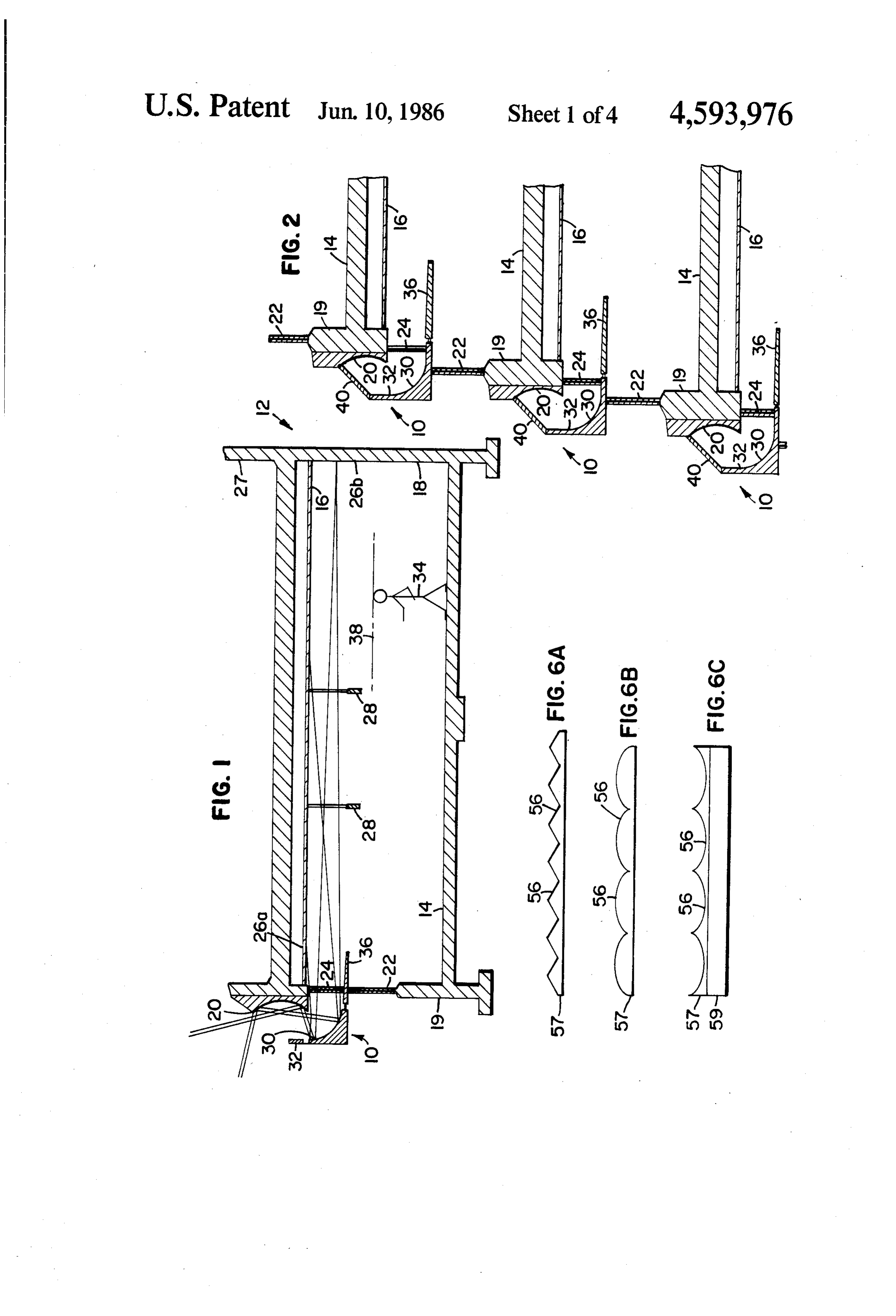
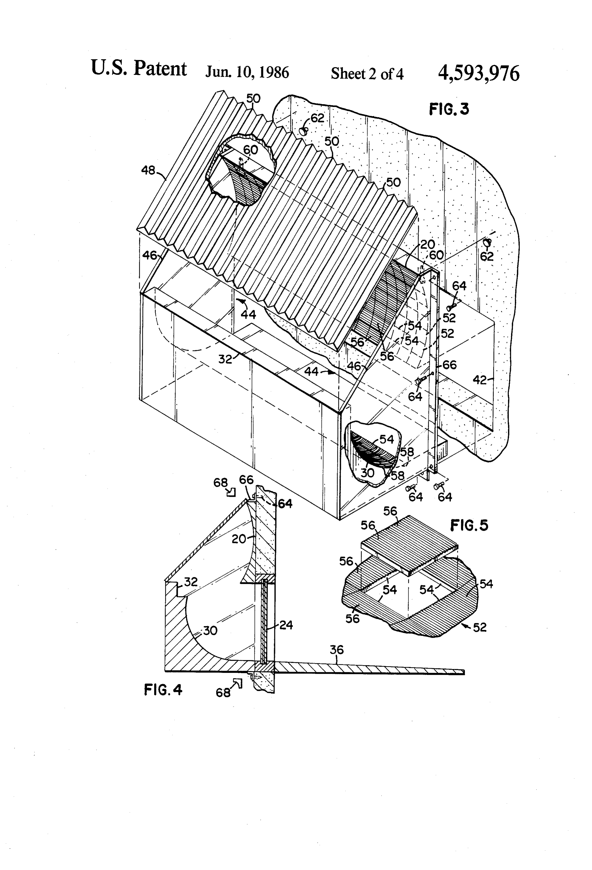
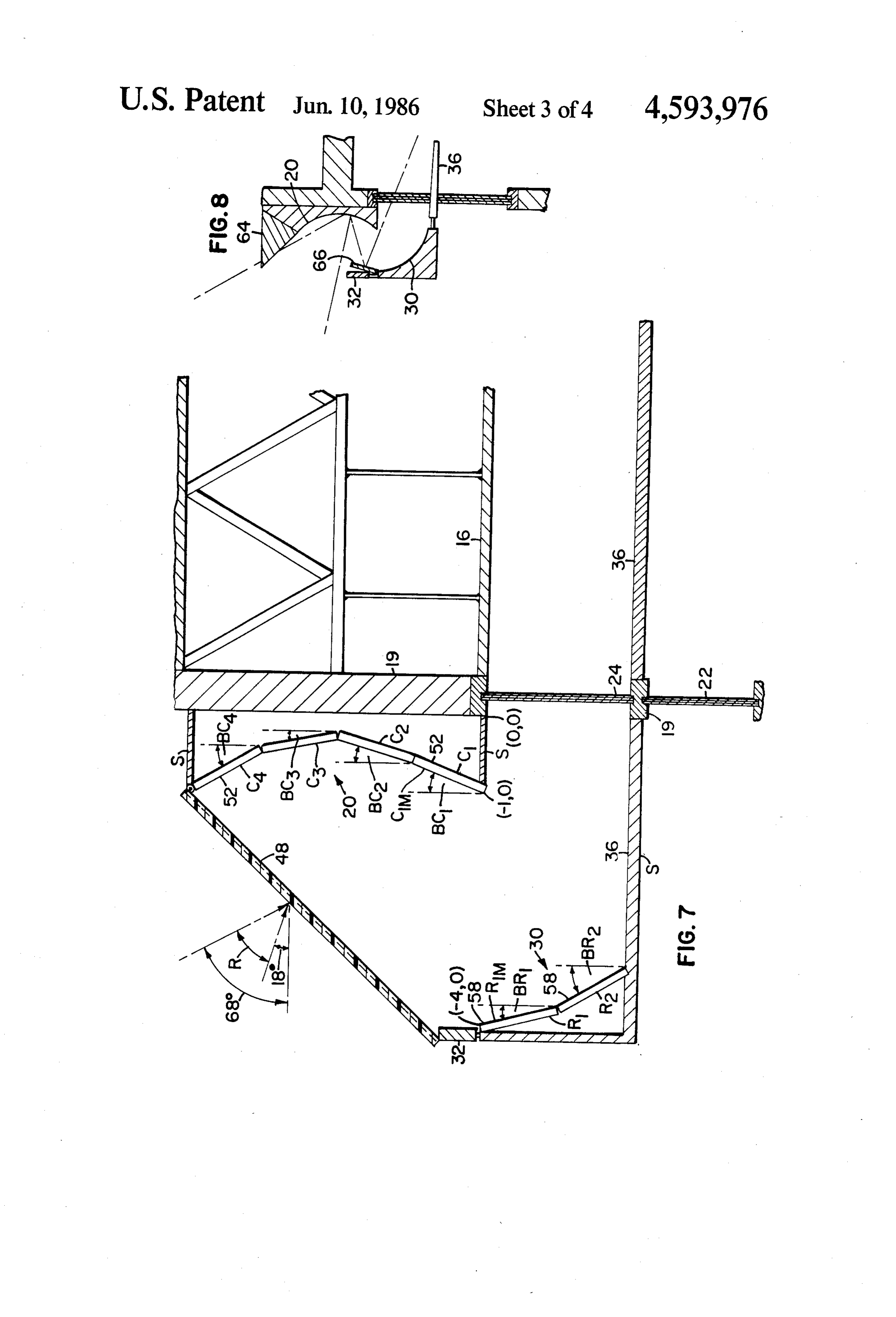
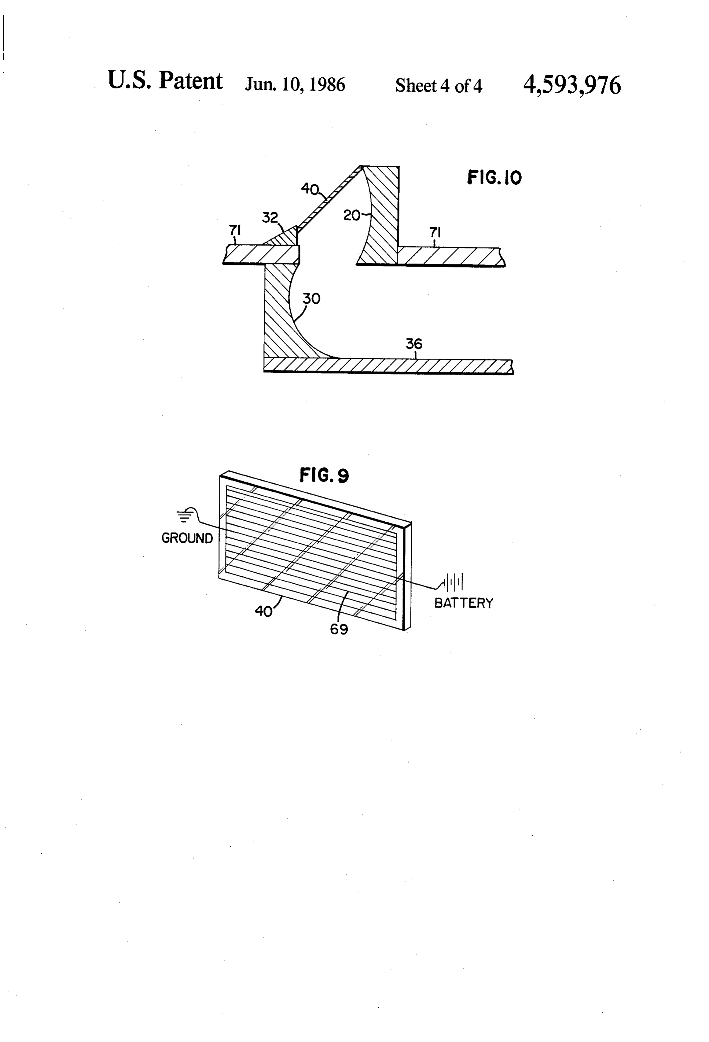
FIG. 9 shows a further optional embodiment of the
Page 2drawing sheetscan →
Page 3drawing sheetscan →
Page 4drawing sheetscan →
Page 5drawing sheetscan →
Page 6scan →
installed on successive floors of a building, with each
SOLAR LLUMINATION DEVICE device illuminating its respective floor area. The apparatus may further include a fresnel lens posi
TECHNICAL FIELD tioned between the collector and the sky to increase the The present invention relates to an apparatus for 5 solar azimuth angle of radiation which reaches the col concentrating and collecting solar energy for illumina lector. Further, end mirrors can be positioned against tion purposes within a structure. More particularly, the the ends of the collector/reflector pair to again increase invention relates to a stationary device which illumi the solar azimuth angle of light which enters the struc ture. The reflective surfaces of the collector and reflec nates an interior space through a side wall. 10 tor can be curved, or may be created in the shape of a BACKGROUND compound plane having two, three, four or more planar The use of solar energy for interior illumination has of surfaces. Each such planar surface may be in the shape been understood for centuries. Common window glass, a planar strip positioned to run along the length of the and skylights are known to virtually all styles of archi 15 Surface. Each strip may be made of individual tiles. The tecture and building design. Solar tracking devices have increasing surfaces reflective themselves, may include dispersion striations. A high angle shield and low angle been used to illuminate interior areas. These devices reflector may be installed to modify the intensity of require mechanical tracking systems for following the illumination sun's apparent motion across the sky. Stationary light the structureatmay certain solar angles, and the ceiling of shelves extending outwardly away from building side 20 number of opaquebeora translucent reflective or bright surface. A baffles may be in windows have also been used to increase solar illumina tion. stalled within the area to further prevent reflected il lumination from penetrating the predetermined hori
Refractive systems are also known to increase solar Zontal illumination within a building. An example of such a plane above the floor.
system is disclosed in the present inventor's prior patent 25 BRIEF DESCRIPTION OF THE DRAWINGS tracking reflective structure for vertically illuminating theFIG. 1 is a partial sectional view of an installation of present invention on the south wall of a structure.
an interior space is also disclosed at the University of FIG. 2 is a similar fragmentary sectional view show Minnesota Civil/Mineral Engineering Building in Min ing the installation of three such devices in a multistory neapolis, Minn. This device has two generally horizon 30 building.
tally extending reflective surfaces and provides diffuse FIG. 3 is a front and left side perspective view on an solar illumination through the roof.
The present invention provides solar illumination bodiment scale enlarged of an installation of an alternative em the invention, with portions exploded through a side wall, and is capable of illuminating a away and broken away.
large area such as a warehouse, or commercial space. 35 FIG. 4 is a fragmentary sectional view of a further The device allows solar illumination to effectively illu alternative embodiment.
minate each floor of a multifloor building, which is FIG. 5 is a partial perspective view of an alternative difficult or impossible with a vertical system. The pres embodiment of the invention on an enlarged scale ent invention is believed to be a true advance in the state showing a plurality of individual tiles lying in a com of the art as its structure and installation are simple, 40 pound planar surface economical, and versatile. Within the concept of the FIGS. 6a-6c are partial elevational views on a further present invention, the installation of a concentrator for enlarged scale of alternative forms of the reflective a given latitude is straight forward. A number of struc material shown schematically in FIG. 5. tures are present which allow the intensity of illumina FIG. 7 is a partial sectional view of another embodi tion to be controlled. 45 ment of the invention installed on a south facing wall. SUMMARY OF THE INVENTION FIG. 8 is a partial sectional view of the present inven tion illustrating yet another embodiment.
The present invention is an apparatus for concentrat FIG. 9 is a schematic perspective view of a portion of ing, and reflecting solar illumination for use in the inte the present invention showing still another optional rior of a building. The collector is made of a number of 50 embodiment.
individual components. A stationary reflective collec FIG. 10 is a partial sectional view of an installation of tor is installed longitudinally above a window or open again another embodiment of the present invention. ing in the building and is positioned to view the sky. A stationary reflector, again installed longitudinally on DETALED DESCRIPTION OF THE the outside of a building and positioned to receive direct 55 INVENTION solar energy reflected by the collector directs the sun's Throughout the following discussion, certain terms energy toward a target within the structure. A low shall be used to describe portions of the invention. angle shield prevents direct solar rays from entering, These terms may be given their ordinary meaning as unreflected, into the structure between the collector supplemented by the following definitions: collector; a and reflector so as to penetrate a horizontal plane a 60 reflective surface, on which direct solar rays are inci given distance from the floor. A shield extends gener dent and reflected to a reflector. In the preferred em ally horizontally and inwardly from the bottom of the bodiment of the invention the collector is an extended reflector. This structure prevents direct rays reflected curved or compound planar surface lying generally on by the collector and reflector from penetrating the the exterior of a building above a solar window or ac given horizontal plane. The given horizontal plane is 65 cess opening. The reflector is a reflective surface on typically spaced above the floor of the structure sub which rays reflected by the collector are incident and stantially the distance of the eye of an occupant stand reflected into a structure toward a target. In the pre ing on the floor. A plurality of such devices can be ferred embodiment of the invention, the reflector is an 7 extended curved or compound planar surface installed on the exterior of a building 12 which includes a space generally exterior of a building and positioned below to be illuminated having a floor 14, a ceiling 16, a back the collector, opposite and spaced away from the solar wall 18 and a front wall 19. The concentrator 10 is window. The target is an area within the structure to be installed on a wall which includes vision glass 22, and a illuminated, which lies generally away from the solar solar window 24. The collector 20 is a longitudinally window. In the preferred embodiment the target com extending generally curved or compound planar surface prises an area on the back wall and ceiling of the struc installed with its lower most region generally along the ture. The target has an apparent center which lies in the upper limit of the solar window 24. plane of the back wall. The apparent center may be The concentrator 10 also includes a stationary reflec behind an opaque surface such as the ceiling when 10 tive reflector 30 positioned to receive direct solar en viewed from the reflector. The low angle shield is an ergy reflected by the collector 20 so as to reflect such opaque structure defining a boundary of the entrance energy generally toward a target within the building 12. aperture. In the preferred embodiment, the low angle The target is generally a region of the ceiling 16 and the shield is affixed to the reflector, just above its upper back wall 18 between the points 26a on the ceiling 16 limit. The low angle shield prevents direct solar rays 15 and 26b on the back wall 18. The target has an apparent from entering, unreflected, into the structure between center at or near a point 27 on the back wall 18. The the collector and the reflector. The shield is an opaque apparent center 27 is behind the opaque ceiling 16 when structure having a reflective surface on the side nearest viewed from the reflector and is not visible from the the reflector. In the preferred embodiment the shield reflector. Rays striking the target will be scattered or extends generally horizontally from the bottom of the 20 diffused by the target and will be of an intensity suitable collector toward the target for a limited distance. The for illumination of the work area within the building. shield may be partially or completely inside the struc The reflector 30 is generally positioned outside of the ture or may be completely outside. The purpose of the building with a vertical dimension generally corre shield is to prevent reflected rays from being directed to sponding to the height of the solar window 24. The an area within the structure where they may be directly 25 lower most portion of the reflector 30 is installed oppo received by the eye of an occupant standing on the floor site the bottom of the solar window 24 with the upper of the structure. The reflective surface of the shield most region of the reflector 30 horizontally spaced from redirects such rays to the target area. the top of the solar window 24 and the bottom of the The combination of the reflector and collector form a collector 20.
trough area which may be bordered by end mirrors 30 A low angle shield 32 is installed above the reflector and/or one or more of the following: a snow cover or 30. The low angle shield 32 serves as a means for pre fresnel lens cover and a transparent thermal barrier in venting direct solar rays from entering the area to be the solar window. These features improve the operation illuminated without being reflected by the collector 10 of the present invention, but are generally not required and reflector 30. Such an unreflected ray could other within the principles of the invention. 35 wise pass between the collector and reflector and could A general familiarity with the apparent position of penetrate into the space so as to be perceived by the eye the sun in the sky is presumed. The apparent solar angle of an occupant 34 standing on the floor 14. Such a ray is dependent on the time of day, the season of the year, would be distracting to the occupant 34 as it would and the location of the observer on the earth. Within the constitute an uncomfortable glare of bright illumina following discussion, the solar zenith angle will be de tion.
fined as the angle of solar elevation above the horizon. A shield 36 is also included in the concentrator 10. This angle is dependent on the latitude of the location The shield 36 serves as a means for preventing direct from the equator and reaches its maximum value at rays reflected by the collector 20 and reflector 30 from noon on the day of the summer solstice. the solar azi penetrating the horizontal plane 38 spaced above the muth angle is the angle of horizontal solar deviation 45 floor substantially equal to the height of the eye of an measured from a horizontal line extending perpendicu occupant 34 standing on the floor 14. The shield 36 has larly from the collector. The value of this angle varies a reflective upper surface so as to reflect any rays inci between the apparent angle of the sun at sunrise and dent upon it toward the target area between points 26a sunset, and will differ throughout the year. and 26b.
It should be noted that throughout this discussion, the 50 Also shown in FIG. 1 are two baffles 28 which com invention will be described in reference to an installa prise longitudinally extending opaque or translucent tion on the south wall of a building in the northern panels suspended from the ceiling 16. The baffles 28 are hemisphere. As should be readily understood, the de not essential to the operation of the device, yet they vice can be advantageously installed on an east or west allow the shield 36 to be of a reduced dimension while wall of a building to function during periods of the day 55 effectively preventing reflected rays from penetrating when such a wall receives direct illumination. Installa the horizontal "eye level” plane 38. tion on a north wall in the northern hemisphere is possi In reference now to FIG. 2, a multistory installation ble, but will not generally receive substantial amounts is shown. Each floor 14 of the building includes a con of direct radiation and will not generally produce bright centrator installed on an exterior wall. Each concentra illumination within the structure. Corresponding appli 60 tor 10 provides illumination to the space on the floor on cations in the southern hemisphere are also possible. which it is installed. - Throughout the following description reference will Each story of the multilevel structure has a floor 14, be made to the drawings and the same numerals will be a ceiling 16 and a front wall 19. Each front wall 19 has used throughout the several views to indicate the same vision glass 22 and a solar window 24. A snow cover or or like parts of the invention. 65 angled transparent panel 40 may be installed at locations Referring now to FIG. 1, the concentrator 10 in which receive appreciable annual snow falls. The snow cludes a stationary reflective collector 20 positioned to cover 40 is installed along the length of the collector 20, view a portion of the sky. The collector 20 is installed spanning the space between the collector 20 and the 8 low angle shield 32. The snow cover 40 keeps snow, FIG. 4 shows a retrofit type installation similar to dirt and debris off of the reflective surfaces. that shown in FIG. 3, although the surfaces shown in In reference now specifically to FIG. 3, another em FIG. 4 are not compound planes. The collector 20 bodiment of the present invention is shown. In this shown in FIG. 4 has a radius of curvature which curves embodiment, the collector 20 and reflector 30 are only 5 more sharply toward the bottom. This can be described as long as the window 42 over which they are installed. as an arc whose radius decreases from top to bottom as This version of the invention may particularly be appro seen in FIG. 4. Similarly, the reflector 30 of FIG. 4 has priate for retrofit applications or installation of the de a decreasing radius of curvature which decreases from vice on an older building not specifically designed for bottom to top when viewed in FIG. 4. This curved solar illumination. Because of the limited length of the 10 surface can be comprised of a very large number of 20 collector and reflector 30, the trough area 44 be small planar tiles or a curved reflective surface. tween these structures is bounded by a pair of inwardly In both FIGS. 3 and 4 there is no vision glass shown. facing reflective mirror end panels 46. These panels will In this type of installation, the occupant within the increase the azimuth angle for solar illumination which building could not normally see the horizon of objects can enter the window 42. 15 outside of the building. FIG. 3 does not include a pane This embodiment further includes a solar azimuth of glass installed in the window 42. Such a plane of glass angle increasing fresnel lens 48 affixed to lie over the is shown in FIGS. 1, 2 and 4 for example. The embodi entrance aperture of the device. In this embodiment, the ment shown in FIG. 3 does not include a barrier be entrance aperture is defined by the upper edges of the tween the interior space and the trough area 44. In this collector 20, the low angle shield 32 and the end panels 20 case the lens 48 serves as part of the thermal barrier 46. The lens 48 has a plurality of fresnel type ridges 50 between the interior and exterior of the structure. which run from the upper limit of the low angle shield FIGS. 6A, 6B, and 6C show alternative forms of the 32 to the upper limit of the collector 20. In this configu actual contour of the striations shown in FIGS. 3 and 5. ration, the zenith angle necessary for a ray to enter the The striations may be peaked (FIG. 6A) or convexly building is substantially unaltered, while the azimuth 25 curved (FIG, 6B) or concavely curved (FIG. 6C). The angle from side to side or rays which will enter the striated surface 57 may be mounted on a backing 59 as building is substantially increased by the end panels 46 shown in FIG. 6C. The reflective surface can also be and the lens 48. "pebbled' (not shown in the drawings) which would It should be noted that the collector in this embodi simultaneously increase both the horizontal and vertical ment is comprised of a compound planar form including 30 components of reflected rays. Suitable striated reflec eight rows or strips 52 of horizontally extending reflec tive material is commercially available from the 3M tive material. Each strip 52 or row of material is itself company in St. Paul, Minn.
comprised of a number of generally square planar tiles SPECIFIC INSTALLATION GEOMETRY 54. Each such tile includes a number of striations 56 generally lying parallel to each other. These striations 35 In reference now to FIG. 7, a specific installation for 56 serve to increase the angle of diversion of reflected a site at a latitude of 45° north is shown. The installation rays. (See FIG. 5.). is on a south wall which includes a solar window 24 and As incoming solar illumination generally diverges at vision glass 22. The collector 20 includes four discrete an angle of approximately degree of arc, increasing planar strips 52 of reflective material designated C1, C2, this angle of divergence is important to prevent "oil 40 C3 and C4. The planar surfaces are mounted in abutting canning' type reflected illumination. Striations of the relationship along their edges. Each strip of material is type shown can readily increase this divergence to ap installed at an angle Beta with respect to the vertical. proximately 10'. As the striations on the collector 20 For example, the installation angle of C1 is designated run generally horizontally, they increase the vertical Beta C1. The installation angle of each strip or row is divergence angle of the reflected light. The horizontal 45 different from the installation angle of the abutting divergence remains generally unchanged by the stria strips or rows. Similarly, the installation angle for col tions on the collector 20. lectors C2, C3 and C4 are designated as Beta C2, Beta C3 The reflector 30 also includes striations 56 which run and Beta C4.
along the generally curved surface in a vertical direc In this embodiment, the reflector 30 comprises a com tion. The reflector 30 is itself a compound planar struc 50 pound planar surface having two planar strips 58 desig ture having a number of horizontally extending strips 58 nated R1 and R2. The installation angles of these sur or rows each composed of planar square tiles 54. The faces from the vertical have been designated as Beta R1 striations on these reflector tiles run generally vertically and Beta R2 respectively. The upper most limit of re on the reflector and serve to increase the horizontal flector strip R1 lies generally horizontally spaced from divergence angle of the reflected illumination. The 55 the upper portion of the solar window 24 in a plane combination of horizontally oriented striations 56 on which includes the lower most limit of the collector the collector 20 and vertically oriented striations 56 on strip C1. As described above, each of the collector and the reflector 30 serves to increase the divergence of reflector strips 58 are in abutting relationship and can be reflected illumination to a cone of illumination diverg made of planar tiles affixed in side-to-side relationship. ing at approximately 10' of arc from side to side and 60 Such tiles may include striations which can run parallel from top to bottom. to the strips (as shown in FIG. 5) or may run perpendic The embodiment shown in FIG. 3 includes an instal ularly to the strips. FIG. 5 would show such an installa lation means having a key hole arrangement 60 for tion if each of the tiles were rotated 90' to that shown. hanging the structure on a lug 62 and includes affixment In reference again to FIG. 7 a low angle shield 32 is bolts 64 and a flange or mounting bracket 66. This 65 installed above the reflector 30 upper limit. A fresnel bracket may be covered with a molding 68 or other lens 48 is installed between the top of the low angle insulating material for aesthetic and energy conserva shield 32 and the upper most portion of the collector 20. tion purposes (see FIG. 4.). A suitable structure (S) is included to affix the reflector 9 and collector to the front wall 19. A shield 36 is installed It should be noted that the installation geometry set between the lower most limit of the reflector 30 and the forth herein specifies specific installation angles for the building wall 19. The shield 36 also extends inwardly collector rows 52 and the reflector rows 58. As the sun from the bottom of the solar window 24. has an apparent motion through the sky which is contin The calculations for an installation at approximately uous, the actual solar azimuth and zenith angles for 45 degrees north latitude are set forth below. Starting incoming rays are constantly changing. Consequently, with a typical space to be illuminated, as a building the actual path of incoming solar rays varies over time. having a south facing window or front wall 19 and a The solar collector 10 will function throughout this back or north wall approximately 40 feet therefrom, the period.
size of the space to be illuminated is known. Assuming 10 We know that for the installation shown in FIG. 7, that vision glass 22 is installed in the south or front wall the collector segment C1 has a midpoint CM lying on 19 from approximately 3 foot, six inches off the floor to the ordinate system approximately at location approximately 7 feet off the floor, the solar window 24 (-1,+0.5). C1M represents the vertical midpoint of the can be installed between approximately 7 foot, six horizontally extending surface C1 shown in section in inches from the floor to approximately 9 foot, six inches 15 FIG. 7. All of the rows have such vertical midpoints. off the floor. We also know that with this arrangement, the first seg For any given latitude, the maximum solar zenith ment of the reflector (placed three units to the south of during summer solstice and minimum solar zenith dur the bottom of collector 1 has a midpoint R1M located ing winter solstice can be determined from solar tables. approximately at ordinate (-4, -0.5). With the solar For an installation at approximately 45 north latitude a 20 design angle Alpha 1 = to 61.75 degrees we can deter typical winter solstice zenith angle will be approxi mine the proper installation angle Beta C1 for collector mately 22 degrees above the horizon. At such a loca row C1. It is desired to reflect this 61.75 degree ray from tion the summer solstice zenith angle will be approxi CM to R1M. Using trigonometry, the following formula mately 68. For such a sight, it is appropriate to concen applies.
trate and admit into the structure all direct solar rays 25 having a zenith angle between 18' and 68 above the horizon. With this range (R) of solar acceptance, the Y CM - Y R1f concentrator will be operative on virtually all days of ARCTAN (i.CM X RIM ) PHI CM RM the year.
The collector 20 has four segments or collector strips 30 Here PHICMRM=the angle from the horizontal of 52 (C1-C4). Since it is anticipated that solar zenith an a ray gles between 18 and 68' will be accepted at this site, knownwhich will travel from CM to R1M. Filling in the each of the four segments will generally be responsible can calculate PHI: coordinates for CM and RM we approximate for collecting approximately or one quartile of this 50 vertical spread of solar illumination (R). Consequently, 35 each segment or strip 52 will be responsible for collect ing and reflecting approximately 12" of the vertical ARCTAN ( - 1 - (-4) ) = TAN () = solar illumination.
For the purposes of understanding the relative posi 1843 - PHI CM R1M tions of the components, the structure can be superim posed on an ordinant system having its origin (0,0) at We can round this angle to the nearest so that PHI the top outside corner of the solar window 24. The bottom most portion of the first collector panel C can C1M RM = 18.5
Knowing this angle, the correct C1 installation angle then be installed one unit away from the origin (-1,0). Beta C1 is calculated as follows: The units of measurement are purely arbitrary and are 45 assumed to be the width of each strip 52 in the collector ALPHA – PHI CR panel 20. The top portion of the first reflective strip R1 BC1 = 2 1M 14 is located three units south (-4,0) of the bottom of the first collector panel C1.
The solar design angles Alpha 1, Alpha 2, Alpha 3 50 Where Alpha 1 is the angle of the incoming midray and Alpha 4 will represent the solar azimuth angle of a described above, Beta C1 is determined to be 21.625. ray in the middle of each 12 degree quartile of the total which can be rounded to 21.5. By convention, Beta range (R) of vertical solar illumination. Since four col will be measured from the vertical with the clockwise lector segments are used, and the range (R) of solar rays direction as positive and the counter clockwise direc to be collected has been chosen between 18 and 68, 55 tion as negative.
Alpha 1 = 61.75, Alpha 2=49.25, Alpha 3=36.75, In order to calculate the installation or Beta angle for and Alpha 4=24.25. These figures were obtained by R1 the apparent center of the target area must be se subtracting 6.25 from the 68 maximum solar angle (to lected. The target comprises the surface of the back calculate the solar angle of a midpoint ray within the wall and the ceiling to be illuminated. (See the area first 12 degree quartile of the total 50 spread) and then 60 between points 26a and 26b in FIG. 1.). Generally, this subtracting 123 degrees from this midpoint ray to calcu area can be thought of as the area illuminated by a late each successive midpoint ray in the second, third wedge of light spread by the collector/reflector pair and fourth quartiles of this 50° spread. The solar angles and having a wedge spread angle of between 1 and 2 Alpha 1 through Alpha 4 will be used to determine the times the solar segment (in this case 12). Since it is angle of installation of each segment of the collector 20 65 desirable to direct the incoming illumination above a needed to reflect the midpoint ray within any given plane substantially the height from the floor of the eye quartile to the desired portion of the reflector 30 for of an observer or occupant standing on the floor (plane rereflection toward the target within the building. 38 in FIG. 1), the reflected illumination should be aimed 10 at an apparent target center which lies at a point on the aim Alpha 1 toward the target. C2 would likewise coop back wall somewhat above the ceiling. A suitable loca erate with R2 to aim Alpha 2 toward the target and so tion for the apparent center of the target can be found at on. The number of actual collector segments and the coordinate (40,7) not shown in FIG. 7 due to space number of actual reflector segments will determine the limitations, but shown approximately at point 27 in efficiency and cost of the actual installation. FIG. 1. Determination of the PHI angle for R1 to aim Turning now to FIG. 8, an installation at a location the beam it receives from C1 toward the center of the closer to the equator is shown schematically. This in target is found with the following formula. stallation has a collector 20 and reflector 30 pair, as well as a low angle shield 32 and a shield 36. A high angle
O shield 64 is also installed above the upper limit of the
PHI R1T = ARCTAN ( 40 - (-) - j = collector 20. The high angle shield 64 shades a portion of the collector 20 during periods of extreme high solar angle illumination. The high angle shield will serve to decrease amount of incoming solar illumination warmest or hottest part of the day. This may be desirable to reduce the maximum incoming light
For this calculation the resulting 9.67 angle is between 11:00 a.m. and 1:00 p.m. during the summer rounded to 9.5. The installation or Beta angle for R1 is months. The high angle shield will not shade the entire now calculable.
20 collector even during these periods and sufficient illum ination will still be provided to the work space. During -PHI R1T - PHI C R1 the winter months, the high angle shield 64 would not BETA R1 = -- shade any portion of the collector 20 even at noon. Thus, the high angle shield is installed to seasonally
Beta R1 is consequently: 25 modify the peak solar illumination within the structure. FIG. 8 also illustrates a supplementary low angle reflector 66. This device is installed between the low angle shield 32 and the collector 20. The installation or
Beta angle for the supplementary low angle reflector 66
Thus, the installation angle for Beta R1 is -14. is greater than that for the first segment of the reflector Since the location of C1 and R1 have been chosen by placing the bottom edge of C1 at location (-1,0) and the (R1). The supplementary low angle reflector 66 serves top edge of R1 at location (-4,0), and we have calcu angle directillumination to increase entering the structure with low lated the installation angles for these components, it is tor 66 will increase illumination in thelowearly rays. This supplementary angle reflec morning now possible to calculate the location of the top edge of 35 and particularly during winter months. C1, and bottom, edge of R1.
The combination of the high angle shield 64 and the
CTOP = (-1, + SIN Beta C, 0 + COS Beta C) supplementary low angle reflector 66 will serve to aver = (-63), -93) age out the illumination of the interior of the structure R1BOTTOM = (-4 - (SIN - 9.5), 0 - (COS - 9.5) throughout the day and throughout the year.
FIG. 9 shows a further optional embodiment of the
With the top of C1 and the bottom of R1 known, present invention. In this embodiment aheating element calculation of the PHI and Beta angles for C2 proceed in 69 is affixed to the snow cover 40. The heating element the same manner as set forth above. Alpha 2 is used for 69 can be embedded into the snow cover 40 or applied the calculations for C2. The Alpha 2 ray is aimed at the 45 to the surface thereof. The heating element may operate midpoint of R1. Beta C2 works out to be 16.5". By use of on direct current or alternating current, and like the this angle and the exact position of CTOP, CTOP can defroster unit common on many automobiles can melt be calculated. Using this point as the bottom for C3, and outside snow and ice as well as vaporize condensation using Alpha 3 as the incoming solar ray for C3, PHI C3 on either side of the snow cover. The heating element is R2 and Beta C3 are calculated. 50
In this installation, C1 and C2'aim' the Alpha 1 and made of electrically conductive material having enough Alpha 2 rays respectively at R1. C3 and C4"aim” Alpha resistance to generate heat, yet is of a small dimension 3 and Alpha 4 rays respectively at R2. The installation the so as not to interfere with the light transmitted through or Beta angles of R1 and R2 are determined to reflect snow cover 40. A similar heater can be installed on their respective incoming rays (reflected Alpha 1 and a lens cover 48.
Alpha 2 for R1, and reflected Alpha 3 and Alpha 4 for FIG. 10 shows yet another installation of the present R2) generally toward the midpoint (40,7) of the target. invention. Here the collector 20 and reflector 30 are Performing these calculations, the geometry of an in installed on opposite sides of an extended opening in the stallation at latitude north 47 is set forth in FIG. 7 and roof 71 of a building. The installation includes a low the accompanying chart below. angle shield 32 and a shield 36, as well as a snow cover BC1=21.5 40. In this installation the snow cover serves as the BC2 = 16.5° thermal barrier between the interior of the structure and BC3 = - 10.5 the outdoor environment.
BC4 = -29.5 It should be noted that with this type of installation, BR1 = -14' the solar energy transmitted through the roof 71 is cast BR2 = -30.5 primarily toward the right hand portion of the FIG. 10. It should be noted that it is entirely possible to have Another installation of a device similar to that shown in an equal number of collector segments and reflector FIG. 1 on the front wall of the structure can provide segments. In such a case C1 and R1 would cooperate to illumination from the front wall (not shown in FIG. 10)
Page 11scan →
of the structure to the area below the opening in the window positioned on said front wall near said roof 71. ceiling;
In fact, installations like that shown in FIG. 10 can be a stationary reflective reflector positioned to receive placed at intervals of every 80 to 100 feet from the front direct solar energy reflected by said collector and wall to illuminate interior areas of vast dimensions, all 5 affixed in a position with its upper most limit sub within the spirit and teaching of the present invention. stantially horizontally spaced from the lower most Several embodiments of our invention have been set limit of said collector, so that said reflector reflects forth herein. In light of the above-teachings it will be energy from said collector toward a target within appreciated that several variations of the disclosed em said structure;
bodiments are possible. For example, the selection of 10 a low angle shield means for preventing direct solar virtually any number of planar collector segments and rays from entering, unreflected into the structure planar reflector segments are possible. Similarly, use of between said collector and said reflector to pene a smoothly curced, longitudinally extending collector trate a horizontal plane positioned above said floor surface and a similar reflector surface are possible. The a distance substantially equal to the height of the curvature of these surfaces and the angles of lines 15 eye of an occupant standing on said floor, said low drawn tangent to the surfaces at given points can be angle shield affixed to said reflector above said calculated as set forth with respect to compound planar lower most limit of said collector; and surface. Also, variations in the spacing of the reflective a shield means for preventing direct rays reflected by surfaces and attachment of lens or snow covers, low said collector and said reflector from penetrating angle shields, secondary reflectors and shields and the 20 said horizontal plane, said shield means including a like can be made. Further, the attachment and specific generally horizontally extending panel with a re location of high angle shields, supplementary low angle flective upper surface, said panel affixed to said reflectors, and baffles and the like can be made. Thus front wall just below said window. the invention is not to be construed as limited to the 3. The concentrator of claim 2 wherein said collector specific embodiments shown in the drawings but is to be 25 and reflector are each extended curved surfaces having limited only by the broad general meanings of the foll ends, and further comprising a pair of end mirrors posi lowing claims. tioned adjacent said ends of said collector and reflector We claim: with the reflective sides facing toward said collector 1. a solar concentrator for illuminating the interior of and reflector and substantially perpendicular to said a building through a side wall thereof, said concentra 30 front wall of said building.
tor, comprising: 4. The collector of claim 1 further comprising a fres a stationary reflective collector located to view the nel lens positioned between said collector and the sun to sky and having a plurality of discrete planar collec increase the solar azimuth angle of direct rays which tor surfaces mounted in abutting relationship, each reach said collector.
said collector surface installed at an angle with 35 5. The concentrator of claim 1 wherein said collector respect to the vertical different from said angle of includes a plurality of dispersion increasing striations installation of said abutting collector surfaces; each lying substantially in a horizontal direction. a stationary reflective reflector positioned to receive 6. The concentrator of claim 1 wherein said reflector direct solar energy reflected by said collector and includes a plurality of dispersion increasing striations oriented to reflect such energy toward a target 40 each lying substantially in a vertical plane. within said building, said reflector having a plural 7. The concentrator of claim 1 wherein said building ity of discrete planar reflector surfaces each said further includes a reflective ceiling.
reflector surface mounted in abutting relationship, 8. The concentrator of claim a further comprising at each said reflector surface installed at an angle with least one baffle suspended at a distance from said ceiling respect to the vertical different from said angle of 45 substantially equal to the distance of said shield means installation of said abutting reflector surfaces; from said collector, said baffle running substantially a low angle shield means for preventing direct solar parallel to said side wall and being of a translucent or rays from entering unreflected into said building opaque material.
between said collector and said reflector and pene 9. The concentrator of claim 1 further comprising a trating a horizontal plane above the floor of said 50 high angle shield means affixed above the upper limit of building, said horizontal plane spaced from said said collector for shading a portion of said collector floor a distance substantially equal to the height of during periods of high solar angle.
the eye of an occupant standing on the floor of said 10. The concentrator of claim 1 wherein said reflec building, said low angle shield means including an tive collector surface comprises a compound planar opaque material and being affixed to said reflector; 55 surface composed of individual planar reflective tiles. and 11. The concentrator of claim 1 wherein said reflec a shield means for preventing rays reflected by said tive reflector surface comprises a compund planar sur collector and said reflector from penetrating said face composed of individual planar reflective tiles. horizontal plane, said shield means affixed to said 12. The collector of claim 1 further comprising a building and extending in a generally horizontal 60 supplementary low angle reflector having a reflective direction. surface positioned generally between said low angle 2. A solar concentrator for illuminating a portion of shield and said collector and installed at an angle with the interior of a structure having a ceiling, a floor, and respect to the vertical greater than the angle with re front, back and side walls, said concentrator compris spect to the vertical of the upper most portion of said 1ng: 65 reflector.
a stationary reflective collector positioned to view a 13. A solar concentrator for illuminating the interior portion of the sky, said collector affixed to the of a building with direct solar illumination from a range exterior of said building above a window, said of illumination having a zenith angle between the maxi 12 mum summer solstice zenith and less than the maximum range of illumination generally toward the center winter solstice zenith angle, said concentrator compris of said target within said building; and Ing: said second reflector surface installed at an angle with a stationary, longitudinally extended reflective col respect to the vertical so as to reflect said reflected lector having first, second, third and fourth dis 5 rays within said third and fourth quartile of said crete planar surfaces, each said surface installed in range of illumination generally toward the center abutting relationship to the adjacent collector sur of said target within said building. face, each said surface being installed at an angle 14. The concentrator of claim 13 further comprising: with respect to the vertical; a low angle shield means for preventing direct solar a stationary longitudinally extending reflective re 10 rays from entering unreflected into said building flector having first and second discrete planar re between said collector and said reflector and pene flector surfaces, said reflector surface installed in trating a horizontal plane above the floor of said abutting relationship and each reflector surface building, said horizontal plane spaced from said installed at an angle with respect to the vertical; floor a distance substantially equal to the height of said first collector surface installed at an angle with 15 the eye of an occupant standing on the floor of said respect to the vertical so as to reflect a direct ray building, said low angle shield means including an within the middle of the upper most quartile of said opaque material and being affixed to said reflector. range of illumination toward the vertical midpoint 15. the concentrator of calin 14 further comprising: of said first reflector surface;
said second collector surface installed at an angle 20 a shield means for preventing rays reflected by said collector and said reflector from penetrating said with respect to the vertical so as to reflect a direct horizontal plane, said shield means including a ray within the middle of the second upper most panel affixed to said building and extending in a quartile of said range of illumination toward the vertical midpoint of said first reflector surface; generally horizontal direction. said third collector surface installed at an angle with 25 16. The concentrator of claim 15 further comprising a respect to the vertical so as to reflect a direct ray fresnel lens means including a lens positioned between within the middle of the third upper most quartile the collector and the sun for increase the range of solar of said range of illumination toward the vertical azimuth angles of direct rays which reach said collec midpoint of said second reflector surface; Ot.
said fourth collector surface installed at an angle with 30 17. The concentrator of claim 13 further comprising a respect to the vertical so as to reflect a direct ray plurality of dispersion increasing striations lying in a within the middle of the fourth upper most quartile substantially horizontal direction on said collector sur of said range of illumination toward the vertical faces.
midpoint of said second reflector surface; 18. the concentrator of claim 13 further comprising a said first reflector surface installed at an angle with 35 plurality of dispersion increasing striations lying on a respect to the vertical so as to reflect said reflected substantially vertical direction on said reflector surface. rays within said first and second quartile of said six 32 3 e
Page 13scan →
United states patent and trademark office
Certificate of correction
NVENTOR(S) : David J. Bennett and David A. Eijadi It is certified that error appears in the above-identified patent and that said Letters Patent is hereby Corrected as shown below:
Column line ll, "20 collector" should be --collector 20--;
Column line 37, after " (- . 63" delete the parenthesis; Column line 13, delete "curced" and insert -- curved--; Column line 29, delete "a" and insert --A--; Column line 42, "includes" should be -- includes--; Column line l2, "surface" should be -- surfaces--; Column line 8, "the" should be --The--;
Column line l8, "calim" should be -- claim--; Column line 34, "the" should be --The--;
Abstract, line ll, "space" should be -- spaced--.
Signed and Sealed this
Twenty-eighth Day of October, 1986
Seal
Donald j. quigg
Attesting Officer - Commissioner of Patents and Trademarks
Page 14scan →
United states patent and trademark office
Certificate of correction
NVENTOR(S) : David J. Bennett and David A. Eijadi It is certified that error appears in the above-identified patent and that said Letters Patent is hereby corrected as shown below:
Column 5, line ll, "20 collector" should be --collector 20--; Column 5, line 26, "or" should be --of--;
Column 6 line l4, "of" should be -- or--;
Column 9, line 37, after " (-.63" delete the parenthesis; Column ll, line l3, delete "curced" and insert -- curved--; Column ll, line 29, delete "a" and insert --A--; Column l2, line 42, "includes" should be --includes--; Column l3, line l2, "surface" should be --surfaces--; Column l4, line l8, "the" should be --The--;
Column 14, line l8, "calim" should be -- claim--; Column 14 line 34, "the" should be --The--;
Abstract, line ll, "space" should be -- spaced--.
Signed and Sealed this
Twenty-eighth Day of October, 1986
Seal
Attest:
Donald j. quigg
Attesting Officer - Commissioner of Patents and Trademarks
Provenance
- Collection
- Patents citing this work
- Pages
- 14
- Method
- pdftotext (the PDF's own text layer) + pdftoppm 300dpi page scans
- Patent office record
- patents.google.com →
- Source
- Google Patents citing-documents table
- Assignee
- Bennett, Ringrose, Wolsfeld, Jarvis, Gardner, Inc.
- Published
- 1986-06-10
- Transcribed from
- patentimages.storage.googleapis.com →