

patent · US4602614A
Hybrid solar/combustion powered receiver
29 July 1986
Text
Page 1bibliographic recordscan →
United States Patent (19)
Percival et al.
(54) HYBRID SOLAR/COMBUSTION POWERED
RECEIVER
Inventors: Worth H. Percival, Oakton; David N. Wells, Arlington, both of Va.
Assignee: United Stirling, Inc., Alexandria, Va.
Int. Cl. ................................................. F24J 3/02 52 U.S. C. .................................... 126/427; 126/448;
2,874,543 2/1959 Culver ................................... 60/67 3,861,146 l/1975 Lynch et al. .......................... 60/524 3,927,659 12/1975 Blake et al. ......................... 126/27 3,942,324 3/1976 Johansson et al. . ... 60/524 X 4,044,559 8/1977 Kelly ............... ... 60/517 X 4,069,670 1/1978 Bratt et al. ............................ 60/517 4,078,548 3/1978 Kapany ............................... 126/271 4,079,591 3/1978 Derby et al. ........................ 126/451 4,085,588 4/1978 Reams et al. ......................... 60/517 4,277,942 7/1981 Egnell et al........................... 60/517 4,345,426 8/1982 Egnell et al........................... 60/517
4,398,391 8/1983 English, Jr. ....................... 60/676 X
NNA,
4,414,812 11/1983 Parry ................................... 126/427
OTHER PUBLICATIONS
"Dish Stirling Solar Receiver Program Final Report',
FIGS. 1 and 2.
Primary Examiner-Samuel Scott
Assistant Examiner-Carl D. Price
Attorney, Agent, or Firm-Finnegan, Henderson,
Farabow, Garrett & Dunner
An improved hybrid solar/combustion powered re ceiver, for use e.g. with a hot gas engine, the receiver being of the type having a housing and an aperture for admitting solar radiation to the cavity defined by the
housing. The improved receiver includes a heat ex changer within the cavity and having the tubes tangen tially spaced; multiple burners for providing a combus tion gas flow path during combustion powered opera tion between and around the portions of the tubes upon which solar radiation impinges; and a fused silica, inter nally mounted window to seal the aperture against com
bustion gas leakage out of the receiver.
1 Claim, 2 Drawing Figures
Drawings
Page 2drawing sheetscan →
Page 3drawing sheetscan →
Page 4scan →
array and being spaced apart, the axis of the conical
HYBRID SOLAR/COMBUSTION POWERED heater pipe array being in line with the aperture; the gas RECEIVER burners being positioned for inducing a flow of combus
Background of the invention
tion gases within the receiver cavity between substan 5 tially the entire portion of the length of each of the 1. Field of the Invention individual spaced apart heater pipes of the conical array The present invention relates to an improved hybrid upon which the solar radiation impinges; and means for solar/combustion powered receiver for providing ther preventing thermal energy losses from the cavity result mal energy for use such as, for example, by a hot gas O ing from the escape of combustion gases through the engine. aperture during gas power operation. 2. Description of the Prior Art Preferably, the thermal energy convection prevent "Solar only” receivers typically function to convert ing means includes window means for sealing the aper solar radiation to heat energy for use, for instance, in ture while transmitting solar radiation. hot gas engines e.g. of the Rankine, Stirling, or Brayton The accompanying drawing which is incorporated types or another apparatus requiring thermal energy 5 in, and constitutes a part of, this specification, illustrates input. "Hybrid' receivers typically have the solar en one embodiment of the invention and, together with the ergy input augmented and/or supplanted by an auxili description, serves to explain the principles of the in ary energy source, such as combustion of natural gas, vention.
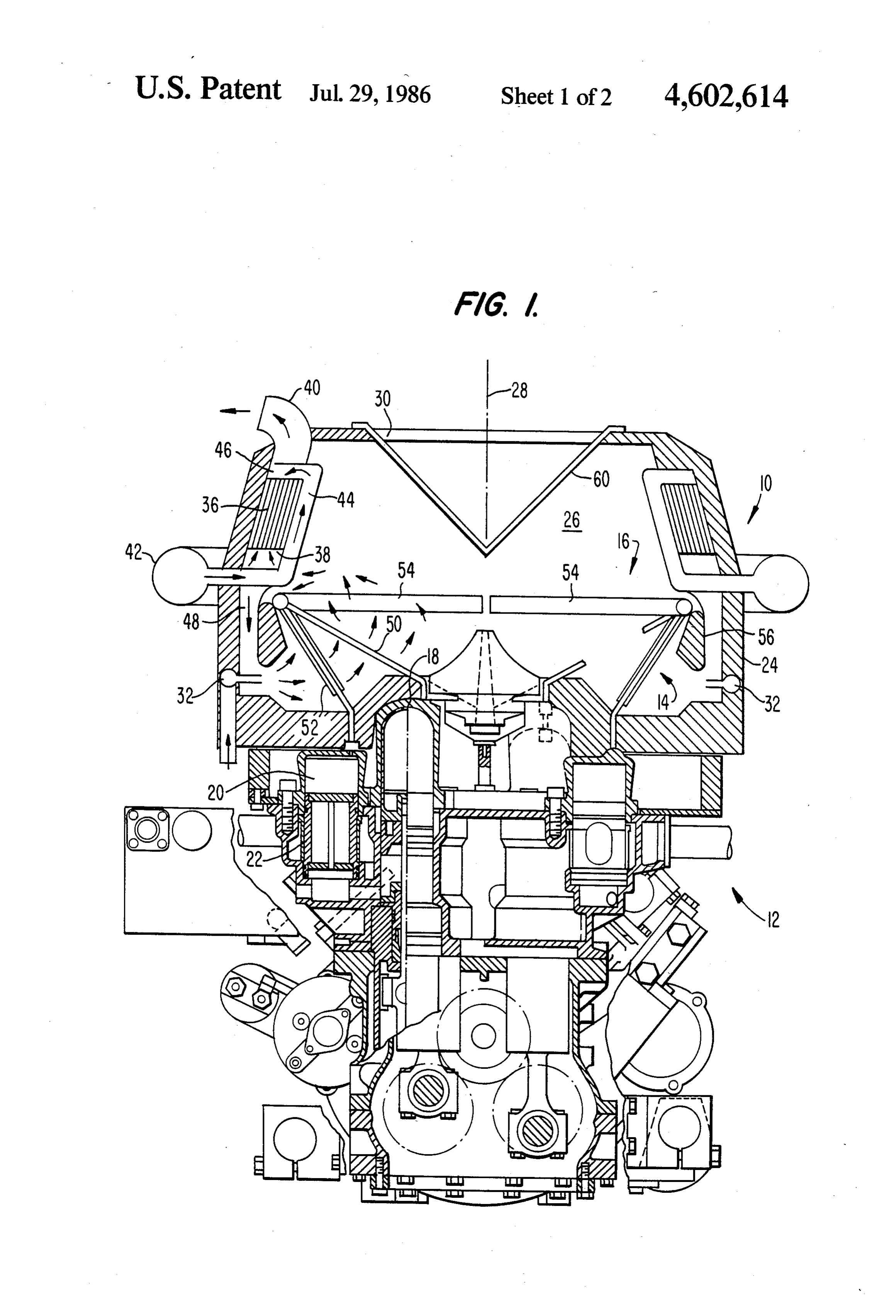
for use during periods of darkness or periods of low 20 insolation (e.g. cloudy days). BRIEF DESCRIPTION OF THE DRAWING A conventional hybrid solar/gas powered receiver is FIG. 1 is a schematic cross-section of an improved that proposed in the "Dish Stirling Solar Receiver Pro hybrid solar/gas powered receiver made in accordance gram Final Report', document No. ER 79917-3, Dec. with the present invention and shown being utilized in 15, 1980, drawing No. 79917001. That receiver included a generally cylindrical insulated housing with an aper 25 conjunction and with a hot gas engine of the Stirling type;
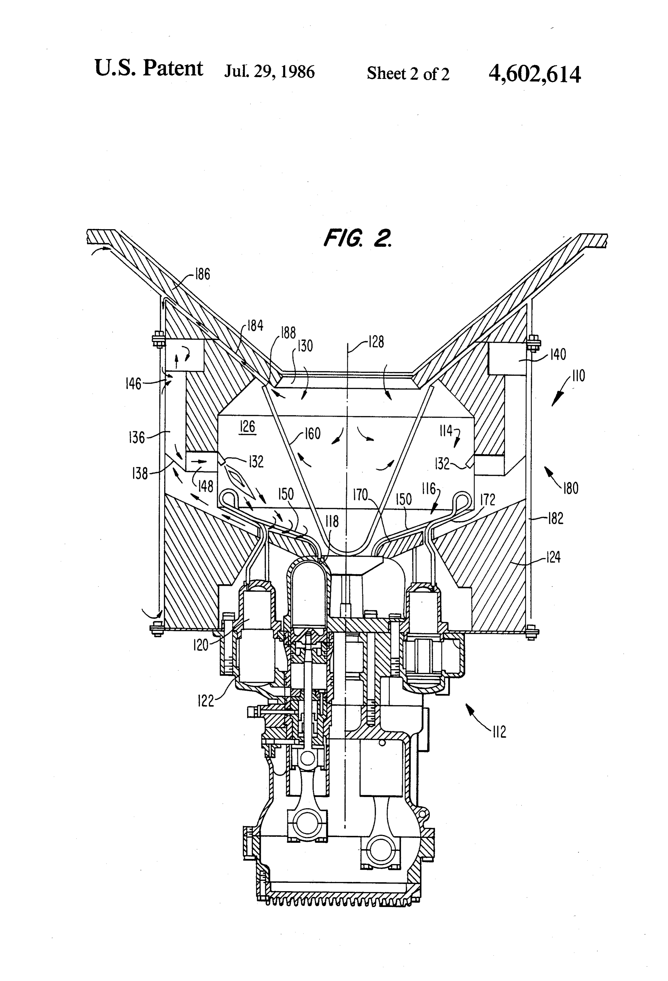
ture at one axial end and a conical heat exchanger at the FIG. 2 is a variation of the improved hybrid receiver other axial end. The heat exchanger, in particular, was embodiment shown in FIG. 1. formed from a plurality of tubes partially imbedded in a Reference will now be made in detail to the present gas-impermeable solid metal substrate to form the coni preferred embodiment cal heat exchanger against which the solar radiation which are illustrated in of the the invention, examples of aforesaid drawing.
impinged. A plurality of gas burners were mounted in the housing wall to direct hot combustion gases to im DESCRIPTION OF THE PREFERRED pinge on the rear, or un-illuminated, side of the conical EMBODIMENT heat exchanger, and between portions of the heater tubes connecting the regenerator to the conical heat 35 FIG. 1 shows an improved hybrid solar/gas powered exchanger. In this prior art hybrid receiver, the conical receiver 10 made in accordance with the present inven heat exchanger itself prevented the escape of combus tion and depicted as connected to a hot gas engine 12 tion gases through the aperture during gas power opera for utilization of the thermal energy produced by the tion. Also, the subject prior art hybrid solar receiver receiver 10. Hot gas engine 12 is of the double acting was used in conjunction with a Stirling-type hot gas Stirling type wherein a plurality of working gas charges engine for the conversion of the thermal energy into are confined in variable volume chambers between pairs mechanical power. of cylinders having pistons reciprocating out of phase. Several of the shortcomings with the subject prior art Engine 12 includes heater head 14 which further in hybrid receiver were thermal stress cracking of the cludes tube assembly 16 which carries the working gas heater tubes imbedded in the solid metal substrate, 45 charges between the cylinder, such as cylinder 18, to a which was induced by the extreme rigidity of the solid respective regenerator-cooler assembly, such as regen conical heat exchanger design and poor heat transfer erator-cooler assembly 20, 22, and to another cylinder from the combustion gases during gas power operation. (not shown). A conical heat exchanger, e.g., heater The present invention attempts to overcome these prob head 14, functions as the heat exchanger for receiver 10 lems by providing a hybrid receiver having good com 50 to transfer heat out of the receiver into the working gas bustion gas heat transfer characteristics, as well as good charges of engine 12. Tube assembly 16 is in a conical solar radiation heat transfer characteristics, while con shape to provide a surface for direct impingement of tinuing to prevent the escape of combustion gases and solar radiation, as will be apparent from the succeeding the resulting loss of overall receiver efficiency. discussion. Detailed descriptions of such concial heat 55 exchanger assemblies used heretofore in solar only ap
SUMMARY OF THE INVENTION plications are presented in U.S. Pat. Nos. 4,345,645 and In accordance with the invention, as embodied and 4,395,879.
broadly described herein, the improvement in a hybrid The improved solar receiver of the present invention solar/gas powered receiver of the type having an insu is not restricted to use with a hot gas engine, or to use lated housing, a heat exchanger for extracting heat en 60 with a hot gas engine of the Stirling type, as other appa ergy out of the receiver, the insulated housing sur ratus for utilizing the converted thermal energy can be rounding the heat exchanger and forming a receiver employed and other engine types (e.g. Rankine, Bray cavity, the housing also including an aperture for admit ton, etc.) can be used.
ting solar radiation to the cavity to impinge upon the As depicted in FIG. 1, hybrid receiver 10 includes a heat exchanger, and a plurality of gas burners to pro 65 generally cylindrical insulated housing 24 surrounding vide combustion gases within the receiver, comprises heater head 14 and defining receiver cavity 26 and re the heat exchanger being formed from a plurality of ceiver center line 28. An aperture such as circular aper individual heater pipes arranged in a generally conical ture 30 is provided in cylindrical housing 24 at one axial 5 end to admit solar radiation such as, e.g., from a para As embodied herein, and as shown in FIG. 1, gas bolic dish collector-concentrator (not shown), and burners 32 of hybrid receiver 10 are mounted radially heater head 14 is located at the opposite axial end of outside of tube assembly 16 and oriented to provide a housing 24. Aperture 30 is shown coaxial with the coni radially and tangentially inward flow of combustion cal heater head 14 and cylindrical housing 24. gases to the portion of cavity 26 located behind tube Hybrid receiver 10 also includes apparatus for pro assembly 16, relative to the location of aperture 30. The viding combustion heat powered operation including a combustion gases flow past tubes 52, which can be plurality of tangentially positioned gas burners 32 fed finned to promote heat transfer, and then, importantly, from a gas source (not shown) and receiving combus O between and around tubes 50, and finally to the front tion air from a preheater assembly. The preheater as part of cavity 26 and to preheater exhaust inlet 38. An sembly includes an annular, stacked plate counter flow annular-shaped interior part 56 of housing 24 is posi heat exchanger 36 mounted in the upper portion of tioned closely adjacent plenum 54 to prevent short-cir housing 24 and configured to receive combustion gases cuiting of this flow path within cavity 26. from cavity 26 at exhaust inlet 38 and to reject exhaust 15 In accordance with the present invention, the im gases at exhaust exit 40. Combustion air flows from proved hybrid receiver further is provided with means circular air plenum 42 positioned outside housing 24 to for sealing the aperture against thermal convection a double walled inner air plenum 44 positioned between losses during combustion powered operation. Without heat exchanger 36 and cavity 26 and then to combustion such sealing means, the relatively high (compared to air inlet 46. After absorbing heat values from the com natural circulation) currents induced by the high veloc bustion gases in heat exchanger 36, the heated combus ity, high temperature combustion system could result in tion air flows to gas burners 32 via duct 48. In this unacceptable thermal leakage out of the receiver arrangement, combustion air is preheated to some ex through the aperture, bypassing any means such as a tent in the inner plenum 44, which is heated partially by preheater assembly to recover the heat in the exhaust the solar flux which may spill over beyond the outside gases.
diameter of the main engine heat exchanger. The com 25 As embodied herein, and with continued reference to bustion air is also heated during passage through the FIG. 1, aperture 30 is sealed by window 60 which is stacked plate assembly 36. formed from a plurality of triangular planar members, In accordance with the present invention, the im configured in the shape of an inverted pyramid, and proved hybrid receiver has the main heat exchanger made of fused silica (quartz) or an equivalent high tem formed from a plurality of individual heater pipes con perature transparent material. Window 60 is positioned figured in a conical array with the tubes being spaced almost entirely within cavity 26 in an inverted orienta apart in a tangential direction relative to the receiver tion to recover through multiple reflections some of the centerline. As embodied herein, heater head 14 which solar radiation reflected from the inner surface of win constitutes the main heat exchanger for hybrid receiver 35 dow 60. Although other convection loss preventing 10, is fabricated with spaces between the individual means, including flat windows mounted in the plane of tubes of tube assembly 16 to allow sufficient flow area aperture 30, are contemplated by the present invention, for the passage of combustion gases between the tubes. internally mounted windows capable of intercepting In FIG. 1, tube assembly 16 shows a plurality of tubes reflected radiation such as window 60 are highly pre 50 leading to each hot gas engine cylinder and a plural 40 ferred.
ity of tubes 52 leading to the respective regenerator FIG. 2 shows a variation of the hybrid receiver de cooler assembly. A series of working gas plenums 54 picted in FIG. 1, and the hybrid receiver of FIG. 2 is connect all tubes 50 and 52 associated with a particular designated generally by the numeral 110 and the Stir working gas charge. Collectively, plenums 54 form a ling engine connected thereto by the numeral 112. Ele complete ring shaped annulus, and collectively, tubes 50 45 ments of receiver 110 and engine 112 which correspond comprise a complete conical array. Tubes 50 are those to structurally similar elements of the hybrid receiver which receive the predominant fraction of directly and engine pictured in FIG. 1 have the same reference impinging radiation through aperture 30, as can be ap numerals, but in a 100 number series. preciated from the orientation depicted in FIG. 1. How As compared to the embodiment in FIG. 1, the hy ever, tubes 52 can be positioned to lie tangentially be 50 brid receiver in the FIG. 2 embodiment has tube assem tween individual tubes 50 to allow direct impingement bly 116 of engine heater head 114 composed of a plural of some solar radiation from aperture 30 on tubes 52, as ity of individual continuous spaced apart tubes 150 long as tubes 52 do not block the flow of combustion without internal working gas plenums and return tubes. gases between tubes 50. The portion of each of tubes 150 nearest the respective In accordance with the present invention, the gas 55 regenerator-cooler assembly is shielded by parts of burners of the improved hybrid solar/gas powered housing 124 from the flow of combustion gases, but the receiver are positioned to direct the hot combustion remainder, constituting the major part of the tube gases over and between substantially the entire portion length, is arranged within the conical array facing the of the length of each of the spaced apart heater pipes of aperture for receiving directly inpinging solar radiation the conical array upon which solar radiation impinges. 60 and spaced to allow the flow of combustion gases. Also, This is an important feature because to maximize effi the gas burners 132 are tangentially mounted to provide ciency during solar operation, the predominant portion the hottest part of the flame in the part of cavity 26 in of the overall tube length should be in position to re front of tube assembly 116 and directed toward the ceive solar radiation by direct impingement. To provide portions of tubes 150 which intercept solar radiation good efficiency during combustion powered operation, 65 during solar power operation. In this manner, essen the predominant portion of the overall tube length tially the same portions of tubes 150 that are active should be in a position to be in contact with the hot during solar power operation are made active during combustion gases. combustion power operation.
Page 6scan →
Still further, conical tube array 116, which is com posed of the individual tubes 150, is positioned closely adjacent the rear wall part 170 of housing 124 to pro vide a duct 172 having a restricted flow cross-section to provide higher velocities and increased heat transfer to the aperture-facing portion of tubes 150. Hence, in the embodiment shown in FIG. 2, the combustion gas flow path is from burners 132, past the aperture-facing por tions of tubes 150, through duct 172 and finally to ex haust inlet 148, through preheater 136, and out exhaust 10 outlet 140.
As compared to the embodiment in FIG. 1, hybrid receiver 110 has a cone shaped window 160 which would provide less resistance to a tangential swirl flow pattern in cavity 126. A fused silica cone window mem 15 ber may be more expensive to construct than a pyramid assembly of planar window members such as shown in use in the embodiment in FIG. 1, but the cone window would otherwise be preferable.
Hybrid receiver 110 is further equipped with a system 20 of external manifolds 180 which surround housing 124 to intercept thermal energy conducted through walls of housing 124 during gas power operation and transfer the heat energy to incoming combustion air before the 25 combustion air enters preheater 136 at inlet 146. After flowing through preheater 136, where the combustion air receives heat values transferred from the exhaust combustion gases, the combustion air is channeled via outlet 148 to burners 132.
Importantly, manifold system 180 includes not only 30 manifold 182 surrounding the cylindrical wall of hous ing 124 but also manifold 184 positioned near the sur face of aperture cone 186 to intercept heat conducted in the axial direction. Manifold 184 further includes an 35 annular manifold inlet 188 positioned to surround aper ture 130 and draw combustion air from the vicinity of the outer surface of window 160. Thus, some of the thermal energy conducted through window 160 during gas power operation and potentially lost to the receiver 40 may be recovered.
It will be apparent to those skilled in the art that various modifications and variations can be made in the improved hybrid solar-combustion powered receiver of the present invention without departing from the scope 45 or spirit of the present invention.
What is claimed is
1. An improved hybrid solar/combustion powered receiver of the type having an insulated housing with a front end and a rear end, a heat exchanger positioned 50 adjacent the rear housing end for extracting heat energy out of the receiver, the insulated housing surrounding the heat exchanger and forming a receiver cavity, the housing also including an aperture having an aperture axis, said aperture located in the front housing end for 55 admitting solar radiation to the cavity to impinge upon the heat exchanger, and a plurality of gas burners to provide combustion gases within the receiver, the im provement comprising:
(a) the heat exchanger being formed from a plurality of individual adjacent heater pipes arranged in a generally conical array each of the heater pipes being spaced from an adjacent heater pipe, the axis of said conical array being in line with the aperture axis, the conical array arranged such that the solar radiation impinges on a surface of each of the heater pipes;
(b) the gas burners being positioned circumferentially about the axis of said conical heater pipe array for inducing a flow of combustion gases within the receiver cavity along substantially all of the surface of each of the apart heater pipes of said conical array upon which the solar radiation impinges, said gases also passing between the heater pipes, the burners being positioned to cause the hottest part of the burner flame to be located in front of said heater pipe array relative to the aperture, namely between said heater pipe array and the aperture, the combustion gas flow pattern being from the burners, between said heater pipes, and then to a back of said conical array adjacent the rear of the housing within the receiver cavity;
(c) the portion of the rear of the housing within the receiver cavity adjacent said conical array being positioned closely adjacent said array to form a combustion gas flow channel for increasing the velocity of the combustion gas flowing between the heater pipes relative to the combustion gas velocity in the other parts of the combustion gas flow pattern; and (d) means for preventing the escape of combustion gases through the aperture during combustion powered operation to reduce the resultant thermal energy losses through the aperture, wherein the receiver also is of the type having a pre heater for preheating combustion air using heat transferred from the exhaust gases during combus tion powered operation, the preheater having a combustion air flow path connecting a preheater air inlet with the receiver cavity and an exhaust gas flow path connecting the cavity with a preheater exhaust exit, the improvement further including combustion air manifold means for interconnecting the preheater air inlet and a combustion air source, said manifold means including a plurality of mani fold elements positioned on an outside surface of the housing for intercepting and recovering ther mal energy conducted through the housing wall during combustion powered operation, including a portion of the housing wall adjacent the aperture, and wherein said means for preventing includes an aper ture window, and wherein at least one of said mani fold elements has a manifold inlet positioned to draw air from the vicinity of a surface of said win dow, for cooling said window outside of the re ceiver cavity.
Provenance
- Collection
- Patents citing this work
- Pages
- 6
- Method
- pdftotext (the PDF's own text layer) + pdftoppm 300dpi page scans
- Patent office record
- patents.google.com →
- Source
- Google Patents citing-documents table
- Assignee
- United Stirling, Inc.
- Published
- 1986-07-29
- Transcribed from
- patentimages.storage.googleapis.com →