

patent · US4610291A
Insulating shutter panels for building openings
9 September 1986
Text
Page 1scan →
United States Patent (19)
Carroll
54 insulating shutterpanels for
Building openings
76 Inventor: Frank E. Carroll, 237 Maple Rd.,
Barrington, Ill. 60010
Related U.S. Application Data
I63) Continuation-in-part of Ser. No. 329,196, Dec. 10,
52 U.S. C. .................................... 160/117; 160/213;
2,094,801 10/1937 Mass ........................................ 52/64 2,200,277 5/1940 Howie ................................. 160/117 3,020,951 2/1962 Graulich ............................. 160/117
4,068,652 1/1978 Worthington ..... ... 165/48 S 4,111,189 9/1978 Dizon .................................. 126/436 4,242,836 l/1981 Anderson .............................. 49/370 4,244,354 1/1981 Williams .............................. 126/448 4,263,896 4/1981 Zebuhr ....... ... 126/417 4,267,666 5/1981 Davidson .............................. 49/370
4,267,821 5/1981 Nelson ................................ 126/417 4,286,576 9/1981 McClelland. ... 126/428 4,290,416 9/1981 Maloney ... ... 126/400 4,324,231 4/1982 Reinert .......... ... 26/417 4,412,528 11/1983 Elzinga et al. ...................... 126/417 4,459,973 7/1984 Royer ............ ... 126/417 4,495,978 1/1985 Carroll ...... ... 160/17 4,512,334 4/1985 Peachey ........ ... 126/47 4,531,511 7/1985 Hochberg ..... ... 126/417 4,532,917 8/1985 Taff et al. ............................ 165/485 Primary Examiner-Carl D. Friedman
Assistant Examiner-Michael Safavi
Attorney, Agent, or Firm-Thomas W. Speckman
Apparatus for insulating a window or other opening in a building includes a plurality of rail means secured to the building adjacent at least one edge of the opening, and at least one insulated shutter panel slidably engaged with the rail means. Several panels may be assembled into a set of panels or opposing sets of panels installed on opposing sets of rail means, if desired. The shutter panel or panel assembly is capable of substantially ex posing or completely covering the opening due at least in part to the sliding action of the shutter panel. The shutter panel or panel assembly may be filled with an energy storage medium, and thus function also to col lect, store and release solar energy.
8 Claims, 7 Drawing Figures
Drawings
Page 2drawing sheetscan →
Page 3scan →
pletely covering building openings, due at least in part
INSULATING SHUTTERPANELS FOR BUILDING to a sliding action of one or more of the shutter panels OPENINGS relative to the opening.
Yet another object of this invention is to provide an
RELATED U.S. PATENT APPLICATIONS 5 insulating shutter panel enclosing an energy storage This application is a continuation-in-part of U.S. pa medium capable of collecting and storing energy within tent application Ser. No. 329,196 filed Dec. 10, 1981 and subsequently releasing the stored energy from the now U.S. Pat. No. 4,475,978. shutter panel.
Background of the invention
A still further object is to provide shutter panels for 10 windows and other openings which provide security by
This invention relates to apparatus for insulating a activating an alarm if an intruder tampers with the pan window or other opening in a building, and more par els.
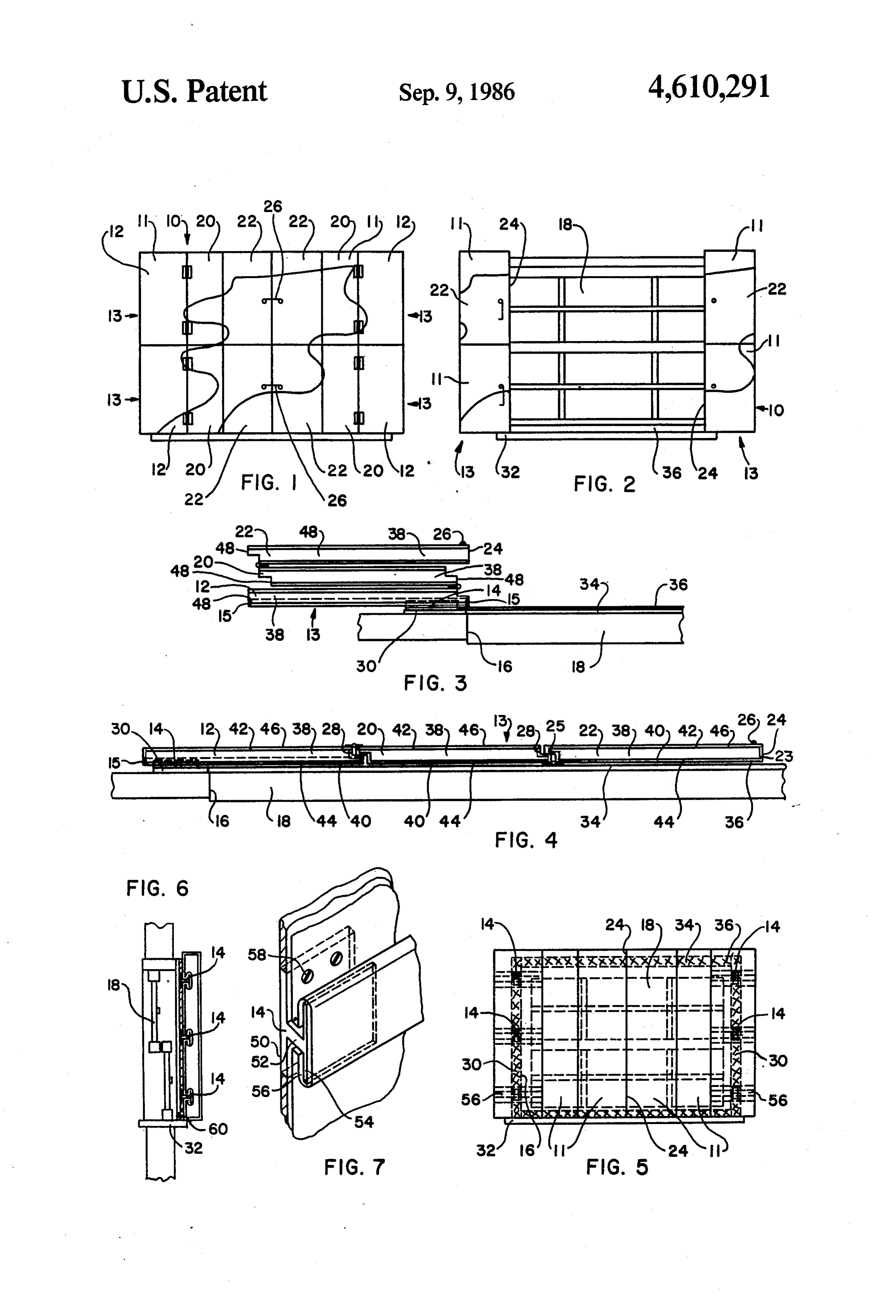
ticularly to decorative insulated shutter panels capable SUMMARY OF THE INVENTION of substantially exposing or completely covering a building opening by means which include at least in part 15 In keeping with one aspect of this invention, appara a sliding action of one or more of the shutter panels tus for insulating a window or other opening in a build relative to the opening. ing includes a plurality of rail means secured to the Recent energy shortages and increases in the cost of interior of the building adjacent at least one edge of the maintaining comfortable temperatures in buildings opening, and at least one insulated shutter panel slidably throughout the year have increased the demand for 20 engaged with the rail means. Several panels may be products which conserve energy, and products which assembled into a set of panels or opposing sets of panels collect and store energy. Insulation made of fiberglass installed on opposing sets of rail means, if desired. The or the like is commonly installed in building walls for shutter panel or panel assembly is capable of substan this purpose. Insulation is generally not installed in tially exposing or completely covering the opening due window or other openings, however, because it is not 25 at least in part to the sliding action of at least one of the transparent and permanently blocks the opening. As a shutter panels relative to the edge. The shutter panel or result, windows, doors and other openings are less en panel assembly may be filled with insulation or an en ergy efficient than the building walls, and generally ergy storage medium, such as a phase changing mate release a great deal of heat during cold months, and rial. The shutter panel or panel assembly may include absorb it in warm months. 30 decorative matter, if desired, and may also include a Storm windows and storm doors are often installed in switch or other means for activating an alarm if an windows and certain doors to increase energy effi intruder tampers with the shutter apparatus. ciency. Their usefulness is limited, however, because BRIEF DESCRIPTION OF THE DRAWINGS they are rarely sufficiently airtight to be effective, and are not as thermally efficient as fiberglass insulation or 35 The above mentioned and other features of this in the like. Other building openings, such as sliding doors, vention and the manner of obtaining them will become curved windows and non-rectangular windows are more apparent, and the invention itself will be best generally not provided with storm windows or the like. understood by reference to the following description of Their insulating efficiency may be improved by the use an embodiment of the invention taken in conjunction of multiple layers of glass, which is expensive, or by with the accompanying drawings, in which: securing plastic or the like to the outside of the opening, FIG. 1 is a front view of an assembly of the shutter which is generally unsightly. Thus, there is a need for panels of this invention showing the assembly in the practical, inexpensive apparatus for insulating building closed position;
openings which does not permanently cover the open FIG. 2 is a front view of the assembly of FIG. 1 ing, and is not unsightly. 45 shown in the open position;
Louvered shutters have been used on the inside of FIG. 3 is a top view of one set of the shutter panels of windows for many years. Such shutters are generally FIG. 1 in the open position;
specially manufactured to fit a particular window, and FIG. 4 is a top view of one set of the shutter panels of are hingedly mounted inside the window frame. The FIG. 1 in the closed position;
shutters are decorative and provide privacy, but are 50 FIG. 5 is an elevation view of the apparatus of this relatively expensive, and do not insulate the window. invention showing an assembly of shutter panels in the Thus, there is a need for decorative window shutters closed position;
which provide insulation and need not be specially FIG. 6 is a side view of the apparatus of FIG. 5; and manufactured, to decrease the cost. FIG. 7 is a cutaway perpsective view of a portion of Accordingly, an object of this invention is to provide 55 the apparatus of FIGS. 5 and 6 showing the rail means. new and improved apparatus for insulating windows or DESCRIPTION OF THE PREFERRED other openings in buildings which does not permanently EMBODIMENTS cover the openings.
Another object is to provide apparatus for insulating An assembly 10 of insulated shutter panels 11 may be windows or other openings in buildings which is rela 60 closed to completely cover a window 18 or other open tively inexpensive, and need not be specially manufac ing in a building, as in FIG. 1, or may be opened to tured for a particular sized opening. substantially expose the opening, as in FIG. 2. Panels 11 Yet another object is to provide apparatus for insulat conserve energy when in the closed position by retain ing windows or other openings in buildings which is ing heat in the building during cold weather, and keep decorative. ing the building cooler during warm weather. When the Still another object is to provide a new and improved panels 11 are open, light and solar heat may enter the insulating shutter panel which by itself or in a set of building, the window may be opened, and people inside panels is capable of substantially exposing or com the building may look out the window. The shutter 4 panels 11 may be used for windows, as in FIGS. 1 and thetically pleasing appearance when the shutter panels 2, or for doors or other openings, and may be used with are closed. The decorative matter may be a picture, a or without storm windows or storm doors. The shutter decorative pattern, a mirror surface or the like applied panels are also useful for openings such as sliding doors, to the panels in a variety of ways, including original irregularly-shaped windows and the like, where storm painting, adhesive paper or the like. A process for pho doors or storm windows are impractical. tographing original art work and lithographing it di The interior volume of insulated shutter panels 11 rectly onto metal sheets could be easily adapted to this may be filled with an energy storage medium, such as a application to provide decorative matter on the panels. phase changing substance, which also serves as an insu The panels could also be molded in the form of conven lator. Phase changing materials store solar heat energy 10 tional louvered shutters, if desired. The outside portions chemically, and are capable of absorbing and releasing of the panels could be molded to form a case and filled far more heat than previously known energy storage with insulation or an energy storage medium, or the media, such as water or rock. Suitable phase changing entire panel could be molded insulating plastic. materials are known to the art and are commonly re Rail means 14 is secured to the building structure ferred to as solar salts or eutectic salts. Solar energy 15 adjacent at least one edge 16 of the opening 18, as in absorbed during the day by one suitable phase changing FIGS. 3 and 4, and each assembly 10 includes at least material, for example, converts the phase change mate one outside shutter panel 12 which is slidably engaged rial from solid to liquid form. Energy stored in the with rail means 14 by grooves 56 (FIG. 7). At least one liquid form of the phase changing material may then be stop 15 (FIG. 3) is provided on each end of at least one released as heat during cooler evening or night hours as 20 groove 56 to adjust outside panels for proper opening the material is converted from the liquid to a solid state and closing and to prevent them from accidentally slid due to falling temperatures. ing off the rail means 14.
A hydrated salt which changes phase between a liq A second shutter panel 20 may be hingedly secured to uid and solid form at 55' F. has been developed by the outside panel 12 to swing away from the opening 18 University of Delaware's Institute of Energy Conver 25 when opened, and a third shutter panel 22 may be sion for use in air conditioning systems to store cool air hingedly secured to second panel 20 to fold compactly generated during times when off-peak energy rates are adjacent outside panel 12 when opened. Additional applicable. A variation of this system that would store panels could be used if desired.
solar heat generated during the day is being developed. When the shutter panel sets 13 are open, as in FIG. 3, Another thermal storage compound comprising cal 30 the shutter panels 11 lie compactly and neatly along the cium chloride hexahydrate has been developed by Dow edge 16 of the opening 18. In the closed position, the Chemical which changes phase between a liquid and outer edges 24 of opposing third panels 22 are adjacent solid form at 81 F. Any energy storage medium, such each other, and completely cover the opening 18, as in as a phase change compound which changes phase FIG. 5. The rail means 14 are always concealed from between about 50 F. and about 90°F. would be suitable 35 view. Opposing sets 13 may be secured by clasp means for use with the shutter panels of this invention. A nu 26 when closed, as seen in FIG. 1. Clasp means 26 may cleator may be added to the phase change material to be any known latch apparatus. Complementary notches prevent supercooling, and dyes may be added to the 28 may be provided along adjoining edges of adjacent energy storage medium to improve the aesthetic quali panels 11 to decrease further the flow of air between the ties of the shutter panels. 40 panels, which will further improve the ability of the Energy storage medium, such as phase change com assembly 10 to conserve energy. The notches 28 may pounds are preferably permanently sealed within the include plastic foam strips or some other material which interior volume of the shutter. The shutter itself, or an will further reduce air flow between the panels. interior liner, comprises a material which is non-reac The opening 18 generally includes trim pieces 30 tive with and impermeable to the phase change com 45 (FIG. 5) along the vertical edges of the opening, sill 32 pound, such as high density polyurethane or polyethyl along the bottom of the opening which extends away ene. The structural shutter itself may comprise molded from the window further than the trim pieces 30, and a high density polyurethane or polyethylene or the like, top trim piece 34, which is generally in the same plane with a phase change material sealed therein. If the struc as trim pieces 30. Shutter panel assembly 10 may be tural material and the phase change material are translu 50 installed above sill 32, and extends over and beyond cent, then when the shutters are closed during the day trim pieces 30. Assembly 10 extends over top piece 34, for collecting and storing heat energy, some light may and may extend beyond the top piece, if needed. Since still penetrate to the interior of the building. If a more the assembly 10 extends beyond trim pieces 30, and may decorative shutter panel is desired, a liner comprising extend beyond top trim piece 34, it need not be specially high density polyurethane or polyethylene or the like 55 manufactured for each window or other opening, and with phase change material sealed therein may be cov standard panel sizes may be used for many different ered with wood, plastic, metal or the like to provide a applications.
decorative appearance. The exterior side of the shutter A flexible magnetic strip 36, or some other suitable panel may be covered to provide a surface well suited to sealing device, such as foam or the like, may be pro collecting solar energy, such as a dull black surface, 60 vided around the opening 18, as in FIG. 5, if desired. An while the interior side of the shutter panel may be cov additional trim piece 60 may be provided along sill 32 ered to provide a decorative appearance. for installation of a magnetic strip along the lower edge The assembly 10 may include a single panel 11, a set of the assembly, for sealing purposes. The trim piece 60 13 of panels 11, or two opposing sets 13 of panels 11, also acts as a structural stop against lateral movements and may include several panels 11 or sets 13 of panels 11 65 of the panels toward the outside of the building. placed over each other vertically. Also, decorative Shutter panels 11 generally include a layer 38 of insu matter may be placed on the interior surface of the lating material such as polyurethane, polyisocyanurate, shutter panels 11, as seen in FIG. 1, to provide an aes fiberglass, polystyrene or the like, or layer 38 may com 5 prise an energy storage medium, such as a phase chang Installation of the shutter panels will be feasible for ing material. Face 40 of layer 38 is disposed toward the consumers and other relatively untrained personnel, opening 18, and opposing face 42 is disposed toward the without elaborate tools and the like. It is contemplated interior of the building. The layer 38 may be molded to that the rails 14 may be installed in trim 30 by screw form the panel, if desired, and the faces 40, 42 may form means 58 or other suitable means at predetermined in the outside surface of the panels. In the alternative, tervals. Magnetic-strip 36 may then be installed in ac molded or loose insulating material may be enclosed by cordance with the manufacturer's specifications. Trim additional pieces. If layer 38 comprises an energy stor piece 60 may be secured to sill 32 as a stop, and as a surface for installation of a magnetic strip 38. Shutter age medium such as a phase changing material, faces 40 10 panels and 42, along with edge portions 23 and 25, form a 11 may be pre-assembled, and installed by plac sealed casing comprising high density polyethylene or ing the outside panel grooves 56 on rails 14, and insert polyurethane or like material which is non-reactive ing stops 15 in the grooves after installation. The stops 15 may be adjusted so that the sets of panels open prop with and impermable to the energy storage medium. erly and do not buckle or overlap when closed. Stops 15 Shutter panels 11 comprising energy storage medium enclosed by an impermeable casing may form a struc 15 may netic be a barbed cap, a screw device, or the like. Mag sensors or switches of various kinds may be at tural shutter unit which is translucent and which allows some light to penetrate to the interior of the building. iftachedan to the opening or assembly to activate an alarm intruder tampers with the panels when closed.
Alternatively, the sealed casing may be covered on any In use, the panels may be closed by folding second of its surfaces with a layer of plastic, metal, or the like, panels 20 and third panels 22 over opening 18, and such as covers 44, 46 and 48, described below, to pro sliding opposing sets of panels together. Magnetic strip vide a more decorative shutter panel, or to provide the 36 will preferably be strong enough to secure the panels shutter panel with greater insulating or energy collect and seal them, but will not interfere with the ease of ing properties. A shutter panel having a layer 38 com sliding the panels. The panels may also be closed by prising energy storage medium, particularly phase 25 sliding outside panels 12 toward each other to stops 15 changing material, provides a shutter panel having sig and folding panels 20, 22 over opening 18. Opposing nificantly greater insulating properties than a shutter sets 13 may be secured together by clasp means 26. To panel of hollow or solid wood, metal or plastic con open the shutters, clasp means 26 must be released, struction. Layer 38 comprising a phase changing mate second shutters 20 and third shutters 22 may be pulled rial functions as an effective insulator, particularly 30 away from the opening 18 and folded over outside shut when the phase changing material is in the solid phase. ter panels 12, and panels 12 may be moved to the edges Exterior cover 44 may be secured adjacent to the 16 of opening 18.
opening face 40, and interior cover 46 may be secured The advantages of this invention are now self-appar adjacent to interior face 42. Covers 44, 46 may be se ent. The assembly of insulated shutter panels conserves cured by side covers 48, or any other suitable means. 35 energy when closed over an opening in a building, and, While the covers 44, 46 and 48 may comprise any suit when shutter panels enclose an energy storage medium, able material, it is contemplated that exterior cover 44 the shutter panels collect and store heatenergy, without may be thin sheet metal which may be magnetically permanently covering the opening. In addition, the attracted to magnetic strip 36, interior cover 46 may be assembly is aesthetically pleasing when the shutters are metal or other material capable of carrying decorative 40 closed. The shutters may easily be installed by consum matter, and side covers 48 may be plastic, which will ers, and a standard size shutter may be adopted to fit conserve energy, or metal. When layer 38 comprises an many sized openings, without special fabrication. energy storage medium, exterior cover 44 preferably While in the foregoing specification this invention has has a dull, dark colored surface facing the exterior of been described in relation to certain preferred embodi the building to provide enhanced solar energy collec 45 ments thereof, and many details have been set forth for tion capacity. In outside panels 12, grooves 56 may be purpose of illustration, it will be apparent to those formed in the exterior cover 44 by many known means. skilled in the art that the invention is susceptible to Rail means 14 provides support for each set 13 of additional embodiments and that certain of the details shutter panels 11. It is contemplated that at least two described herein can be varied considerably without rails 14 will be required for each set 13. Rails 14 may be 50 departing from the basic principles of the invention. secured to the trim 30 as in FIGS. 3 and 4, or may be I claim:
secured adjacent the edge of the opening 18. If rails 14 1. Apparatus for covering a window or other opening are secured to the trim 30, it may be necessary to level in a building comprising:
the rails 14 with shims or other suitable means. a plurality of horizontal rail means secured to the Rails 14 include a first leg 50 secured to the trim 30, 55 interior of said building adjacent to and extending a second leg 52 extending outwardly toward the inte only outwardly from at least one generally vertical rior of the building substantially perpendicular to leg edge of said opening in a plane parallel to said 50, and a third leg 54 extending from the outer end of opening;
the second leg 52 substantially perpendicular to leg 52. at least one shutter panel slidably engaged with said Grooves 56 of outside panel 12 slide on rails 14. 60 rail means, said rail means extending horizontally a The dimensions of the elements of this invention may distance substantially less than the width of said vary according to the application. It is contemplated slidably engaged shutter panel to provide conceal that layer 38, comprising insulating material or an en ment of said rail means when said slidably engaged ergy storage medium, may be about 1 to 4 inches thick, shutter panel is in extreme slidable position in each and the shutter panels 11 may be about 12 inches wide 65 direction and capable of substantially exposing and and up to about 36 inches in length. The depth of the substantially covering said opening due to the slid rails 14 may be between and 2 inches from the trim ing action of said slidable shutter panel relative to pieces 30. said vertical edge;
Page 6scan →
energy storage medium within the interior volume of at least one insulated shutter panel slidably engaged said at least one shutter panel capable of collecting, with said rail means, said rail means extending storing and releasing solar energy. horizontally a distance substantially less than the 2. The apparatus of claim 1 comprising means for width of said slidably engaged shutter panel to sealing said shutter panel to said building around the 5 provide concealment of said rail means when said edges of said opening. slidably engaged shutter panel is in extreme slid 3. The apparatus of claim 2 wherein said sealing able position in each direction; and means comprises a magnetic strip around the edges of a second insulated shutter panel hingedly secured to said opening. the vertical edge of said slidable panel adjacent said 4. The apparatus of claim 1 wherein said rail means O opening in open position, and said hingable panel in comprises a plurality of rails secured to the interior of combination with said slidable panel being capable said building, said rails comprising a first leg secured to of substantially exposing and completely covering said building, a second leg extending outwardly sub said opening due at least in part to the sliding action stantially perpendicular to said first leg, and a third leg 15 of said slidable shutter panel relative to said verti cal edge;
extending from the outer end of said second leg substan energy storage medium within the interior volume of tially perpendicular to said second leg, said slidable said shutter panels capable of collecting, storing shutter panels comprising a plurality of grooves for said and releasing solar energy. rails, and a plurality of stops in at least one of said 6. The apparatus of claim 5 wherein said slidable grooves to prevent said shutter panels from sliding off 20 panel and said second panel comprise complementary said rails after installation. notches in adjoining edges.
5. Apparatus for covering a window or other opening 7. The apparatus of claim 6 wherein said notched in a building comprising: edges comprise insulating material secured along said a plurality of horizontal rail means secured to the edges for sealing said adjoining edges.
interior of said building adjacent to and extending 25 8. The apparatus of claim 5 comprising a third panel only outwardly from at least one generally vertical hingedly secured to said second panel to substantially edge of said opening in a plane parallel to said expose and completely cover said opening.
opening; as k
Provenance
- Collection
- Patents citing this work
- Pages
- 6
- Method
- pdftotext (the PDF's own text layer) + pdftoppm 300dpi page scans
- Patent office record
- patents.google.com →
- Source
- Google Patents citing-documents table
- Assignee
- Carroll Frank E
- Published
- 1986-09-09
- Transcribed from
- patentimages.storage.googleapis.com →