

patent · US4612913A
Solar energy collector array
23 September 1986
Text
Page 1bibliographic recordscan →
United States Patent (19)
Mori
54 SOLAR ENERGY COLLECTOR ARRAY
Inventor: Hiroki Mori, Tokorozawa, Japan 73 Assignee: Ilios Corporation of Japan, Tokyo,
Japan
30 Foreign Application Priority Data
Apr. 3, 1984 JP Japan .................................. 59-66133 51l Int. Cl. ................................................. F24J 2/10 52 U.S. Cl. .................................... 126/438: 126/424;
3,797,915 3/1974 Land et al. ...................... 350/613 X
4,257,401 3/1981 Daniels ........................... 26/440 X
4,344,673 8/1982 Holdridge ........................... 350/614
Primary Examiner-Larry Jones
Attorney, Agent, or Firm-Costas, Montgomery &
Dorman
A concentrating reflector adapted to focus light on a target spaced a predetermined distance from the reflec tor comprising a lens, a linear echelon element closely positioned to said lens and a mirror surface, the lens, the echelon element and the mirror surface being so ar ranged that light entering the lens and the echelon ele ment is refracted and reflected back through the lens to said target for a given angle of incidence of light rays thereon.
11 Claims, 11 Drawing Figures
Drawings
Page 2drawing sheetscan →
Page 3drawing sheetscan →
Page 4drawing sheetscan →
Page 5scan →
An object of this invention is to provide a new and
SOLAR ENERGY COLLECTOR ARRAY improved solar concentrating and reflecting system of the type described.
FIELD OF THE INVENTION Another object of this invention is to provide a new This invention relates to solar energy collection sys and improved solar energy concentrating and reflecting tems, and more particularly, relates to a passive non system of the type described which is quite compact. tracking system which provides the benefits of a track A further object of this invention is to provide a new ing system using new and improved concentrating and and improved solar energy and concentrating system of the type described which is low cost in manufacture and reflecting modules that will focus the sun's rays on a 10 assembly.
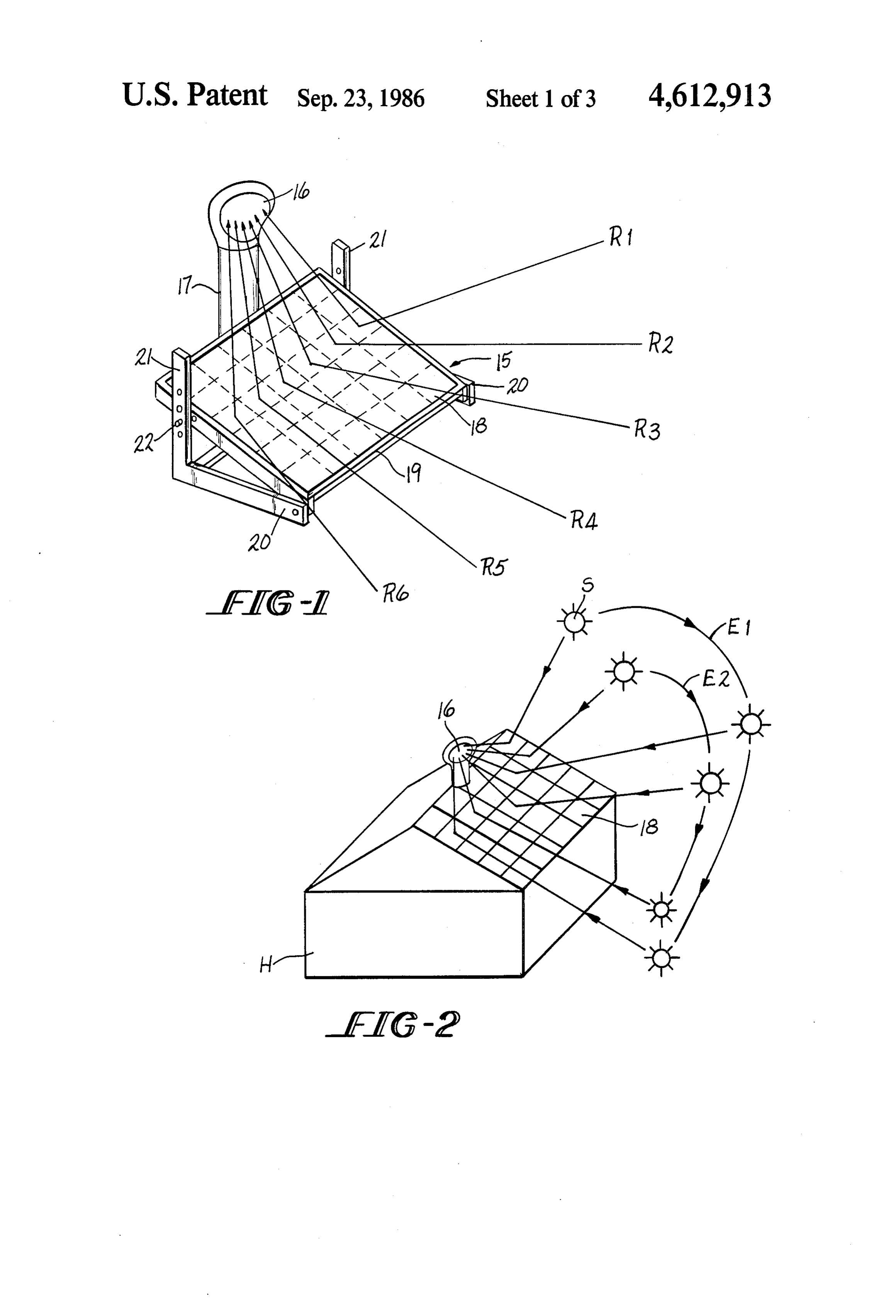
collecting device. The features of the invention which are believed to be BACKGROUND OF THE INVENTION novel are particularly pointed out and distinctly Solar energy systems have previously been proposed The claimed in the concluding portion of the specification. invention, however, together with further objects which will reflect the rays of the sun to a central collec 15 and advantages thereof, may best be appreciated by tor. Such systems generally comprise a multiplicity of reference to the following reflectors which are mechanically, electromechanically conjunction with the drawings. detailed description taken in or electronically controlled to follow the movement of the sun and reflect the sun's rays to an absorbing or BRIEF DESCRIPTION OF THE DRAWINGS collecting device. In some cases, the positioning of the 20 FIG. 1 is a perspective view of a solar energy collec reflectors are under the supervision of a program which tor system embodying the invention with reflective takes into account the latitude of the installation and the modules on a pivotally adjustable support; elevation and azimuth of the sun for particular seasons, FIG. 2 is a perspective view of a solar energy collec or even days of the year. Such tracking systems require tor system embodying the invention mounted to the very complex tracking equipment and/or program 25 roof of a structure;
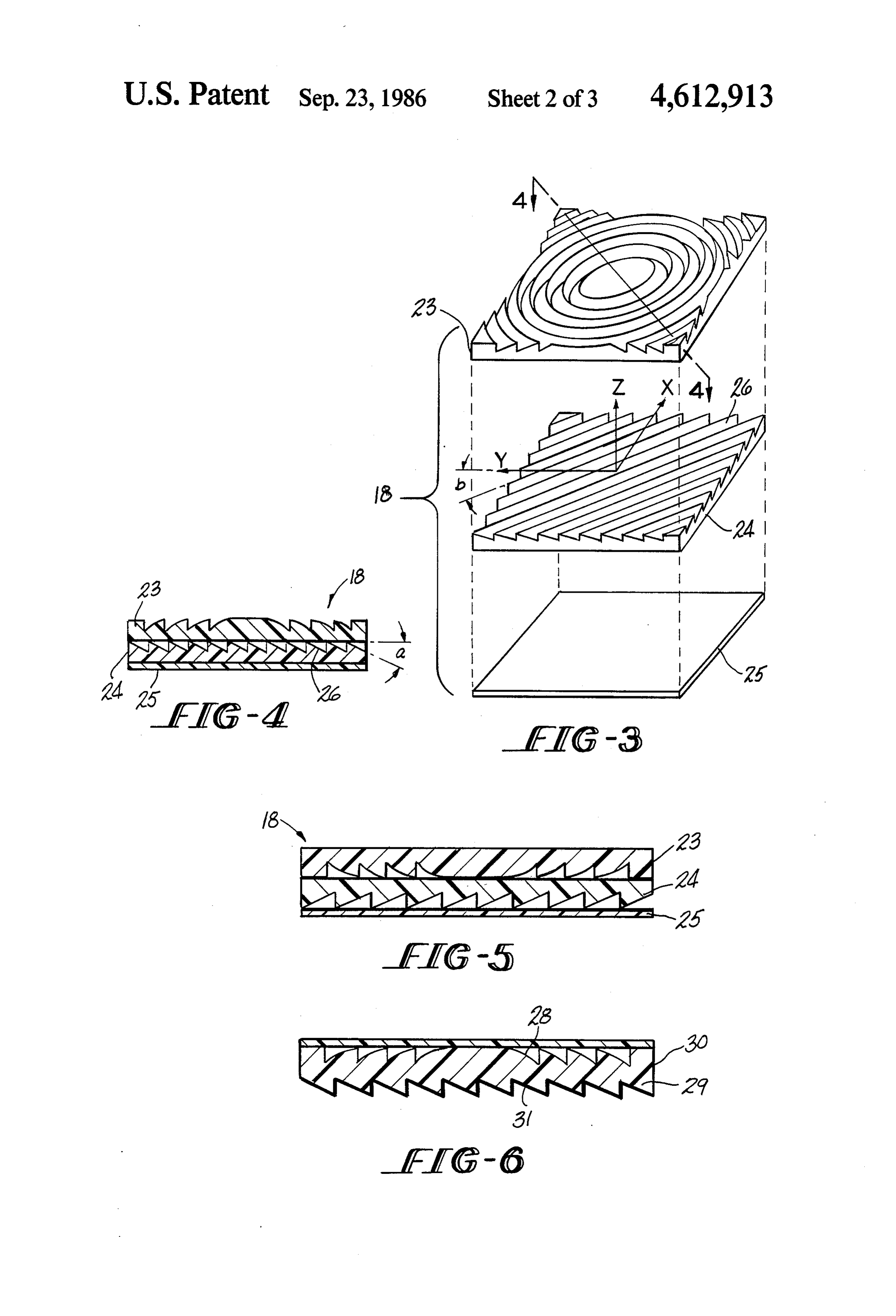
ming, and as a result, are quite expensive. At least one FIG.3 is an exploded view in perspective of a reflect system has been proposed which utilizes a rotating ing module embodying the invention;
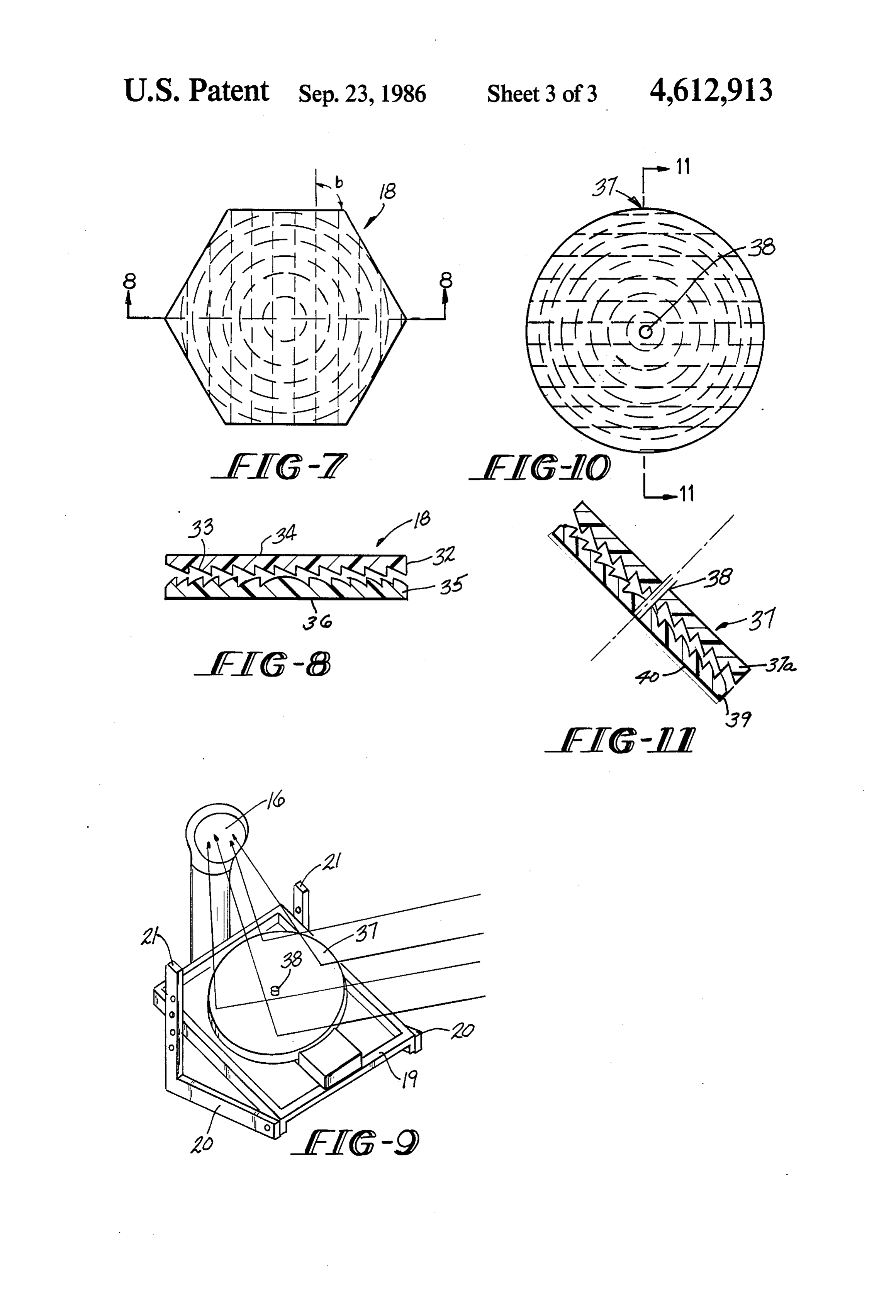
prism to direct the sun's rays to a mirror which reflects FIG. 4 is a view of the reflector module of FIG. 3 through a lens to a target. A system of this type is dis with the elements thereof in stacked relation; closed in U.S. Pat. No. 4,382,434. FIGS. 5 and 6 are views similar to FIG. 4 showing The present invention provides a solar energy collec alternate embodiments of the invention; tion system which utilizes a plurality of passive lens FIG. 7 is a plan view of a reflecting module embody modules which act to focus and transmit the sun's rays ing the invention which is hexagonol in shape; to a collection point or area and essentially provide the FIG. 8 is a section seen in the plane of lines 8-8 of equivalent of a tracking system which requires no mov 35 FIG. 7;
ing reflectors. FIG. 9 is a perspective view of an alternate embodi ment of the invention in which a reflective module
SUMMARY OF THE INVENTION embodying the invention relates to follow the azimuth Briefly stated, the invention in one form thereof com 40 of the sun;
prises a solar energy system which utilizes a plurality of FIG.FIG. 10 is a plan view of the reflective module of lens-reflector modules to focus and reflect the sun's rays 9; and on a collecting or absorbing target. Different groups of FIG. FIG. 11 is a view seen in the plane of lines 11-11 of modules have different angles between the lens and the reflector so that at least one or one group of modules 45 DETAILED DESCRIPTION OF PREFERRED always reflects the sun's rays to the target EMBODIMENTS OF THE INVENTION The modules are preferably constructed utilizing a Referring now to FIG. 1, there is exemplified an fresnel lens having a predetermined focal length to array 15 of lens-reflector focus the sun's rays at the target. The reflectors are as herein described so that modules which are arranged at least some of the condens preferably echelon refractors with a reflective coating 50 ing reflectors concentrate and reflect the sun's rays on a on a rear planar surface. The surfaces of the echelon collecting device 16. Collecting device 16 is mounted elements are oriented with respect to the coordinate on a support member 17 which may axes of the associated focusing lens such that at a given heat responsive device as hereinafter include a light or azimuth of the sun, one or more or a group of the mod 15 comprises individual condensing and reflectingArray described.
mod ules will reflect and focus the sun's rays on the target. 55 ules 18. The modules 18 are arranged in columns and The modules may take several forms. In one embodi rows (thirty-six as shown) on a carrier 19 which is piv ment, the lens, echelon element, and a mirror are three oted to support members 20 at the lower end thereof. separate elements. In other embodiments, the echelon Carrier 19 is supported by support members 20 and 21 element may have a reflective coating on the planar as by means of pins 22 to vary the angle of inclination of surface. In still another embodiment, the fresnel lens is 60 carrier 19. The angle of inclination of carrier 19 may be formed on one side of a transparent lens, a linear eche seasonably adjustable. In FIG. 1, rays of the sun refer lon lens is defined on the rear surface, and the echelon enced as R1-R6 are shown impinging on the six col prism surfaces are coated with a reflective coating. umns of modules at different times of the day. As the The modules are very compact and the lens and eche azimuth of the sun changes during the day, different lon element are in very close relation or even stacked 65 columns of the modules will focus and reflect the sun's relation. Where the lens and the echelon element are on rays to collecting device 16. The support structure is separate members, the planar surfaces thereof are essen only exemplary. In actual practice, motorized means tially parallel. would be used to adjust the angle of support 19.
Page 6scan →
FIG. 2 shows an array of modules 18 mounted to the FIG. 5 shows a module 8 where a lens 23 has been roof of a structure H and exemplifies the sun S at eleva inverted in order to protect the fresnel surface. tions E1 and E2. Here the modules 18 are set for both FIG. 6 shows a module 18 where a fresnel lens 28 and elevation and azimuth of the sun. As the sun travels at echelon prisms 29 are defined on a single transparent elevation E1, some of the modules will reflect to col 5 member 30. The echelon surfaces are coated with a lecting device 16, while at elevation E2, other modules reflective coating 31. A transparent cover plate 28 is will reflect to collecting device 16. provided to protect the fresnel surface 28. The collector 16 may take many forms, it may be a FIGS. 7 and 8 illustrate a further embodiment of the selective surface within the top of support 17, it may be invention where a module 18 is hexagonal in shape. The coils with heat absorbing surfaces adapted to have a upper element is a linear echelon refractor 32 having liquid to be heated passed therethrough, it may be prisms 33 and a coating 34 on the planar surface to photo-voltair cells to generate electricity or any other minimize reflection of entering light. A fresnel lens 35 suitable device which will connect light to another form faces the prisms 33 and has a reflective coating 36 on its of energy. In some cases, the optical fibers may be 15 rear planar surface.
curved to direct the light energy downwardly in hollow The hexagonal shape provides great versatility in that support member to a utilization or absorbing device. a plurality of lens 35 may be made to different focal The support 17 may contain a thermomotor driving a lengths and a plurality of echelon elements having dif generator where the thermomotor is driven by the ex ferent prism angles a, then can be selected and paired pansion of heated gases. appropriately to concentrate all entering light onto a Reference is now made to FIG. 3 which is an ex 20 collector. If three types of echelon elements are made ploded view of one of the modules 18. Each module 18 with angles of orientation b of 0, 10, and 20, then by comprises a refracting lens 23 shown as a fresnel lens, a rotating the member 32 in sixty degree intervals, it is linear echelon refractor 24, and a mirror 25. FIG. 4 possible to shift at will the direction of reflected light shows the lens 23, the echelon refractor 24, and the 25 output in ten degree increments. This provides a mod mirror 25 stacked into a module. As shown, the prisms ule which is well suited to mass production and easy 26 of the echelon refractor are at an angle a. As shown assembly of parts.
in FIG. 3, X, Y and Z axes are defined, and the echelon FIG. 9 exemplifies a module embodying the inven refractor 24 defines an angle of orientation b with the Y tion which is suitable for active tracking. The module axis. The X and Y axes are referred to as the coordinate 30 37 is rotatably mounted about an axis 38 on support 19, axis of the lens while axis Z is the optical axis. This and is edge driven by a motor (not shown) in a housing angleb may vary from module to module to determine 39 on support 19.
the angle of reflection. The modules 18 are constructed The position of the module 37 is synchronized with with a focal length of the lens 23 substantially equal to the azimuth of the sun and the support 19 is adjusted for the distance of the lens to the collector 16 considering 35 the seasonal elevation of the sun. that light passes through the lens twice. Thus, light FIG. 10 shows a plan view of the module 37 of FIG. passing through the lens will be refracted the prisms 26 9.
of echelon refractor 24, then reflected by mirror 25 FIG. 11 is a view seen in the plane of lines 11-11 of back through echelon reflector 24 and lens 23 to collec FIG. O.
tor 16. In the arrangement shown in FIG. 1, the support 40 The module 37 comprises an upper linear echelon 19 is set at an angle in accordance with the latitude of refractor 37a and a lower fresnel lens 39 having a re installation and the season. Throughout the daylight flecting coating 40 on the rear surface thereof. Light hours of a given season, some of the condenser reflector will enter the planar surface of element 37a, refract on modules will be concentrated on collector 6. Prefera the prism surfaces, enter lens 39 and refract, reflect from bly, the angle of inclination b of the echelon surfaces is 45 mirror surface 40, refract as it leaves lens 39, refract set so that at least one column of modules 18 reflect upon entering element 37a, and again refract as it leaves simultaneously on collector 16. It will be noted that element 37a. As shown in FIG. 9, light rays L1-L4 echelon refractor 24 may be placed in four different strike module 37 and are focused and reflected to col orientations with respect to lens 23. This will give four lector 16. As the sun moves in azimuth module 37 is possible angles of reflection to the sun's rays concen 50 rotated accordingly so that the rays L1-LA are focused trated by lens 23. Additionally, the echelon elements on and reflected to collector 16. may be formed with several different angles b, as here While the component parts of the modules 18 have inafter described. been shown in schematic form, it will be understood With the light passing through the lens twice, the that the elements may be held together in a peripheral optical power of the lens need not be great optical. This 55 housing including any spacing members necessary so results in a less expensive lens since the grooves defining that each module in its housing may be appropriately the lens need not be as deep and the average angle of orientated with respect to other modules. each facet is more shallow. It may thus be seen that the objects of the invention While the modules are shown in FIGS. 3 and 4 as set forth, as well as those made apparent from the fore comprising three individual elements, it is to be under 60 going description, are efficiently attained. While pre stood that a mirror surface may be formed on the planar ferred embodiments of the invention have been set forth underside of echelon refractor 24. Alternatively, the for purposes of disclosure, however, modifications to prisms 26 may be oriented to the rear and coated with a the disclosed embodiments of the invention, as well as reflective material. Additionally, it is preferable to have other embodiments thereof, may occur to those skilled the fresnel lens 23 inverted in position, as shown in FIG. 65 in the art. Accordingly, the appended claims are in 5, to protect the fresnel lens surfaces from dirt, dust and tended to cover all embodiments of the invention and - the atmosphere generally. Alternately, a transparent modifications to the disclosed embodiments which do sheet or plate may be placed over lens 23. not depart from the spirit and scope of the invention.
Page 7scan →
Having thus described the invention, what is claimed 5. The concentrating reflector of claim 1 where the is: focal length of said lens is substantially twice the dis 1. A concentrating solar reflector adapted to focus tance between said lens and said target. light on a target positioned and spaced a predetermined 6. The concentrating reflector of claim 1 where said distance from said reflector comprising a lens having reflector is circular in shape and is rotatably driven to follow the azimuth of the sun.
optical power and a predetermined equivalent focal 7. The concentrating reflector of claim 6 where the length, a linear echelon element having parallel prisms planar surface of said echelon element is outward, said defined thereon closely positioned to said lens, and a fresnel surface of said lens and said echelon surfaces are mirror surface, said lens, said echelon element and said 10 facing and the mirror is defined by a reflective coating mirror surface having an optical axis and being so ar on8.theInplanar surface of said lens. ranged that light entering said lens and said echelon collectinga solar energy collecting system including a target, a plurality of passive concentrating element is refracted and reflected back through said lens reflector modules having an optical axis and adapted to to said target for a given angle of incidence of light rays 15 reflect the sun's rays to said target, each of said module thereon, said echelon element being angularly posi comprising a fresnel lens having optical power and a tioned with respect to the optical axis such that said predetermined equivalent focal length, a linear echelon prisms refract and said mirror surface reflects to said element having parallel prisms and a mirror surface, target for a predetermined angle of incidence of solar 20 said lens and said echelon element being so angularly rays on said solar reflector, said target being positioned positioned prisms with respect to the optical axis that said refract solar rays passing through said lens and above said reflector.
said mirror reflects solar rays back through said lens to 2. The concentrating reflector of claim 1 formed on a said target for a predetermined angle of incidence of single transparent member, the lens being fresnel and solar rays on said reflector module.
formed on the upper surface of said member and the 25 9. The system of claim 8 where said modules are echelon surfaces formed on the lower surface, said mir positioned in a planar array, the angle between the ror being provided by a reflective coating on the eche edges of said echelon surfaces and the coordinate axes lon surfaces. of said lens varies depend upon the position of a module in said array.
3. The concentrating reflector of claim 1 wherein said 30 10. The system of claim 8 where said module is echelon element is above said lens with the planar sur formed on a single transparent member, the lens being face thereof exposed, said lens is a fresnel lens having a fresnel and formed on the upper surface of said member planar rear surface coated with a reflective material to and the echelon surfaces the lower surfaces, said mirror define said mirror. being provided by a reflective coating on the echelon 4. The concentrating reflector of claim 1 where said 35 surfaces.
lens is a fresnel lens having its planar surface outward, 11. The system of claim 8 where the echelon element and said echelon element having a planar surface adja thereof of each module is above the lens with the planar surface cent said lens, the echelon surfaces of said element being nar rearexposed, said lens is a fresnel lens having a pla surface coated with a reflective material to coated with a reflective material to define said mirror, 40 define said mirror.
said planar surfaces being essentially parallel. sk k ak 2k 2k
Provenance
- Collection
- Patents citing this work
- Pages
- 7
- Method
- pdftotext (the PDF's own text layer) + pdftoppm 300dpi page scans
- Patent office record
- patents.google.com →
- Source
- Google Patents citing-documents table
- Assignee
- Ilios Corporation of Japan
- Published
- 1986-09-23
- Transcribed from
- patentimages.storage.googleapis.com →