

patent · US4655196A
Through the wall solar cooker
7 April 1987
Text
Page 1bibliographic recordscan →
United States Patent (19)
Kerr
(54) THROUGH THE WALL SOLAR COOKER
76 Inventor: Barbara P. Kerr, P.O. Box 576,
Taylor, Ariz. 85939
Int. Cl'................................................. F24J 2/02 52 U.S. C. ....... p ... 126/451; 126/439;
3,841,302 10/1974 Fallbel .................................. 126/439 4,018,212 4/1977 Hein et al............................ 126/45 4,077,391 3/1978 Way, Jr. .............................. 26/451 4,141,337 2/1979 Bergen ................................ 26/429
4,149,520 4/1979 Arent .................................. 126/451 4,203,427 5/1980 Way, Jr... ... 126/451 4,212,288 7/1980 Lipinski ... ... 126/428 4,236,508 12/1980 Kerr .... ... 126/451 4,274,397 6/1981 Hill ...... ... 126/45 4,284,067 8/1981 Kilar ... ... 126/438 4,559,925 12/1985 Snow .................... ............... 126/431 Primary Examiner-James C. Yeung
Attorney, Agent, or Firm-Warren F. B. Lindsley
A solar oven or cooker for permanent installation as a kitchen appliance with provision made for collection of solar radiation throughout the daylight hours. Reflec tive panels are provided for coping with changes in the position of the sun, and with the different requirements of various cooking operations which reflective panels may be fixedly arranged or adjustably positioned by the operator.
14 Claims, 13 Drawing Figures
Drawings
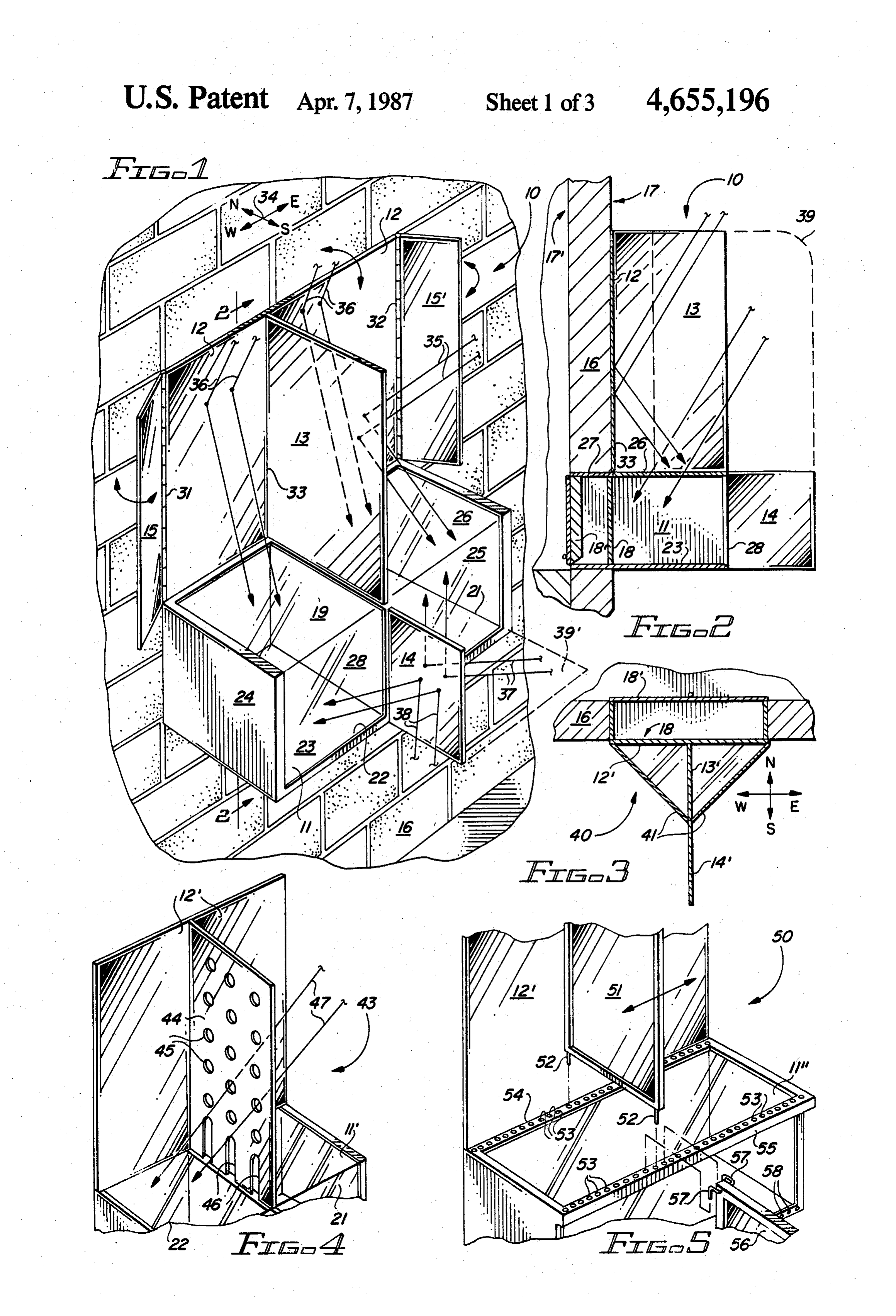
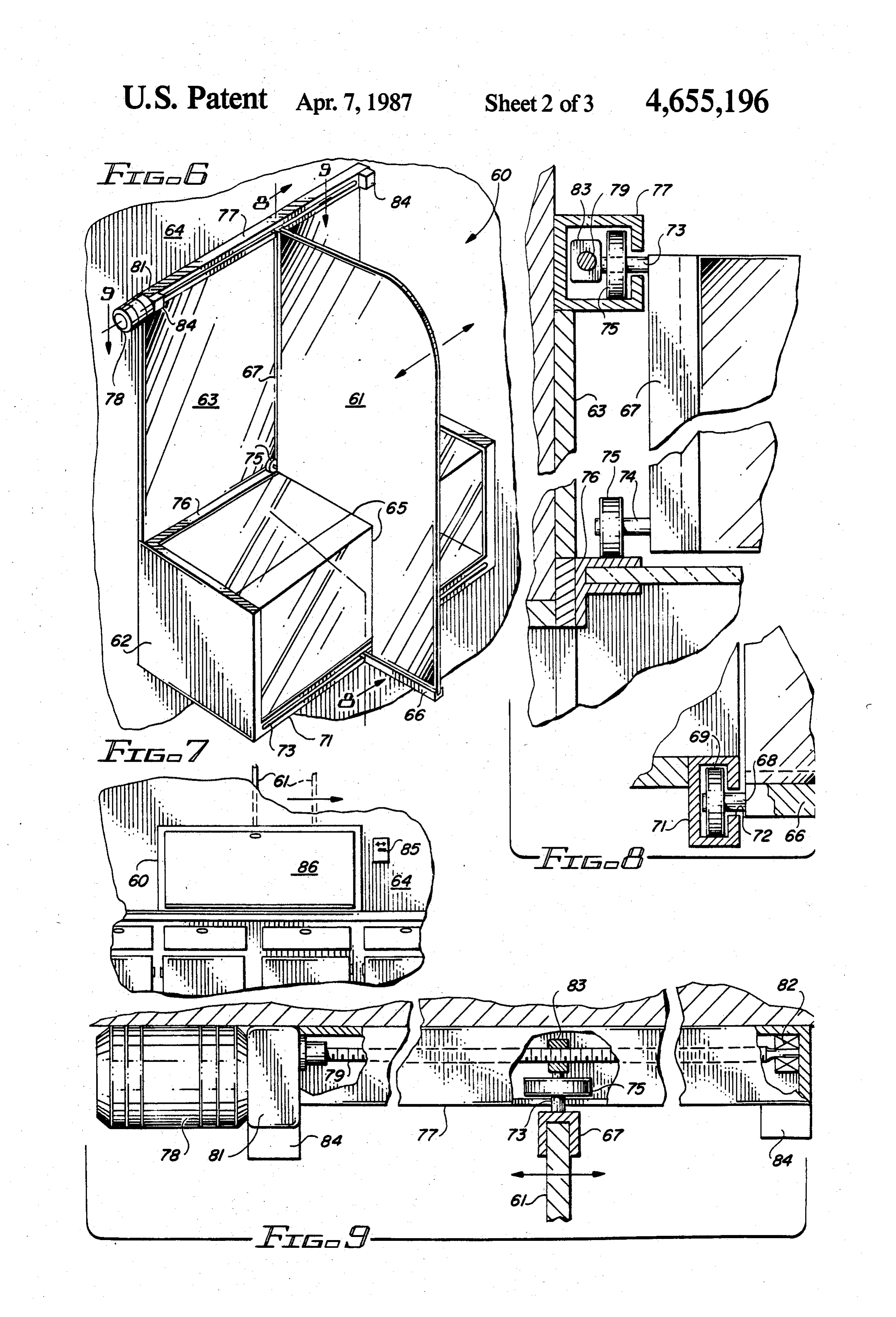
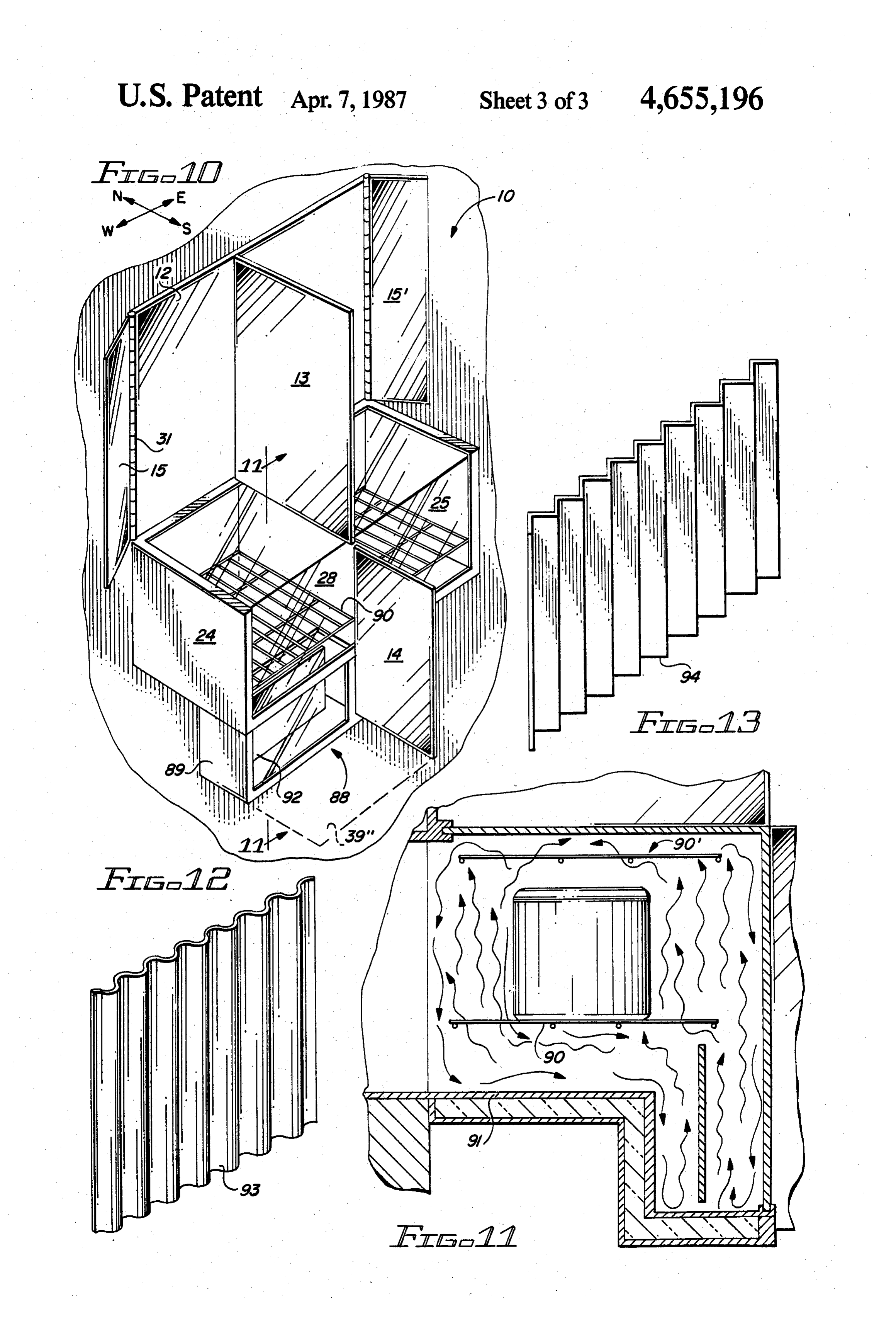
FIG. 1 is a partial perspective view of a through the
FIG. 8 is a segmented cross-sectional view of FIG. 6 taken along the line 8-8;
Page 2drawing sheetscan →
Page 3drawing sheetscan →
Page 4drawing sheetscan →
Page 5scan →
employing means for capturing solar radiation that is
THROUGH THE WALL SOLAR COOKER adjustable for accommodating the constantly changing orientation of the sun throughout the day and the sea
BACKGROUND OF THE INVENTION sons of the year, and which oven may be loaded and The recently aroused public interestin fossil fuels, the 5 unloaded from inside and outside of the building. over-consumption of firewood, the burning of waste A still further object of the invention is to provide matter and the rise in electrical energy costs, have such a solar cooker that may be economically built and prompted an increased interest in solar energy. The assembled for use in new or existing buildings. primary focus of such interest and the technical endeav 10 Further objects and advantages of the invention will ors that have followed have been primarily in the area become apparent as the following description proceeds, of home heating, solar water heaters and solar cookers. and the features of novelty which characterize the in Solar cookers have been limited to portable types that vention will be pointed out with particularity in the are periodically oriented for continuous exposure to the claims annexed to and forming a part of this specifica Sl. tion.
The development of an indoor solar oven or cooker 5 BRIEF DESCRIPTION OF THE DRAWINGS as an appliance that supplements the ordinary gas and electric range had to contend with the difficulty of The present invention may be more readily described capturing the solar rays of the sun, and making them with reference to the accompanying drawings, in available to the solar cooker on a continuous basis which:
throughout the daylight hours. 20
FIG. 1 is a partial perspective view of a through the
The present invention employs a new approach for wall solar cooker embodying the invention and show dealing with these problems, providing a cooker or ing that portion of the cooker projecting through the oven that may be installed to extend through an outside kitchen wall;
wall of a kitchen with the device operated from inside FIG. 2 is a cross-sectional view of FIG. 1 taken along
DESCRIPTION OF THE PRIOR ART FIG. 3 is a horizontal cross-sectional view of a fur Portable solar cookers are known and described in ther embodiment of the invention; U.S. Pat. Nos. 4,203,427; 4,077,391 and by 4,236,508. FIG. 4 is a partial perspective view showing a perfo U.S. Pat. Nos. 4,212,288 and 4,149,520 disclose means 30 rated variation of a reflective panel that may be incor for transmitting solar energy through a window to heat porated in the oven of FIGS. 1 and 2; FIG. 5 is a partial perspective view illustrating how the living space of a building.
the position of a reflective panel may be altered to ac
U.S. Pat. No. 4,018,212 discloses a housing perma commodate nently stationed inside a residential structure with the various positions of the sun or to achieve housing incorporating a liquid heat transfer medium, a 35 different levels of heating inside the cooking structure; radiation receiver in heat exchange contact with the FIG. 6 is a perspective view showing another em medium and a heating and cooking surface in heat ex bodiment of the invention in which a reflective panel is change relationship with the medium. A radiation pipe supported by rollers which permit the panel to be extends through the exterior wall of the building to moved to different positions;
deliver a concentrated beam of solar radiation to the FIG. 7 is a perspective view showing that portion of radiation receiver. the cooker of FIG. 6 as seen from inside the kitchen;
Summary of the invention
FIG. 8 is a segmented cross-sectional view of FIG. 6 taken along the line 8-8;
In accordance with the invention claimed, a new and FIG. 9 is a segmented partially cross-sectional view improved through the wall solar cooker or oven is 45 of FIG. 6 taken along line 9-9;
provided for use as a permanently installed kitchen FIG. 10 is a perspective view similar to FIG. 1 of a appliance having reflective means mounted outside of through the wall solar cooker employing a solar heat the building for capturing solar radiation throughout concentrator mounted below the oven for directing the daylight hours and for introducing it into the oven heat into the base of the oven;
or cooker. 50 FIG. 11 is a cross-sectional view of FIG. 10 taken It is, therefore, one object of this invention to provide along the line 11-11;
a new and improved solar oven or cooking appliance. FIG. 12 is a perspective view of a corrugated solar Another object of this invention is to provide a new ray absorbing plate for use in the concentrator shown in and improved through the wall cooker employing re FIGS. 10 and 11; and flectors arranged to passively reflect sufficient sunlight 55 FIG. 13 is a perspective view of a modification of the for cooking purposes regardless of the position of the solar ray absorbing plate shown in FIG. 12. sun due to the time of day or season of the year. DESCRIPTION OF THE PREFERRED A further object of this invention is to provide a new EMBODIMENT and improved through the wall solar cooker which may employ user adjustments for varying the amount of 60 Referring more particularly to the drawings by char solar radiation that is introduced into the oven, thereby acters of reference, FIGS. 1 and 2 disclose a solar oven adjusting the operating temperature of the oven. or cooker 10 defining an oven and cooking compart A still further object of this invention is to provide a ment 11 and reflective panels 12, 13, 14, 15 and 15'. new and improved through the wall solar cooker that Cooking compartment 11 in the form of a rectangular may be loaded, operated, adjusted and unloaded from 65 box projects outwardly from the inside of a kitchen inside the kitchen. through an outside wall 16 of a dwelling where it is A still further object of this invention is to provide a exposed to the atmosphere. The opening of the cooking solar cooker extending through the wall of a building compartment into the kitchen, which is herein referred 6 to as the front of the cooker, may be flush with the sun pass directly through glass plates 26 and 28 into outside surface 17 of wall 16 and closed by a thermally both cells 21 and 22. As noon approaches, the sun's rays insulated door 18 as shown in FIG. 2. A further door 18' 36 also strike panel 12 at both sides of panel 13 and are arranged flush with the inside surface 17" of wall 16 may reflected downwardly through plate 26 into both cells be provided, if so desired. A wall 19 at the center of 5 21 and 22. As noon approaches, rays incident upon compartment 11 divides compartment 11 into left and panel 15 also may be reflected downwardly into cell 22 right cooking ovens or cells, 21 and 22, respectively, as when panel 15 is pivoted slightly forward as shown in viewed from inside of the kitchen. Bottom and end FIG. 1. Similarly, as the sun passes its high noon posi walls 23, 24 and 25, respectively, of compartment 11, tion, rays incident upon panel 15' may be reflected into are thermally insulated and preferably surfaced inside O cell 21. Panel 14 makes its maximum contribution in compartment 11 with reflective material for directing early morning when incident rays 37 are reflected from the light on to the cooking vessels where it is converted its right-hand face to pass through rear wall 28 into cell to heat in the vessel, directly in contact with the food 21, and in late afternoon when the rays 38 of the setting adjacent its inner surface. If desired, heat absorbing sun are reflected from the rear or left-hand face of panel plates may be positioned below the cooking pots or 15 14 into cell 22.
vessels, both in the form of a blackened tray and in the It will be noted from the foregoing discussion, that form of blackened troughs, directing heat upward into when panels 13 and 14 are fixed in the center position as the cooking chamber. Wall 19 has a thermally insulating shown in FIG. 1, the two cells 21 and 22 are essentially core and reflective plates on both of its outside surfaces. morning and afternoon cells, respectively. That is, cell The inside surface of door 18 is also surfaced with a 20 21 is the hotter of the two in the forenoon and cell 22 is reflective plate. The top of compartment 11 extending the hotter cell in the afternoon. Depending upon the outside of wall 16 is covered by a glass, nontoxic plastic cooking job at hand, the person doing the cooking has or fiberglass plate 26 that may be transparent or not and the option of selecting the cell that is most appropriate consist of one, two, or more layers of glazing. The for the task at hand. There is also the option of adjusting portion of plate 26 inside of wall 16 is covered by an 25 the pivotal positions of panels 15 and 15" for a measure insulated panel 27 as shown in FIG. 2. The outside of control over the effectiveness of these panels in cap exposed wall 28 of compartment 11 is also formed of a turing the sun's rays. The optimum positions for these suitable glass, nontoxic plastic or fiberglass and if de panels will be found to vary with the seasons of the sired, having layers of glazing. year.
Reflective panel 12 extending the full width of com 30 The thermal capacity of cooker 10 or its capability partment 11 and approximately twice its height, is for capturing a maximum amount of solar radiation may mounted flush against the outside surface of wall 16. Its be further enhanced by extending panel 13 rearward or lower edge rests upon the top surface of compartment outwardly as indicated by broken line 39 in FIG. 2, 11. and/or placing a horizontally positioned reflective Reflective panels 15 and 15' are equal in height to 35 panel 39' at the bottom of the unit shown in FIG. 1, and panel 12, but considerably narrower in width. Panel 15 panel 39' shown in FIG. 11. It will be recognized that has its right edge attached to the left edge of panel 12 by these variations will further accentuate the temperature any suitable means such as, for example, a hinge 31 and differences between cells 21 and 22. panel 15 has its left edge attached to the right edge of Cooker 10 as shown in FIGS. 1 and 2, thus is seen to panel 12 by similar means 32. 40 provide for the efficient collection of solar radiation Panel 13 is equal in height to panel 12, and its width throughout the day by virtue of its ability to gather the *3 matches the projection of compartment 11 outside of sun's rays by reflection when the position of the sun wall 16. It is mounted vertically over the center of does not permit a high degree of direct entry; and it compartment 11, directly over wall 19 and perpendicu offers a range of operating temperatures which may be lar to panel 12 and plate 26. The bottom edge of panel 45 selected through the choice of the left or right cell 21 or 13 rests directly upon plate 26 and its forward edge 33 22 of the oven or cooker, or by picking the most appro rests against the surface of panel 12. priate time of day to perform a particular cooking oper Reflective panel 14 is coplanar with panel 13, extend ation.
ing outwardly from the center of rear wall 28 of com A number of variations from the basic cooker 10 of partment 11. Its height is equal to the height of compart 50 FIGS. 1 and 2 are offered as further embodiments of the ment 11, and its width is somewhat less than the width invention with a solar heat concentrator being added to of panel 13. the solar oven of FIGS. 1 and 2 in the embodiment Both faces of each of panels 13 and 14 are reflective, shown in FIGS. 10 and 11.
while only the rearward surfaces, i.e. those surfaces that FIG. 3 illustrates a variation of the oven shown in are exposed to the sun, of panels 12, 15 and 15' are 55 FIGS. 1 and 2 incorporating a triangular rather than a reflective. Panels 12, 13, 14, 15 and 15' may be formed rectangular projection of compartment 11 from the of polished or coated metal or other forms of front outside of wall 16. As shown in this top cross-sectional surface reflectors. view, solar cooker 40 incorporates a reflective panel The preferred directional orientation of cooker 10 is 12", and central two-sided reflective panels 13' and 14", indicated by the N/S, E/Warrows 34 shown in FIG. 1, all of which are essentially identical with panels 12, 13 i.e. cooker 10 should be mounted in a wall 16 that faces and 14 of FIGS. 1 and 2. In this embodiment, a triangu south. With such an orientation, the rays of the morning lar projection 41 forms the cooking compartment and sun, as represented by arrows 35, strike the right or far its geometrical configuration is particularly appropriate side of panel 13, and are reflected downwardly through because it tends to coincide with the area over which plate 26 into cell 21 where they are absorbed by the heat 65 the reflected rays of the sun are concentrated. absorbing plate covering wall 23 or by cooking vessels FIG. 4 illustrates a solar cooker 43 comprising a within the oven chamber, cell 21. As the sun rises cooking compartment 11" and a reflective panel 12", toward the overhead position at midday, the rays of the both of which are essentially the same as compartment
Page 7scan →
11 and panel 12 of cooker 10. In this embodiment, how 10, except for the absence of a central wall 19. In addi ever, a perforated reflective panel 44 is substituted for tion, it has a reflective panel 63 similar to panel 12 of the continuous panel 13. Panel 44 is reflective on both cooker 10 that is positioned above compartment 62 sides thereof, and is provided with a plurality of open against wall 64 in which cooker 60 is mounted. ings or perforations 45 extending therethrough in a Movable panel 61 represents a combination of panels uniform manner over most of its surface, although the 13 and 14 of cooker 10 with panel 13 extended to broken perforations may be randomly spaced and still fall line 39 of FIG. 2. A rectangular cutout 65 at the lower within the scope of this invention. Slots 46 are formed in inboard corner of panel 61 provides clearance for com and spacedly arranged along its lower edge to permit partment 62 as panel 61 is moved east or west across the passage of a portion of the sun's rays 47, which would O width of compartment 62.
otherwise be reflected downward into cell 21, pass The lower horizontal edge and the vertical upper through perforations 45 and slots 46 into cell 22. In the inboard edge of panel 61 are secured within and rein afternoon, in the same manner, radiation that would forced by U-shaped channels 66 and 67, respectively. otherwise be directed into cell 22 will pass through the perforations into cell 21. This arrangement tends to 15 endA ofrodchannel 68 extending longitudinally from the inboard 66 serves as an axle for a roller 69.
moderate the temperature difference between the two An enclosed channel or raceway 71 extends along the cells 21 and 22 during the day. width of compartment 62 at its lower outboard edge. A Solar cooker 50 of FIG. 5 embodies other features of horizontal slot 72 along the length of the vertical outer a through the wall cooker. In place of the fixed reflec face of channel 71 provides clearance tive panel 13 of cooker 10, a movable double-sided 20 wise, channel 71 is completely enclosedforandrodserves 68; other reflective panel 51 is employed. A pair of pins 52 ex enclosed track or raceway along or within which roller tending downwardly from the lower edge of panel 51 69 is rotationally operative.
may be selectively inserted in mating pairs of holes 53 Two additional rods 73 and 74 extend perpendicu that are provided along the forward and rear edges 54 larly from the upper and lower ends, respectively, of and 55, respectively, of the protruding top surface of 25 channel 67. Rods 73 and 74 are parallel with rod 68, cooking compartment 11". Although the cooker is shown as a single rectangular oven structure, it may each carrying a wheel 75 that is identical with wheel 69. have any width and still fall within the scope of this Wheel 75 of lower rod 74 rides upon a flat horizontal invention. During one use of the oven, the reflector open track 76 that extends along the lower edge of may rest at the west edge during the forenoon and at 30 panel 63. Wheel 75 of upper rod 73 rides inside an en noon moved to the east edge of the oven. Mid position closed channel or raceway 77 that is similar to track 71, uses of the reflector are possible for more detailed con but somewhat wider. Track 77 is secured to the top trol of the cooking effect. edge of panel 63, extending across the full width of This mounting means for panel 51 permits its position panel 63.
to be altered to change the operating characteristics of 35 77Aatreversing motor 78 is mounted coaxially with track one end thereof. A threaded shaft 79 which is cooker 50. If it is desired, for example, to utilize the entire compartment 11" during the forenoon, panel 51 coupled at one end to motor 78 via a speed reducing may be moved all the way to the west end of compart gear box 81 extends longitudinally through track 77, its ment 11". In this position, the reflective surface on its 82opposite end being rotationally supported by a bearing eastern face would reflect into the entire cooking com at the far end of track 77. The end of rod 73 that partment 11". In the same manner, an afternoon cooker extends through roller 75 is welded or otherwise se could be obtained by moving panel 51 all the way to the cured to a block 83. Threaded shaft 79 passes in mating east end of compartment 11" so that its western face relationship through a threaded hole in block 83 so that would reflect into compartment 11". Selection of an as shaft 79 is rotated by motor 78 and gearbox 81, block intermediate position in either case would tend to pro 45 83 moves to the left or to the right along shaft 79, carry duce a lower cooker temperature. The position of panel ing with it rod 73 and panel 61. By virtue of its mount 51 might thus be chosen as a means for controlling ing upon rollers 69 and 75, panel 61 is free to be moved cooker temperature as appropriate for a given cooking in an easterly or westerly direction along channels 71 operation. and 77 and track 76, the direction being dependent upon As shown in FIG. 5, a movable reflective panel 56 50 the rotational direction of reversing motor 78. also may be employed in place of fixed panel 14 of At each end of channel 77 is a sensor or limit switch FIGS. 1 and 2. Wire clip means 57 extending from both 84. If panel 61 is moved all the way to one end of chan sides of the upper corner of panel 56 may be inserted in nel 77, it strikes the limit switch 84 at that end, the holes 53 as indicated in dash lines. A similar clip at the switch then interrupting motor operation to prevent bottom corner of panel 56, not shown in the drawing, is 55 further movement of panel 61 in that direction. The inserted into aligned holes 58 that are provided at the motor 78 is then operative only in the opposite direction bottom edge of compartment 11". Panel 56thus may be until the panel 61 has been moved away from the limit moved to any desired position along with panel 51 for switch 84 that has just operated. .
further control over the operating characteristics of the As shown in FIG. 7, a control switch 85 for motor 78 solar oven. is mounted inside the kitchen wall 64 adjacent the door FIGS. 6-9 illustrate yet another variation of the in 86 of cooker 60. Switch 85 is preferably a three-position vention in which a solar cooker 60 embodying the prin toggle switch, the three positions including a position to ciples of cookers 10 and 50 further incorporates a means the left for moving panel 61 to the left, a position to the by which a movable, double-sided reflective panel 61 right for moving panel 61 to the right, and a center rest may be moved to the east or to the west from the inside 65 position for which motor 78 is not energized. The left of the kitchen. and right positions of switch 85 are preferably momen The solar cooker 60 incorporates a cooking compart tary, that is, the switch must be held in those positions, ment 62 that is identical with compartment 11 of cooker or it will return by itself to the center rest position.
Page 8scan →
The motor-operated panel 61 thus affords to the user Thus, the convection flow of hot air is from the black of cooker 60 a convenient means for adjusting the oper surface of the trough and/or the spaced barrier 92 up ating characteristics of the cooker 60 as appropriate to wardly into the bottom of the oven. This can rise to the accommodate the changing locations of the sun or the top of oven or be directed under the vessels and pots or specific requirements of the cooking job at hand. By both. The pot needs to set up high enough in the oven opening the oven door, the operator can view the posi from the base, not only to be in the hot air at the top of tion and motion of the panel 61 as it is moved under the the oven, but high enough to allow cold air to flow out control of switch 85. from under the pot into the trough 89. Other air convec Although the solar cooker or oven has been shown as tion forces occur from the dark pot or vessels upwardly, being opened from inside of the kitchen, it should be 10 further stirring and moving the air in the oven. noted that glass panels 25 and 28 of FIG. 1 may com FIGS. 12 and 13 illustrate further design configura prise hingedly mounted doors which thereby permits tions of surface 92 of FIGS. 10 and 11. In FIG. 12, the solar device to be opened from either inside or out surface 93 may have an arculate shape, while in FIG. side of the building. 13, surface 94 may be more peaked, having sharp crests As a further aid to uniformly heating the inside of 15 and valleys.
cooker 10, and any of the other modifications of the through the wall solar cookers disclosed herein, a solar videdpractical
A and controllable solar cooker is thus pro heat concentrator 88 may be employed. This concentra environment inasaccordance for use an appliance in the normal kitchen tor is shown in FIGS. 10 and 11 as being added to the invention, and although with but a the stated objects of few embodiments of cooker 10, as shown in FIGS. 1 and 2, wherein like 20 structural parts are given the same reference characters. the invention have been illustrated and described, it will This concentrator comprises an open-face heating be apparent to those skilled in the art, that various trough 89 that extends downwardly from the bottom 23 changes and modifications may be made therein with of cooking compartment 11, a predetermined distance out departing from the spirit of the invention or from and opens at its upward end into the southern most 25 theWhat scope of the appended claims. is claimed is:
portion of the base of compartment 11. The oven com 1. A solar appliance for extending from the interior of partment is provided with racks 90 and 90' mounted a kitchen through an exterior wall of the building and above a false bottom partition 91, such that any heat absorbed by trough 89 will be directed upwardly beyond a predetermined distance in a cantilever manner through the bottom of the oven compartment and 30 to receive and concentrate in the appliance outside of the building, solar radiation rays for cooking purposes around the bottom of the pot or vessel utilized to hold comprising:
the food being cooked. a housing,
The inside of the trough may be covered by a black ened heat-absorbing surface. If desired, a flat or convex said housing being mounted to extend from a kitchen corrugated surface 92, arranged along the back of the 35 through an external wall of a building and beyond inside surface of the trough, or as shown in FIGS. 10 in a cantilever manner and forming a closed oven, and 11, spaced from the back surface, may be employed said oven comprising a bottom, glass top, a pair of to aid in directing the heat from the trough up into the sides and a first end positioned with access from oven and particularly around the base of the cooking within the kitchen and comprising an oven door, vessel for more uniform heating thereof and the total a first reflective panel member mounted above, juxta volume of the oven compartment. positioned to one edge of said glass top for posi It should be noted that in a normal solar box oven or tioning against the outer surface of the external cooker, during the warm-up period, heat tends to rise wall and extending laterally therefrom for receiv from the top of the cooking pot or vessel and from the ing and directing solar rays impinging thereon dark colored tray and it tends to pocket at the top of the 45 through said glass top and into said oven, and oven just under the glazing, stratifying in layers down a second double-sided reflective panel mounted wardly therefrom in the oven. Because the vessel or pot above and juxtapositioned to said glass top and is cold, air flows along the sides of the vessel or pot extending substantially perpendicular to said first downwardly resulting in convection activity, thus reflective panel for receiving solar rays impinging maintaining the heated air at the top of the oven or 50 on either side thereof, and directing said solar rays cooker. into said oven.
As heat increases at the top of the pot, rising hot air 2. The solar appliance set forth in claim 1 wherein: sets up a rising column of air above the pot with little said oven comprises another end spaced from said force to move the air under the pot. Further, multiple first end with said first end being glazed on its pots shadow each other as well as impede air circulation 55 inside oven surface.
around and under the pots. 3. The solar appliance set forth in claim 2 wherein: In order to eliminate the cool air pockets at the bot said another end comprises another oven door. tom of the oven and at the base of the pots arranged 4. The solar appliance set forth in claim 2 wherein: therein, the solar heat concentrator 88 has been pro said another end being a glass panel. vided. 60 5. The solar appliance set forth in claim 4 in further This solar concentrator serves as a warming trough combination with:
which collects and concentrates solar heat causing the a third panel mounted to extend laterally outwardly collected resulting heat to rise in the trough and di from said other end of said oven to direct solar rays rected to flow into the oven underneath the pots in the into said oven.
oven. The trough also provides a well where the cold 65 6. The solar appliance set forth in claim 5 wherein: air in the oven can drain from under the pot to be re said third panel comprises an integral part of said placed by the warmer air from the trough and the strati second panel.
fied hot air from above the pots at the top of the oven. 7. The solar appliance set forth in claim 4 wherein:
Page 9scan →
said oven comprises a pair of cells, each comprising a separate isolated cooking area.
8. The solar appliance set forth in claim 1 wherein: said second panel is adjustably positionable in one of a number of parallel arrangements between said 5 sides.
9. The solar appliance set forth in claim 1 in further combination with:
a first track mountable on the exterior wall of the building along the top edge of said second panel, 10 a threaded rod journaled in said first track for rota tion therein, means connected to said second panel and in threaded connection with said rod, and a reversing motor means connected to said rod for 15 rotation thereof for selectively moving said means and said second panel along said rod.
10. The solar appliance set forth in claim 9 in further combination with:
a second track means mountable on said housing 20 along the bottom edge of said panel, and roller means mounted on the bottom edge of said second panel and operable in said second track means for guiding said second panel upon move ment thereof by said motor means.
11. The solar appliance set forth in claim 9 in further mbination with:
electrical switching means mountable in the kitchen and interconnecting said motor means with a source of electrical power for actuation thereof. 12. The solar appliance set forth in claim 1 wherein: said second panel is provided with a plurality of per forations extending therethrough for passage of a portion of the sun's rays inpinging on either side thereof, 13. The solar appliance set forth in claim 1 wherein: said housing comprises a rectangular configuration. 14. The solar appliance set forth in claim 1 wherein: said oven comprises a triangular configuration with the apex of said triangle extending outwardly of the building.
Provenance
- Collection
- Patents citing this work
- Pages
- 9
- Method
- pdftotext (the PDF's own text layer) + pdftoppm 300dpi page scans
- Patent office record
- patents.google.com →
- Source
- Google Patents citing-documents table
- Assignee
- Kerr Barbara P
- Published
- 1987-04-07
- Transcribed from
- patentimages.storage.googleapis.com →