

patent · US4658166A
Synchronous electric motor with disc-shaped permanent magnet rotor
14 April 1987
Text
Page 1bibliographic recordscan →
United States Patent (19)
Oudet
54 SYNCHRONOUSELECTRIC MOTOR WITH
DSC-SHAPED PERMANENT MAGNET
ROTOR
75 Inventor: Claude Oudet, Besancon, France Assignee: Portescap, Chaux-de-fonds,
Switzerland
30 Foreign Application Priority Data
May 10, 1985 Switzerland ......................... 1999/85 Int. C. ............................................. HO2K 21A12 52 U.S. C. .................................... 310/156; 310/162;
58 Field of Search ........................ 310/156, 162-165,
3,396,296 8/1968 Esters ................................ 310/46X 3,603,823 9/1971 Mason ................................... 310/46 3,700,943 10/1972 Heintz ......... ... 310/168
4,330,727 5/1982 Oudet ...................... ... 310/268
4,477,745 10/1984 Lux ..................................... 310/156 4,517,478 5/1985 Oudet .............................. 30/268 X Primary Examiner-Donovan F. Duggan
Attorney, Agent, or Firm-Cushman, Darby & Cushman
The present invention relates to a synchronous electric motor of the type comprising at least one rotor part, substantially of annular disc form, magnetized so as to present on at least one of its opposite planar surfaces at least one series of magnetic poles of alternating polari ties, disposed regularly along at least one annular zone, said rotor part being mounted on a rotatable shaft, the motor additionally comprising at least one assembly of several elementary magnetic circuits of a magnetically permeable material and at least one annular electric energizing coil coupled with said assembly of magnetic circuits, each of said circuits having at least one air-gap, and all of said air-gaps being arranged for cooperating with the said magnetic poles of an annular zone of said rotor part, each of said elementary magnetic circuits comprising at least two rectangular and essentially flat pole parts, which are arranged substantially radially with respect to said shaft of the rotor.
11 Claims, 9 Drawing Figures
Drawings
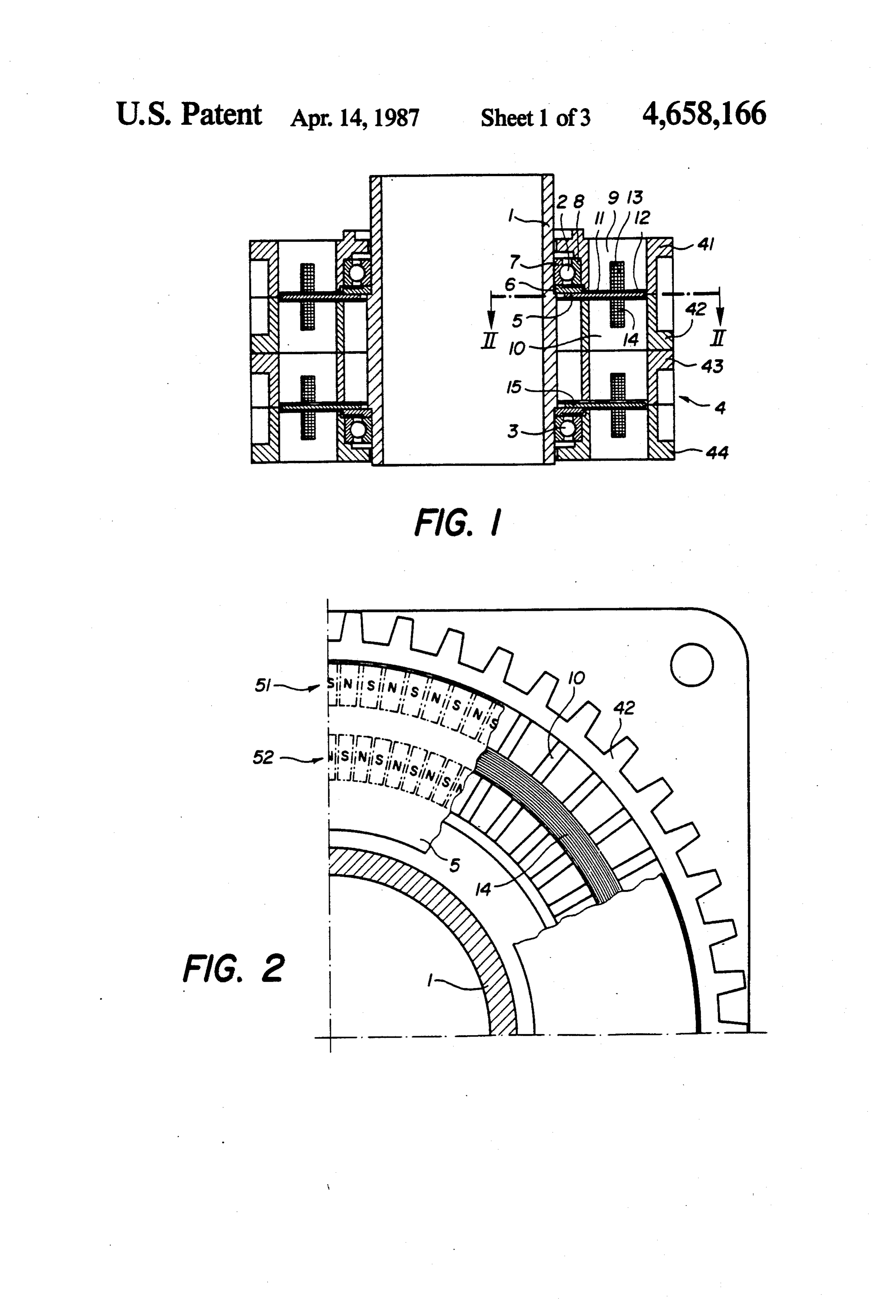
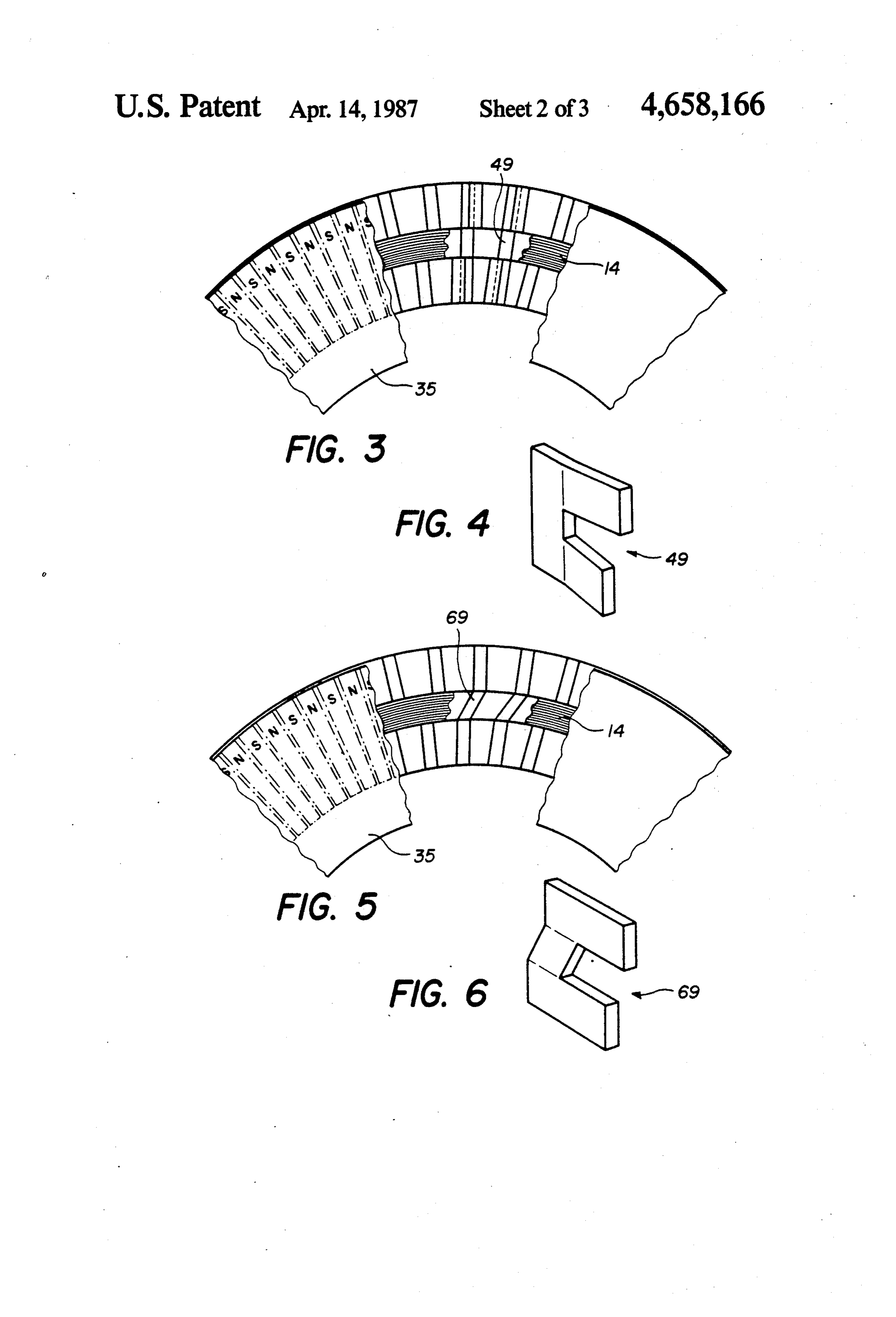

FIG. 7 is a partial sectional view, similar to a part of
FIG. 8 is a partial sectional view, similar to that of
Page 2drawing sheetscan →
Page 3drawing sheetscan →
Page 4drawing sheetscan →
Page 5scan →
FIG. 7 is a partial sectional view, similar to a part of
SYNCHRONOUSELECTRIC MOTOR WITH FIG. 1, showing another embodiment of an elementary DISC-SHAPED PERMANENT MAGNET ROTOR magnetic circuit;
FIG. 8 is a partial sectional view, similar to that of
Such a motor is described, for example, in U.S. Pat. 5 FIG. 1, corresponding to another constructional form No. 4,330,727. The original conception of this motor is of the motor, and adapted to motors of relatively small dimensions and of FIG. 9 is a sectional view, similar to that of FIG. 1, a power substantially smaller than 1 kilowatt. For mo showing an alternative embodiment of the motor shown tors having larger dimensions the structure as originally in FIG. 1.
provided appeared not to offer an optimal relationship 10 The motor shown in FIGS. 1 and 2 comprises a shaft between the torque produced and the size of the motor, 1 which, in this case, is a hollow shaft having a diameter especially as regards its radial dimension. which is relatively large in relation to the radial dimen The main object of the present invention is to provide sions of the motor. The shaft 1 is mounted to be rotat a motor of the mentioned type which provides a high able, by means of ball bearings 2, 3, in a stator assembly torque and a large number of steps per revolution, while 15 4 which is formed of two sub-assemblies comprising, having a minimum radial dimension. respectively, parts 41, 42 and 43, 44, which are, for To this effect, the motor according to the invention example, made of aluminum or a synthetic plastics ma has two pole parts of each of said magnetic circuits terial.
arranged at different radial distances on a same side of A first annular disc 5, of a magnetisable material such said magnetised rotor part, each elementary magnetic 20 as samarium-cobalt, is mounted by means of an annular circuit thus presenting two radially spaced air-gaps and support element 6 on the inner race 7 of the ball bearing co-operating with two concentric annular zones of said 2, this race being fast with the shaft 1. The outer race 8 magnetised rotor part, and said electrical energizing of the bearing 2 is mounted on the part 41 of the stator. coil being inserted into the space formed between said This part 41 comprises notches or slots in the radial pole parts of the magnetic circuits with which it is cou 25 direction of the motor, in which are placed flat U pled. shaped parts 9, made of a material having very good In a preferred embodiment of the invention, the rotor magnetic permeability. A second series of such U part is magnetised axially so as to present at least one shaped parts, indicated at 10, is placed in corresponding series of magnetic poles on each of its planar surfaces slots of the part 42 of the same stator sub-assembly. The and each elementary magnetic circuit comprises four 30 two arms of each “U” form pole parts, of which the free pole parts, disposed in pairs on both sides of said rotor ends present polar surfaces, the polar surfaces of one part so as to form two air-gaps at different radial dis pair of parts 9, 10 being disposed facing one another, so tances, one energizing coil and a yoke member being as to form air-gaps 11, 12. Coaxial, annular electric arranged on each side of the rotor part. energizing coils 13, 14 are disposed in such manner as to In an alternative embodiment, at least three pole parts 35 be inserted into the space formed between the arms of are located at different radial distances on a same side of the U-shaped members 9 and 10, respectively. Each pair said rotor part, connected in pairs by at least one yoke of parts 9, 10 constitutes an elementary magnetic circuit member and coupled with at least two concentric annu comprising two air-gaps and being coupled with the lar energizing coils of different diameters which each two coils 13 and 14.
pass between two pole parts, these latterforming part of 40 The annular disc 5 is magnetised in its axial direction, at least two elementary magnetic circuits co-operating so as to provide magnetic poles of alternate polarity, i.e. with the magnetic poles of at least three concentric N and S, on each of its surfaces, these poles being dis annular zones of said magnetised rotor part. tributed substantially regularly along two concentric According to the invention, a magnetic circuit clos annular zones 51, 52, which are indicated in FIG. 2. In ing part can be provided on one side of the rotor part 45 this Figure, the N and Spoles have been indicated by opposite the pole parts located on the other side of the chain-dotted lines. The dimensions of these poles are rotor part and, in particular, said circuit closing part can substantially equal to those of the pole surfaces formed be fast with the rotor part. by the ends of the arms of the U-shaped members 9 and Other features and advantages of the invention will 10, the radial distances of the two zones 51 and 52 corre become apparent from the following description of 50 sponding to the radial distances of the air-gaps 11 and 12 different embodiments, with reference to the accompa formed by the parts 9 and 10.
nying drawing, wherein: Since the poles of the magnetised annular disc are FIG. 1 is an axial section of a first embodiment of the distributed substantially regularly along each zone, the motor according to the invention; angular spacing of the median lines of the poles is sub FIG. 2 is a sectional view on the line II-II of FIG. 55 stantially at/N for a number of poles of 2N appearing in 1 and to a larger scale; each of the zones 51 and 52 on a same face of the disc. FIG. 3 is a partial sectional view, similar to a part of The mean angular spacing of the axial median planes of FIG. 2, of a first modified form of the motor shown in the elementary magnetic circuits 10 is at MN. The actual FIG. 1; spacing between two adjoining circuits may be slightly FIG. 4 is a perspective view of a “U”-shaped part of 60 different from this mean value, in order to compensate an elementary magnetic circuit which is used in the for the influence of certain harmonics of the torque of motor according to FIG. 3; the motor.
FIG. 5 is a partial sectional view, similar to that of The magnetic poles appearing at the pole surfaces of FIG. 3, in respect of a second modified form of the a member 9 or 10 under the effect of the current in the motor shown in FIG. 1; 65 coils 13 and 14, being differently named on a same side FIG. 6 is a perspective view, similar to that of FIG. 4, of the magnetised disc, the magnetic poles of the of a U-shaped part which is used in the modified form of magnetised disc disposed on a same side of this disc and the motor according to FIG. 5; having the same median line are also differently named.
Page 6scan →
In other words, the poles of same name to be found in also be fixed and spaced from the disc 85, like the part one or other of the two concentric zones 51 and 52, on 10 of FIG. 1.
a same face of the disc, are offset by 7t/N relatively to A structure similar to that of FIG. 1 is shown in FIG. one another, as will be seen in FIG. 2. 9, in which the same elements have been given the same The motor shown in FIG. 1 is a two-stage motor, the 5 reference numerals as in FIG. 1. In this structure, the first stage comprising the magnetised disc 5 and the pole parts of the elementary magnetic circuits, such as second stage, which is in fact similar, comprising a 95, 96, are interconnected by a common annular yoke magnetised disc 15, this latter co-operating with the part, formed for example by a laminated assembly, such sub-assembly of stators comprising the previously men as 97 in FIG. 9. Such an embodiment is of particular tioned parts 43 and 44. The structure of the second stage O interest, from the point of view of the manufacturing of is similar to that which has just been described in rela the parts and the assembling of the motor. tion to the first. Each stage thus constitutes, for exam I claim:
ple, one phase of a two-phase motor. 1. A synchronous electric motor, comprising at least It is to be noted that the form of the elementary mag one rotor part, substantially of annular disc form, netic circuits, such as described above, permits the use, 15 magnetised so as to present on at least one of its opposite for a given external diameter of the motor, of a magne planar surfaces at least one series of magnetic poles of tised disc of maximal diameter, and also the use of large alternating polarities, disposed regularly along at least magnetised zones on this disc. As a consequence, the efficiency and the output reach very high values for a one annular zone, said rotor part being mounted on a rotatable shaft, the motor additionally comprising at given size. least one assembly of several elementary magnetic cir FIGS. 3 and 4, on the one hand, and FIGS. 5 and 6, cuits of a magnetically permeable material and at least on the other hand, illustrate modified embodiments of one annular electric energizing coil coupled with said the motor shown in FIG. 1, in which modified embodi assembly of magnetic circuits, each of said circuits hav ments the poles appearing on each face of the magne tised disc 35 are of the same name in the same angular 25 ing at least one air-gap, and all of said air-gaps being arranged for co-operating with the said magnetic poles sector of the disc. It is therefore necessary to provide of an annular zone of said rotor part, each of said ele for an angular offsetting between the pole parts of each mentary magnetic circuits comprising at least two rect U-shaped member, such as 49 in FIG. 4 and 69 in FIG.
6. In the embodiment according to FIG. 4, the two pole angular and essentially flat pole parts, which are ar ranged substantially radially with respect to said shaft parts are bent from a straight-based portion, so as to 30 of the rotor, two pole parts of each magnetic circuit form an angle relatively to the latter and between them, being in the radial direction. According to FIG. 6, the two side ofarranged at different radial distances on a same pole parts are parallel to one another, and it is the base magneticsaid magnetised rotor part, each elementary circuit thus presenting two radially spaced portion of the member 69 which is bent, so as to provide air-gaps and the offsetting of the two pole parts. In both cases, the 35 zones of saidco-operating magnetised with two concentric annular rotor part, and said electrical magnetisation of the disc 35 is simplified because of the alignment and the continuity of the poles between the energizing coil being inserted into the space formed two annular zones co-operating with the pole surfaces between said pole parts of the magnetic circuits with of the U-shaped members. which it is coupled.
FIG.7 represents another embodiment of the elemen 40 2. A motor according to claim 1, comprising a rotor tary magnetic circuit, according to which three pole part magnetised axially so as to present at least one parts, such as 77, 78,79, are disposed on each side of a series of magnetic poles on each of its planar surfaces, magnetised disc 75, these three pole parts being con wherein each elementary magnetic circuit comprises nected to one another by a common yoke portion 76. four pole parts, disposed in pairs on both sides of said Two coaxial annular coils 73, 74 are coupled with the 45 rotor part so as to form two air-gaps at different radial W-shaped parts thus formed on each side of the disc 75. distances, one energizing coil and a yoke member being This latter has three concentric annular magnetised arranged on each side of the rotor part. zones on each of its faces, the poles formed in each 3. A motor according to claim 1, comprising at least angular sector being of same polarity in the exterior and three pole parts located at different radial distances on a interior zones, and being of opposite polarities in the 50 same side of said rotor part, connected in pairs by at middle zone, in conformity with the succession of the least one yoke member and coupled with at least two poles appearing on the pole surfaces of the parts 77, 78 concentric annular energizing coils of different diamters and 79. The coils 73 abd 74 are, of course, supplied in which each pass between two poles parts, these latter such manner that the same polarity appears on the com forming part of at least two elementary magnetic cir mon pole part 78. 55 cuits co-operating with the magnetic poles of at least The advantage of the constructional form in FIG. 7 is three concentric annular zones of said magnetised rotor a substantial increase in the torque of the motor by part.
means of a relatively small increase in the radial dimen 4. A notor according to claim 3, comprising a rotor sion of the latter. part magnetised axially so as to present, on each of its FIG. 8 illustrates a constructional form, of which the planar surfaces, at least one series of magnetic poles, and aim is to provide a particularly flat motor. In this case, comprising pole parts disposed in pairs on both sides of the elementary magnetic circuits are formed by a single said rotor part, so as to form an air-gap co-operating U-shaped part 89, which is arranged in a manner similar with a corresponding annular zone of said rotor part, to that shown in FIG. 1 and is coupled with a similar said yoke members and said annular coils being ar annular coil 83, the closing of the circuit being achieved 65 ranged on each side of the rotor part. by a yoke member placed on the opposite side of the 5. A motor according to one of claims 1 or 3, wherein magnetised disc 85. In the example of FIG. 8, this yoke each elementary magnetic circuit comprises, on one member 86 is fast with the magnetised disc, but it could side of the rotor part, a circuit-closing part which is 7 arranged opposite the pole parts located on the other part have axial planes of symmetry which are respec side of said rotor part. tively offset by an angle which is substantially equal to 6. A motor according to one of claims 1 or 3, wherein at/N, if 2N is the number of alternate positive and nega each elementary magnetic circuit comprises, on one tive poles of an annular zone of said rotor part, pairs of side of the rotor part, a circuit-closing part which is 5 poles of the same sign of respective concentric annular arranged opposite the pole parts located on the other zones being substantially aligned radially. side of said rotor part, wherein said rotor part is magne 9. A motor according to claim 2, wherein said yoke tised axially so as to present at least one series of mag member is formed by an annular part which is common netic poles on each of its planar surfaces, and wherein said circuit-closing part is fast with the rotor part. 10 to the pole parts disposed on a same side of said rotor 7. A motor according to claim , wherein said two part. 10. A motor according to claim 8, wherein said two pole parts of an elementary magnetic circuit, located at pole parts and a corresponding yoke member are different radial distances on a same side of said rotor part, have a same axial plane of symmetry, the magnetic formed by a substantially flat U-shaped member, the poles of same name or sign, respectively situated in one 15 two arms of the “U” forming the pole parts being bent and the other of the said concentric annular zones of in relation to the yoke member for achieving the offset said rotor part being offset relatively to one another by ting of their planes of symmetry. an angle substantially equal to iT/N, if 2N is the number 11. A motor according to claim 8, wherein said two of alternate positive and negative poles of an annular pole parts and a corresponding yoke member are ZO. 20 formed by a substantially flat U-shaped member, the 8. A motor according to claim 1, wherein said two yoke member being bent in order to effect the offsetting pole parts of an elementary magnetic circuit, located at of the two pole parts formed by the arms of the “U”. different radial distances on a same side of said rotor . . . . .
Provenance
- Collection
- Patents citing this work
- Pages
- 7
- Method
- pdftotext (the PDF's own text layer) + pdftoppm 300dpi page scans
- Patent office record
- patents.google.com →
- Source
- Google Patents citing-documents table
- Assignee
- Portescap
- Published
- 1987-04-14
- Transcribed from
- patentimages.storage.googleapis.com →