

patent · US4665895A
Ellipsoidal solar dish concentrator
19 May 1987
Text
Page 1bibliographic recordscan →
United States Patent (19)
Meier
54 ELLIPSOIDAL SOLAR DISH
CONCENTRATOR
75 Inventor: Rudolf H. Meier, Santa Ana, Calif.
73 Assignee: McDonnell Douglas Corporation,
Long Beach, Calif.
Int. Cl."................................................. F24J 2/10 52 U.S. Cl. .................................... 126/438: 126/449;
3,134,906 5/1964 Henker ............................ 126/438 X
4,018,212 4/1977 Hein et al. ........................... 126/51
4,099,516 7/1978 Caulier . -
4,452,232 6/1984 David ............................. 126/451 X
FOREIGN PATENT DOCUMENTS
Primary Examiner-Larry Jones
Attorney, Agent, or Firm--Benjamin Hudson, Jr.;
George W. Finch; Donald L. Royer
A solar dish concentrator is provided having a rotation ally symmetrical elliptical shape for focusing an uni form flux density of solar radiation on a receiver. The solar flux pattern reflected to the receiver is evenly distributed over the four quadrants of the receiver with out containing any hot spots.
12 Claims, 6 Drawing Figures
Drawings
Page 2drawing sheetscan →
Page 3drawing sheetscan →
Page 4drawing sheetscan →
Page 5scan →
of this invention. The solar dish concentrator 10 has a
ELLPSODAL SOLAR DISH CONCENTRATOR design based on the ellipsoid's properties of finite conju gate imagery. It is rotationally symmetrical and is de
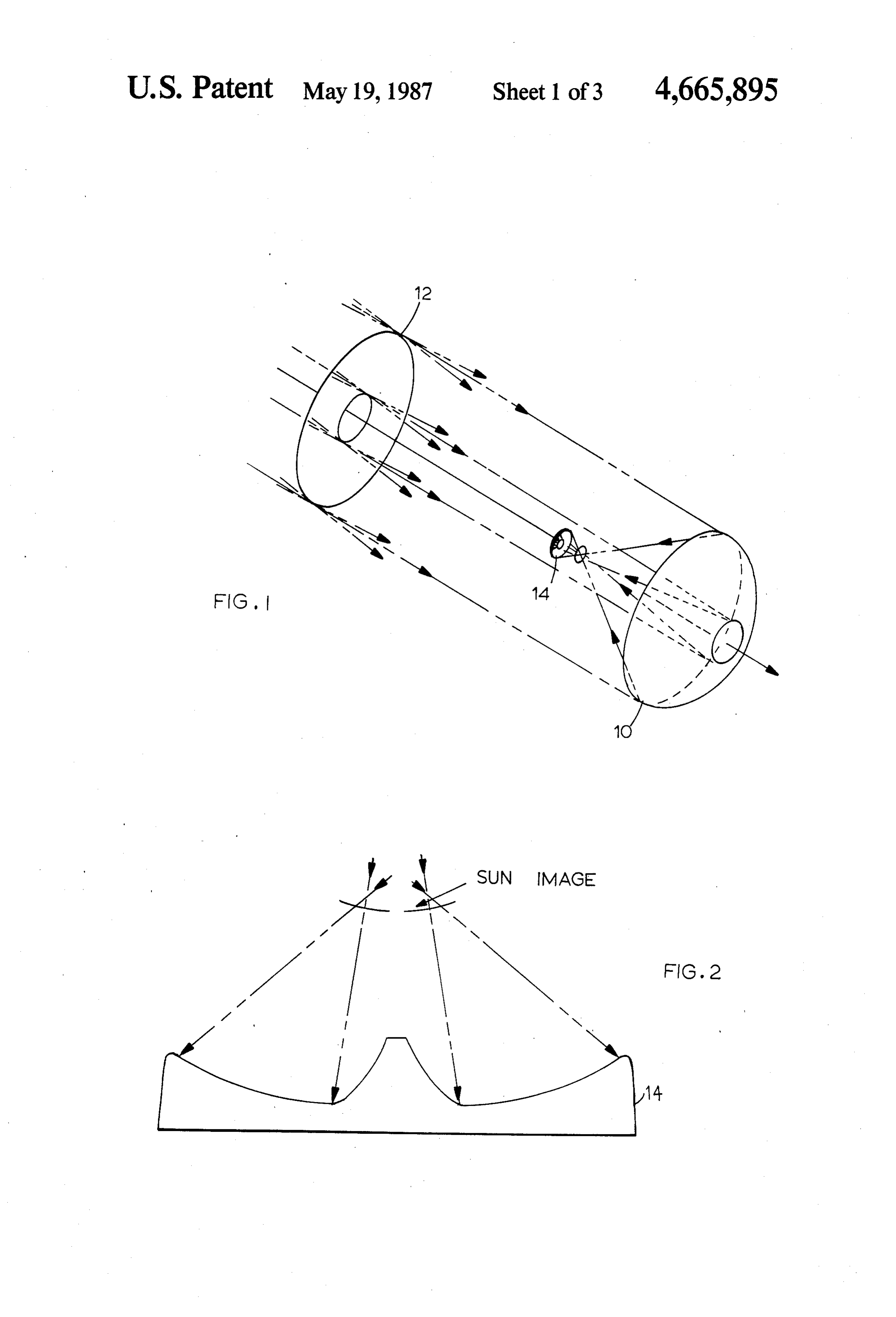
BACKGROUND OF THE INVENTION signed to focus a uniform flux image of an annulus 1. Field of the Invention shaped plane on an annulus shaped receiver body. In This invention relates generally to solar dish concen stead of forming a perfect image of the sun at its focal trators that focus solar radiant energy upon a collector point as the traditional concentrators do, it is designed and more particularly to an ellipsoidal concentrator that to form an image of an imaginary annulus shaped object projects an uniform radiant flux onto an annulus shaped O plane 12 at the surface of the concave annulus shaped receiver body. receiver body 14. The object plane 12 is located at some 2. Description of the Prior Art distance in space between the sun and the concentrator Solar energy collecting apparatus is well-known in 10. Since this plane is uniformly irradiated by the sun, the art. Traditional solar collectors utilize a reflector with properly designed optics its image will also have a which focuses solar energy upon heat exchanging appa 15 uniform radiant flux pattern. The shape of the typical ratuses. The reflector may be a parabolic, elliptical, or a receiver body 14 is shown in FIG. 2. circular cylindrical type mirror. The efficiency of the The object plane 12 is located at a distance from the traditional solar collector is determined by the percent concentrator that corresponds to the distance to the age of incident solar radiation that can be focused on the concentrator's far focal point. The required demagnifi heat exchanging apparatus. The heat exchanging appa ratus normally consists of tubes located at the focus 20 cation is the ratio of the object annulus width to the receiver annulus width, ROBJ/RIMG, where ROBy is the point of the solar collector which carry a heat conduct width of the object annulus 12 and RIMG is the width of ing fluid.
The principal object of prior art solar collectors is to the image annulus. The demagnification determines the ratio of the ellipsoid's far focal point distance to its near focus a maximum amount of solar radiation to a single focus point where the heat exchanging apparatus is 25 focal point distance, measured from its vertex. Opti located. To accomplish this, various collector shapes cally, an ellipsoid will form a better, more uniform have been utilized and in addition sun tracking systems image of an object that is located at a finite distance than have been used to control the angle of incident solar either a spheroid or a paraboloid. The image of an ex radiation to maximize the efficiency of the system. tended plane will, of course, not be perfect, but this will New receiver-solar engine combinations based on the 30 have very little or no effect on the uniformity of the Sterling Engine Principle have been developed that overall flux distribution across the image. The rather require a uniform flux density having a peculiar shape of simple design approach shown in FIG. 1 makes the the concentrated solar flux pattern which can best be concentrator an ellipsoid whose far focal point FOBylies described as a concave annulus. These new receivers at the center of the object plane annulus 12 and whose require that the solar radiation be evenly distributed 35 near focal point FIMG thus coincides with the center of over the four quadrants of the receiver without any hot the annular receiver body 14. The central cone section spots. The traditional concentrators cannot meet these of the annular receiver body 14 should not be apprecia demands. A variety of paraboloidal and spheroidal con bly irradiated. In this configuration, the perfectly im centrators have been developed, but none have been aged conjugate points FOBJ and FIMG would be ob completely successful at creating the proper flux pat scured and thus not actually contribute to the image. tern. It would be desirable if a solar dish concentrator Also, this would require matching the sides of the cen were provided that focused a uniform flux density on a tral obscured area of the concentrator to that of the receiver. forbidden central cone section of the receiver body, resulting in undesirable large concentrator obscuration
There is provided by this invention a solar dish con (about 3.0 meter diameter for an 11.0 meter diameter centrator based on the ellipsoid's properties of finite dish or about 7.5%).
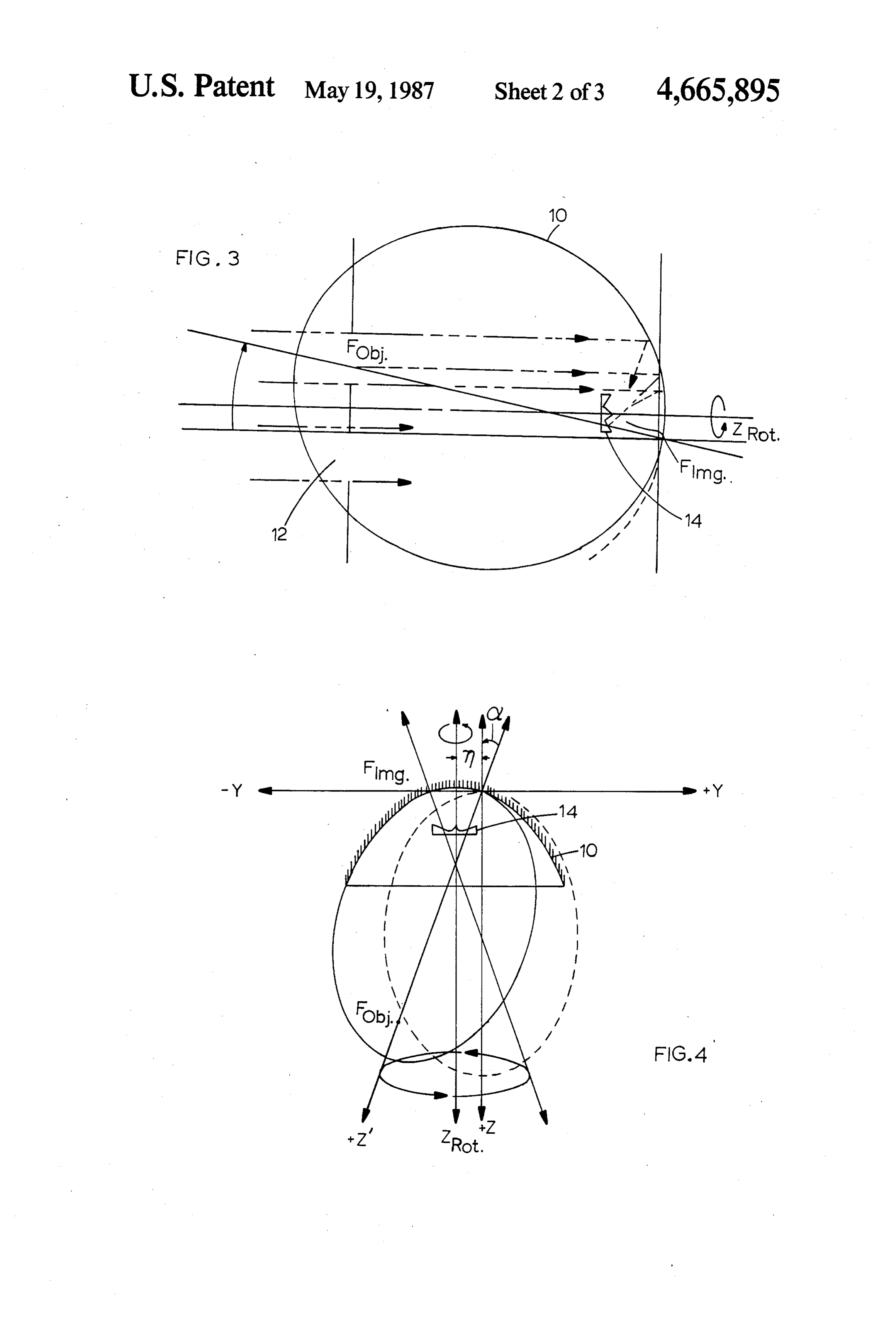
conjugate imagery. It is rotationally symmetrical and is Referring to FIG. 3, a better approach of almost designed to focus a uniform flux image of an annulus conjugateequal simplicity is shown that makes FOBJ and FIMG shaped plane on an annulus shaped receiver body. 50 ring zones. This can be achieved by tilting the ellipse formed by a cut through the center plane of
BRIEF DESCRIPTION OF THE DRAWENGS the ellipsoid slightly such that FOBy lies either inside or FIG. 1 illustrates an elliptical solar dish concentrator at one periphery of the object plane annulus 12 and FIMGlies inside or at the corresponding periphery of the incorporating the principles of this invention;
receiver body annulus 14, but of course at the opposite
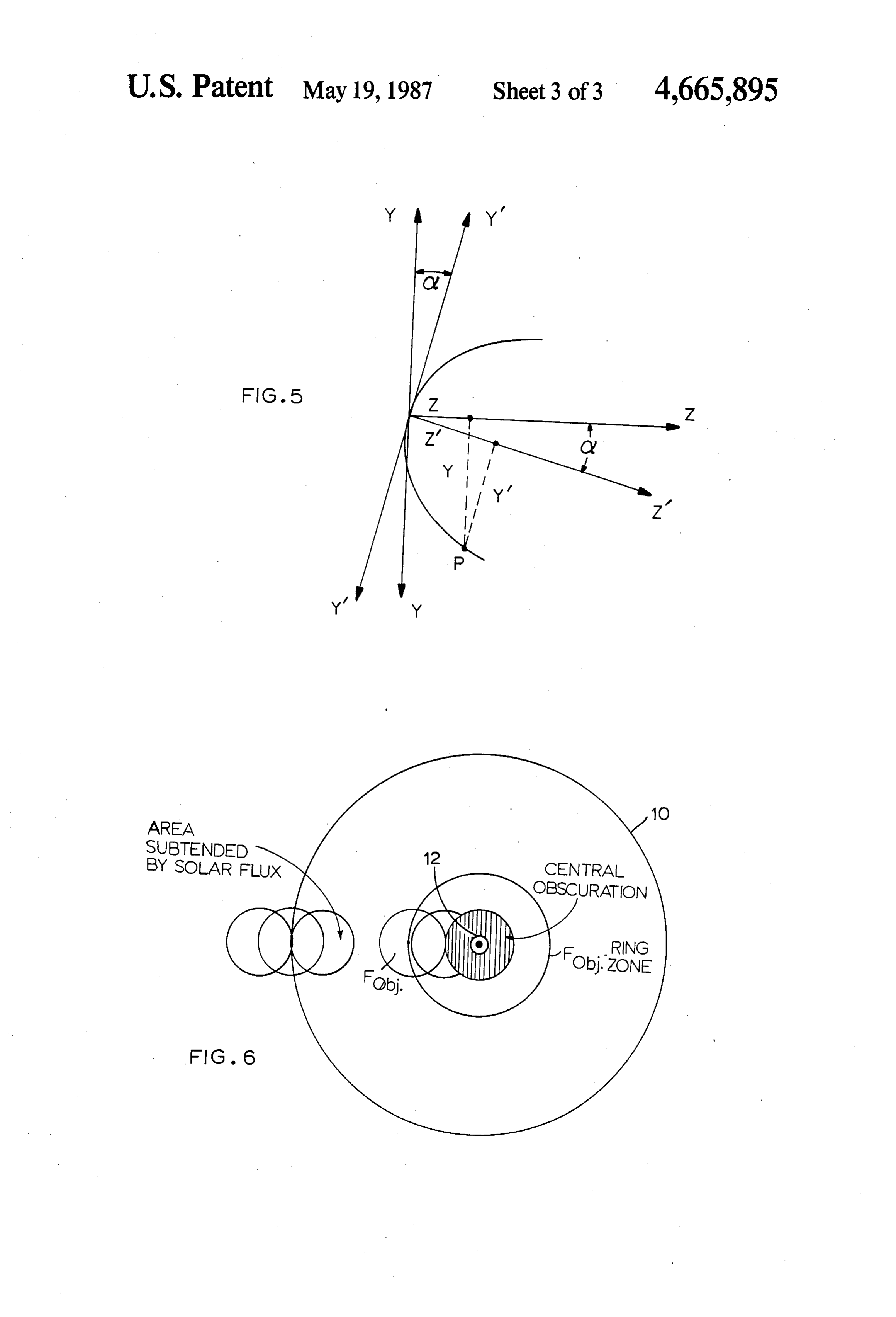
FIG. 2 illustrates a typical concave annulus receiver 55 side body; of the optical center line. This is permissible due to FIG. 3 illustrates a tilted ellipsoid solar concentrator; the small angular subtense (32 minutes of arc) of the sun FIG. 4 illustrates the generation of the ellipsoidal radiation. No radiation originating from one side of the concentrator's surface; object plane annulus 12 can reach the opposite side of FIG. 5 illustrates the transformation of the ellipsoidal 60 the concentrator. If this tilted ellipse is now rotated concentrator coordinates; and about an axis that is parallel to the original Z axis, but FIG. 6 illustrates the radial vignetting of the ellipsoi shifted side ways to go through the center of the re dal concentrator. ceiver body, thus forming the optical centerline of the dish, the surface created by the convolution of its out
BRIEF DESCRIPTION OF THE PREFERRED 65 ward tilted quadrant will be that of the desired dish EMBODIMENT concentrator. The location of the center of the receiver Referring to FIG. 1, there is shown an ellipsoidal body 14 can be found by considering that the foci of the solar dish concentrator 10 incorporating the principles tilted ellipse must coincide with both selected conju 6 gates of the object plane annulus 12 and the receiver TABLE 1. body annulus 14. BASELINE PARAMETERS The most useful form of the general equation of an Overal Diameter OO in ellipse for optical application is Obscured Central Section 2.00. In Total Collecting Area 91.89 m2 y2-2rz--Pz?=0 (i) Object Plane annulus
Outer Diameter 1.00 in
In this form the ellipse is tangent to the y-axis at the Inner Diameter 2.00 m vertex and symmetrical about the z-axis (dotted ellipse Receiver body Annulus in FIG. 4). The constants in Eq. (1) are 10 Outer Diameter 0.4 m Inner Diameter 0. In r= radius of curvature at the vertex (y= z = 0) Demagnification 30 x P= 1-e2(P)0 for ellipse) Basic Ellipse e= numerical eccentricity = c/a Near Focus FIMG 7.00 m c=linear eccentricity Far Focus FOBy 210.00 m a=major half-axis (coincident with z-axis for 0<P<l) Major Semi-Axis a = (FIMG + FOBJ) = 08.50 in
Linear Eccentricity e = c/a 0.93548
If the ellipse is now tilted clockwise about the x-axis PRadius of Curvature at Vertex in the yz-plane through an angle a, the yZ-coordinate Dish system will appear to be rotated counterclockwise PlaneArea Point
Diameter Irradiated from Object 1.95 in through angle minus a and thus be transformed as fol 20 Fiux Rise Dimension Across Peripheries of 0.06 in lows (FIG. 5) Receiver
Tilt Angle of Basic Ellipse (see FIGS. 3 and 4)
z'=z cos a -y sin a or z=z' cos a-y" sin a 25 Sun Image Distance from Vertex of 677.4 cm y'-y cos a-z sin a or y = y' cos d+z' sin a Parallel Shift of z Axis of Ellipse to zRoT (FIG. 4) m = 0.088 - 7 sina. = 0.60 m
Eq. (1) now transforms to Diameter of Ring Shaped Image of a point at 4.2 cm the cent of the object plane.
P(z' cosa-y" sin a)=0 With no physical aperture stop at the object plane 12, the annular image at the receiver body 14 will exhibit radial vignetting because of the dish's finite aperture
Rotating the outward tilted quadrant (negative y-val and central obscuration.
ues) of the ellipse about an axis called ZROT(FIG. 4) will 35 It has been found that the geometric image spot size generate the desired surface of the concentrator. Nam of ech point of the object plane annulus varies very little ing the parallel shift of the z-axis to ZROT, m, the equa with its literal distance from FOBJ, the ellipses far local tion defining the concentrator surface can be written point. Thus, it can be expected that the surface defined by Eq. (3) promises to generate not only a flux pattern (3) of high circular uniformity but also of high radial uni formity.
The magnitude of angle o and with it the magnitude andThe first order estimate of permissible manufacturing alignment errors will be given in the next section.
of m depends on the selected location of FOBy within the object plane annulus 12. At first giance, a good choice alignment tolerancesareforallowable 45 The following the manufacturing and concentrator 10. The most of the ring zone that should be imaged perfectly would damaging surface errors are obviously departures from be a median ring somewhere between the inner and the circular symmetry of the concentrator. Fortunately, outer periphery of the annulus (see e.g., FIG. 3), but this symmetry is relatively easy to achieve and also to since the image of a plane surrounding the far focal 50 maintain.
point of an ellipsoid forms a spherical surface around its More difficult to generate and to maintain is the shape near focus with a radius of curvature which very of the z = f(y) curve. In order to get some feeling for closely matches that of a typical concave receiver body how much departure from the ideal curve can be toler 14, it appears to be more prudent to let FOBJ be the ated, the actual value of z at the dish periphery (y=5.5 innermost ring that irradiates the dish without vignett 55 m) will be given for a sphere, a parabola, a non-tilted ing (FIG. 6). This in turn causes FIMG to coincide with ellipse and a tilted ellipse.
the inner fully irradiated ring zone of the receiver body 1. Sphere annulus 12. The equation for a sphere that is tangent to the y-axis Since there is no actual physical aperture stop at the at Zac0 is location of the fictitious object plane 12, the radiant flux 60 (z-r)2-y2 = r (4) reflected by the concentrator toward the receiver body will show vignetting (FIG. 6). The radial rise from zero Setting r = 13.5 m and y = 5.5 m (from Table 1) yields to maximum flux and conversely is determined by the Z= 1.171 m.
subtense of the solar angle at the concentrator for radia tion thought to emerge at the object plane. 65 2. Parabola
The major baseline parameters of a representative The equation for the equivalent parabola is concentrator based on the foregoing design principle are listed in Table 1.
Page 7scan →
ing means coincides with the center of the gener
With the same values for r and y one obtains ally concave annulus shaped receiver means. 2. A device for collecting and concentrating radiant za 1.120 m energy as recited in claim 1 wherein the receiver means is a generally concave annular shape comprised of a 3. Non-Tilted Ellipse generally conical center section protruding therefrom. The non-tilted ellipse is defined by Eq. (1). Again, 3. A device for collecting and concentrating radiant from Table 1, setting r= 13.5 m, y = 5.5 m, and energy, comprising:
P=0.12487, yields (a) A generally ellipsoidal rotationally symmetrical 10 reflecting means having a near focal point and z c.126 m having a configuration generated by rotating a tilting elliptical plane whereby the axis of rotation 4. Tilted Ellipse is shifted from the vertex for focusing radiant en The tilted ellipse is defined by ergy into a uniform flux pattern from a radiant (6) (b) A receiver means mounted in close proximity to the reflecting means for receiving the focused radi
From Table 1: cos as 0.999947, sin a = -0.00297, ant energy, said receiver having a concave annulus y'- m = -5.66 m. shaped surface mounted near the focal point of the This yields 2O reflecting means such that the near focal point of the reflecting means coincides with the center of
Z= 1.135 m. the generally concave annulus. 4. A device for collecting and concentrating radiant
Thus, the difference in Z of a non-tilted paraboloid energy as recited in claim 3 wherein the far focal point and a tilted ellipsoid at the outer rim of the concentrator 25 of the reflecting means is inside of an imaginary annular is object plane located between the radiant source and the reflecting means.
Azia: 5 mm. 5. A device for collecting and concentrating radiant energy as recited in claim 4 wherein the near focal point
This suggests that on a realistic basis the error in Z at 30 of the reflecting means is inside of the generally con the outer rim should be held within 3 mm. An error of cave annular shaped receiver means. 3 mm in z can roughly be translated into an angular 6. A device for collecting and concentrating radiant error of the surface normal of about 0.6 mrad or an energy as recited in claim 5 wherein receiver means is a angular beam deviation of 1.2 mrad. This corresponds generally concave annular shape comprised of a gener at the receiver body surface to a radial blur of about 35 ally conical center section protruding therefrom. -8.4 mm, a quite acceptable value. 7. A device for collecting and concentrating radiant Obviously, since the concentrator will have to be energy as recited in claim 4 wherein the receiver means fabricated and assembled from smaller mirror segments, is a generally concave annular shape comprised of a one should require that the surface contour of each generally conical center section protruding therefrom. segment deviates not more that about 0.5 millimeter 40 8. A device for collecting and concentrating radiant from its prescribed value. Assuming replica type manu energy as recited in claim 3 wherein the far focal point facturing methods, this tolerance appears to be rather of the reflecting means is one periphery of an imaginary easy to maintain. annular object plane located between the radiant source Although there has been illustrated specific detail and and the reflecting means.
structure of operation, it is clearly understood that the 45 9. A device for collecting and concentrating radiant same were merely for purposes of illustration and that energy as recited in claim 8 wherein the near focal point changes and modifications may be readily made therein of the reflecting means is one periphery of the generally by those skilled in the art without departing from the concave annular shaped receiver means. spirit and scope of this invention. 10. A device for collecting and concentrating radiant What I claim is: 50 energy as recited in claim 8 wherein the receiver means 1. A device for collecting and concentrating radiant is a generally concave annular shape comprised of a energy, comprising: generally conical center section protruding therefrom. (a) A rotationally symmetrical elliptical reflecting 11. A device for collecting and concentrating radiant means for focusing radiant energy into a uniform energy as recited in claim 9 wherein the receiver means flux image of an annulus-shaped object plane from 55 is a generally concave annular shape comprised of a a radiant source said reflecting means having a near generally conical center section protruding therefrom. focal point; and 12. A device for collecting and concentrating radiant (b) A generally concave annulus-shaped receiver energy as recited in claim 3 wherein the receiver means means mounted between the radiant source and the is a generally concave annular shape comprised of a reflecting means for receiving the focused radiant 60 generally conical center section protruding therefrom. energy such that the near focal point of the reflect k ck se s s
Page 8scan →
United states patent and trademark office
Certificate of correction
NVENTOR(S) : Rudolf H. Meier it is Certified that error appears in the above-identified patent and that said Letters Patent is hereby Corrected as shown below:
Column 4 line 37, the word "ech" should be line 38, the word "literal" should be -e elateral -- line 38, the word "local" should be
Column 6, line l.2 (Claim 3) the Word "tilting" should be -- tilted---
Signed and Sealed this
Twenty-ninth Day of September, 1987
Attest.
Donald j. quigg
Attesting Officer Commissioner of Patents and Trademarks
Provenance
- Collection
- Patents citing this work
- Pages
- 8
- Method
- pdftotext (the PDF's own text layer) + pdftoppm 300dpi page scans
- Patent office record
- patents.google.com →
- Source
- Google Patents citing-documents table
- Assignee
- Mcdonnell Douglas Corporation
- Published
- 1987-05-19
- Transcribed from
- patentimages.storage.googleapis.com →