

patent · US4674476A
Solar heating and cooling apparatus
23 June 1987
Text
Page 1bibliographic recordscan →
United States Patent (19) 11 Patent Number: 4,674,476 Wilson 45 Date of Patent: Jun. 23, 1987 54 SOLAR HEATING AND COOLING 3,964,678 6/1976 L'Hanlon ........................ 126/270 X
APPARATUS
FOREIGN PATENT DOCUMENTS
Inventor: Neill R. Wilson, P.O. Box 538, 5291.63 7/1920 France . Berryville, Va. 22611 1069317 7/1954 France .
21 Appl. No.: 557,414 Primary Examiner-William E. Tapolcai 22 Filed: Nov. 30, 1983 Attorney, Agent, or Firm-Fay, Sharpe, Beall, Fagan, Minnich & McKee
Related U.S. Application Data (57) ABSTRACT (63) Continuation of Ser. No. 581,134, May 27, 1975, aban Solar heating and cooling system comprising an insu doned.
lated fluid containing tank positioned with a portion Int. Cl.................................................. F24J 2/24 thereof disposed above and below ground level. The 52 U.S. Cl. .................................... 126/434; 126/435; system includes apparatus for transferring heat between 126/436; 126/452; 165/45 the tank and the atmosphere, and to or from the subter 58 Field of Search ................................ 126/433-437, ranean earth in close proximity of the tank. Baffle means 126/452; 62/235.1, 260; 165/45 X located within the tank are specially arranged to cause (56) References Cited fluid contained therewithin to be circulated in a manner
dissipated into the tank fluid. Means may also be pro 1,425,174 8/1922 Carter et al. ....................... 126/271 vided for directing the flow of the fluid to and from the 1,571,100 1/1926 Skinner ........... ... 62/260 X tank to an outside heat exchanger for heating or cooling 1,703,392 2/1929 Elliott ......... ... 62/260 X a building so that when the temperature within the tank 2,064,345 12/1936 Hodgson ............................. 126/434 2,202,756 5/1940 Cline ....... 126/434 X reaches a predetermined value relative to the tempera 2,213,894 9/1940 Barry ................................... 126/419 ture of the inside of the building, the flow is directed in 2,396,338 3/1946 Newton .. ... 126/271 X a manner to accomplish either heating or cooling as 2,490,659 12/1949 Snyder ................ ... 126/271 X may be desired in accordance with the season of the 2,529,154 1 1/1950 Hammond et al. ................... 62/2X year. Energy may be transferred from the outside heat 2,749,724 6/1956 Borgerd et al. .... ... 165/45 X exchanger to or from the interior of the building by 2,793,509 5/1957 Keen ..................................... 62/260 3,563,305 2/1971 Hay ............. ... 126/434X means of a heat pump type reversible refrigeration sys 3,812,903 5/1974 Thomason ...... ... 126/400X tem.
3,908,753 9/1975 Balch ................................ 165/45 X 3,919,998 11/1975 Parker ............................. 126/271 X 31 Claims, 5 Drawing Figures
Drawings
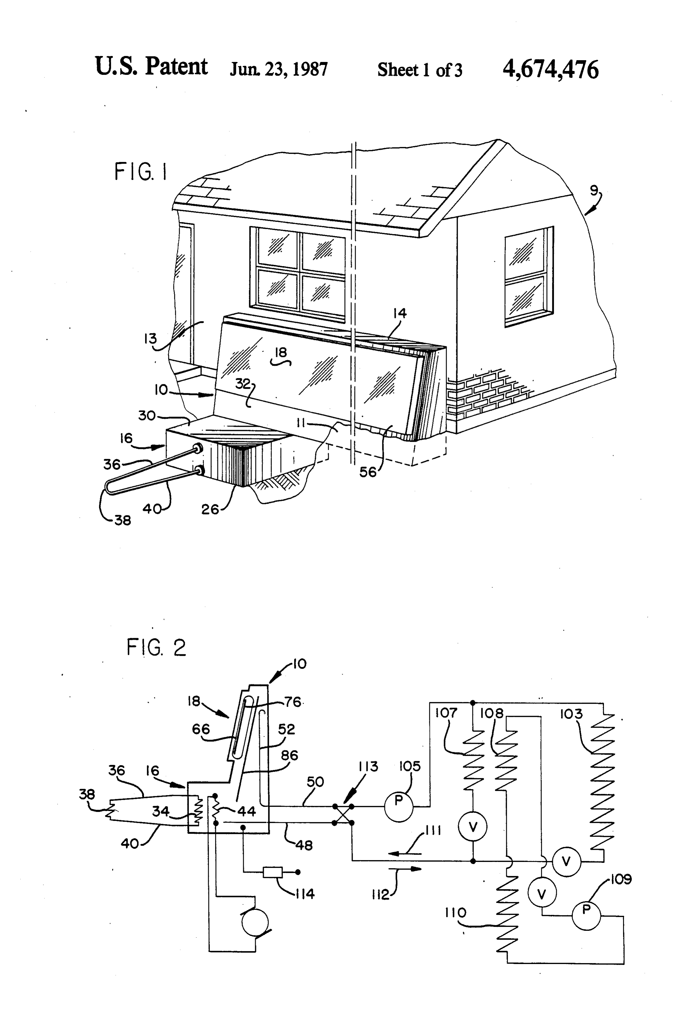
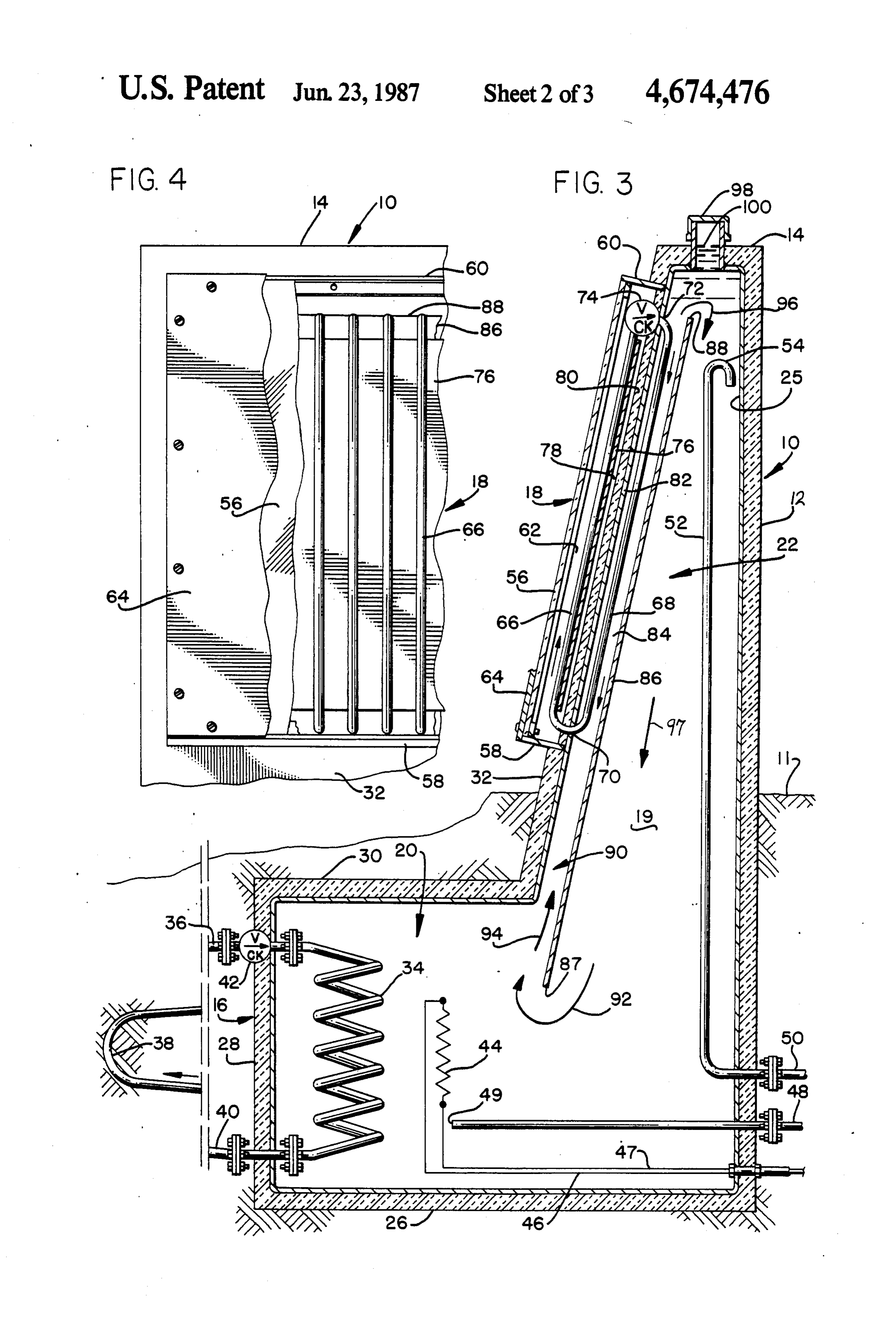
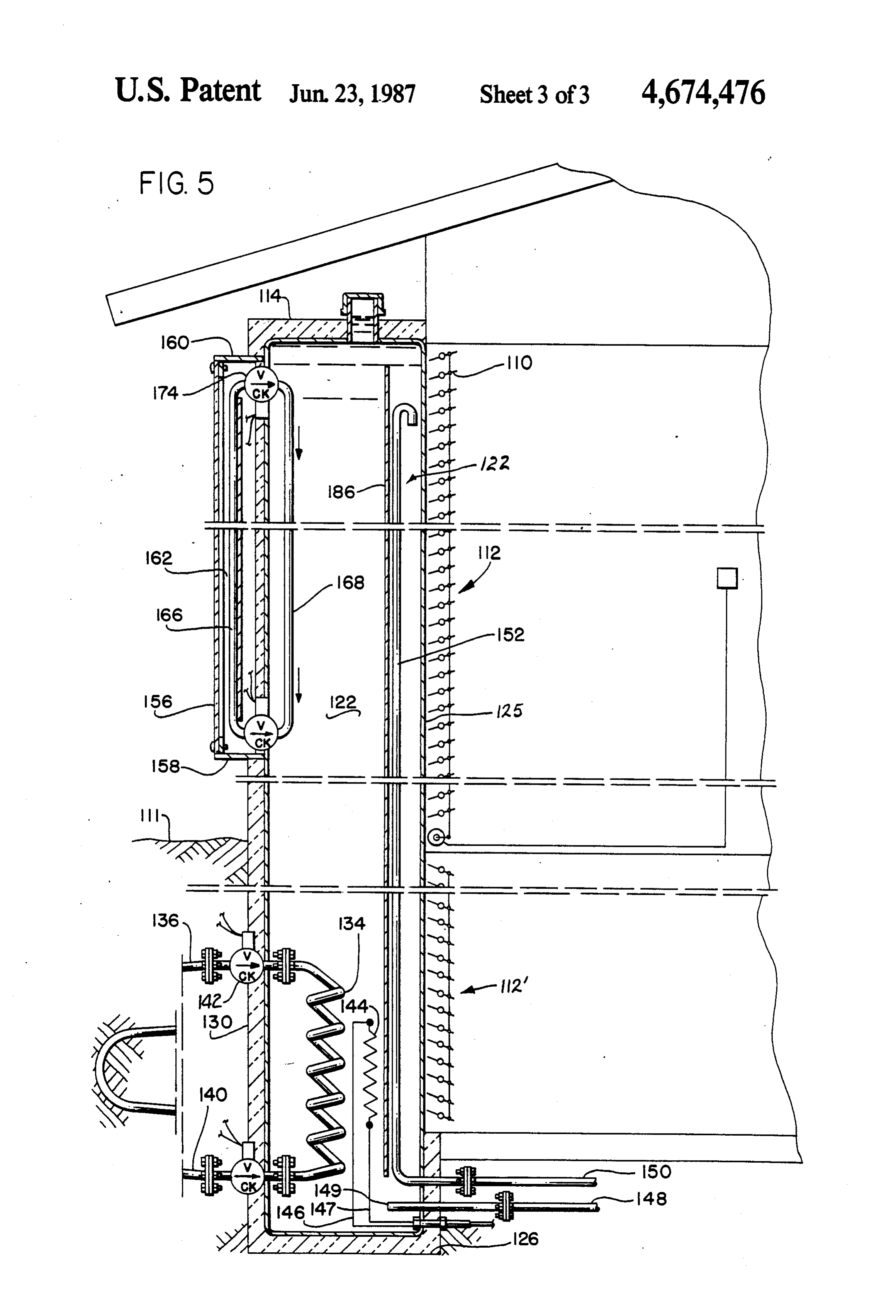
FIG. 1 is a perspective view of a building having 35 available local energy sources.
Page 2drawing sheetscan →
Page 3drawing sheetscan →
Page 4drawing sheetscan →
Page 5scan →
generally vertically disposed liquid filled closed loop,
SOLAR HEATING AND COOLING APPARATUS or series of loops, of connected marginal lengths of conduit located within and without the vessel so that
This application is a continuation of application Ser. the solar heat collector transfers heat energy from the No. 581,134, filed May 27, 1975, now abandoned. 5 sun into the fluid contained within the tank. Baffle BACKGROUND OF THE INVENTION means are provided within the vessel and causes fluid within the tank to assume a definite circulation pattern
In many regions of the world, there is a need for as heat is imparted thereinto, so that relatively hot fluid heating in the winter and cooling in the summer, and a migrates to the top of the vessel while relatively cool vast amount of energy is consumed during both seasons O fluid migrates to the bottom thereof. for these purposes. Nature abounds with many different A second heat collecting and dissipating closed loop forms of useful energy which are ignored by man, but conduit has a marginal length thereof disposed within which could be taken advantage of during both the and without an underground wall member or structure warm and cold seasons to aid with both heating or of the vessel so that heat transfer is effected between the cooling of an environment. This advantage can be real 15 fluid contained within the vessel and the surrounding ized quite economically by the provision of a system subterranean area.
made in accordance with the present invention which Accordingly, when the fluid within the vessel falls can be conveniently installed adjacent to or forming below the temperature of the surrounding underground part of a structure such as a home, garage, fence, or the area, natural circulation is effected respective to the like. 20 fluid contained within the vessel; and, when solar heat is Furthermore, the present invention can be fabricated available, the solar collector system transfers heat from into a packaged unit which can be trucked to the instal the collection surface into the fluid contained within the lation site where it can be readily installed without tank, and as heat is transferred thereinto a natural circu destruction or modification of existing structure. lation is established.
Broadly, the preferred embodiments of the present 25 Fluid conduits may be employed to conduct the invention comprises an insulated fluid containing vessel heated fluid from the tank or vessel to a heat exchanger that extends above and below the ground level with located remote from the vessel. The heat exchanger can components thereof extending from the underground take on several different forms and can be in the form of portion of the vessel to provide a closed looped fluid a radiator for directly heating a home, or it may ex conveying system disposed in a manner such that natu 30 change heat to the evaporator of a heat pump, or from ral circulation is effected as heat is transferred into the the condenser of a heat pump, as may be desired accord fluid contained within the vessel. One wall of the above ing to the various embodiments of the invention. ground portion of the vessel is built in the form of a Accordingly, a primary object of the present inven solar heat collecting unit which also employs a closed tion is the provision of a combination heat collecting loop heat collecting and dissipating system connected in 35 and dissipating apparatus which utilizes both solar and heat transfer relationship to the vessel fluid in such a subterranean heat sources.
manner that both the system and the tank liquid are Another object of the invention is to provide appara self-circulating, thereby causing heat from the solar tus for heating and cooling which employs a closed collection surface as well as possibly from the subterra looped system for imparting natural circulation into a nean earth to be transferred into the fluid contained fluid contained within a tank. within the vessel. A still further object of this invention is to provide a The fluid contained within the vessel is self-circulat solar and subterranean heat collector which absorbs ing and this is accomplished by allowing the cooler fluid solar energy in the day and subterranean energy at to flow downwardly and the warmed or warmer fluid other times if the temperature of the fluid within the to flow upwardly as it is heated. 45 storage tank is lower than that of the subterranean It is known that the subterranean temperature in the earth.
area of four to six feet below ground level remains Another and still further object of this invention is to around 52 to 57 Fahrenheit for most geographical provide a combination solar and subterranean heat col locations in the United States. Accordingly, the under lecting system having fluid conducting closed loop ground closed loop system will impart self-circulating 50 piping systems arranged respective to a fluid containing action into the tank when the temperature of the fluid vessel and having check valves in said systems and a within the vessel falls below or above the subterranean baffle in said vessel so that natural circulation of the temperature. fluid in the closed loop systems causes heated fluid to The present invention is advantageously used in com rise in said vessel and thereby keeps the fluid in the bination with a heat pump type heating and cooling 55 vessel aggitated to prevent stagnation spots or layers. system where the evaporator collects heat from the A still further object of this invention is to provide a fluid which is then pumped to the condenser of the heat generally large flat insulated vessel that is built into a pump. wall or roof of a building and wherein a portion thereof SUMMARY OF THE INVENTION may extend below the ground level. The outside wall of the unit is built in the form of a solar or atmospheric
This invention relates to a solar type heating and heat collecting and dissipation unit wherein a closed cooling apparatus and specifically to heat collecting loop or a plurality of closed loop heat collecting and apparatus comprising an upstanding tank or vessel hav dissipating conduits are connected in heat transfer rela ing a lower portion thereof located below ground level tionship to the atmosphere on the outside and to the and an upper portion thereof located above ground 65 fluid on the inside of the unit, and wherein an area of the level. In the preferred embodiment of the invention, an wall of said vessel on the inside of the building is uninsu above ground wall structure is made in the form of a lated and is provided with a surface to promote radiant solar heat collector and dissipator, and comprises a energy directly into the interior in the event heating is 6 desired, or receive radiation from the building interior outwardly directed lower foot portion 16. An inclined in the event cooling is desired. The degree of radiation forwardly positioned wall has a solar collector assembly heat transferred in either direction being regulated by a 18 formed therein and disposed in such a manner that set of louvers which may be controlled by a thermostat, solar energy can be ingested thereinto when the sun for example. impinges thereon. The various walls of the structure In the event the unit is built so that it is adjacent to or define a tank having a main fluid holding chamber 19, a below ground level then the subterranean heat collect lower forward chamber 20, and an elevated chamber 22 ing or dissipating system as used before can be com each of which are in fluid flow communication with one bined with the solar or atmospheric collecting or dissi another.
pating systems. 10 In the embodiment of FIGS. 1-4, the walls of the Another embodiment of the invention is the provision apparatus preferably comprises an impervious steel or of a heat pump combined with a system of the invention metallic inner wall surrounded by foam insulation to utilize the system completely and allow it to cool which exhibits a high K value so that indiscriminate when the storage fluid temperature rises too high for heat transfer between the liquid contained within the direct cooling and to heat when the storage temperature 15 vessel relative to the ambient is minimized. gets too low for direct heating. In some areas this sys A lower wall 26 bottom supports a substantial tem is capable of providing all of the heating and cool amount of the apparatus while the front wall 28 defines ing functions directly without the need of the heat the extent of the forward chamber, or foot. A ledger, or pump. Such an integral wall or roof unit as contem horizontally directed forward wall 30, joins together plated by the invention is built directly into a home 20 the sloped wall 32 and the outer wall of the foot. A first during construction thereof with a design adapted to closed loop heat exchanger 34 is illustrated as being in such a fluid containing wall section or panel rather than the form of a coil and includes a subterranean heat being of utility on existing building structures. transfer conduit 36, 38, 40 connected to the coil 34 by These and various other objects and advantages of means of a remote controlled check valve 42. Any num the invention will become readily apparent to those 25 ber of exchanger assemblies 34 and 38 may be arranged skilled in the art upon reading the following detailed adjacent to one another along the foot portion of the description and claims and by referring to the accompa vessel, thereby increasing the working capacity of the nying drawings. assembly to as large a value as may be desired. The above objects are attained in accordance with An auxiliary heater 44 is considered additive to the the present invention by the provision of a combination 30 present embodiment and therefore forms still another of elements which are fabricated in a manner substan embodiment of the invention, and preferably is supplied tially as described in the above abstract and summary.. with energy by means of electrical conduits 46, 47. The
Brief description of the drawings
auxiliary heater can instead receive a source of fluid power in the form of heated liquid, depending upon
FIG. 1 is a perspective view of a building having 35 available local energy sources.
apparatus made in accordance with the present inven Inflow and outflow of liquid to and from the tank tion associated therewith; interior is accommodated by means of piping 48 and 50. FIG. 2 is a part schematical, part diagrammatical Pipe 48 has an open terminal end portion 49 disposed in representation of heat collecting apparatus made in fluid communication with chamber 20, while the second accordance with the present invention; 40 tubing 50 is in the form of a riser 52 having a gooseneck FIG. 3 is an englarged cross-sectional view disclosing 54 which forms the open terminal end thereof, with the apparatus made in accordance with the present inven entrance 54 being disposed at the upper extremity of tion; chamber 22.
FIG. 4 is a fragmentary front elevational view dis A transparent cover 56 isolates and insulates the solar closing a portion of the apparatus seen in FIG. 3; and, 45 collector from ambient conditions, with the lower and FIG. 5 is a fragmentary, part cross-sectional side upper end portions of the collector at 58 and 60, respec view of another embodiment of the invention. tively, being closed by any suitable means, thereby
Detaileed description of the
thermally isolating the interior 62 from convective heat transfer with the ambient. A removable cover 64 is used
PREFERRED EMBODEMENTS 50 as a shade in order to protect and isolate the solar col Through the various figures of the drawing, wher lector when it is desired to prevent outward radiation of ever it is possible or logical to do so, an effort has been energy from the system should there be occasion when made to cause like or similar numerals to refer to like or there is no available solar energy. similar elements or objects. A closed loop fluid conducting heat exchange tube 66 In the several different Figures of the drawings, there 55 is more or less vertically disposed and affixed to the is disclosed a building structure which forms an enclo sloped forward wall. The tube is comprised of a liquid sure 9, such as a house, for example. One form of the filled loop of series connected marginal lengths of con invention is broadly indicated by the arrow at numeral duit located within and without the vessel, with mar 10, and is disclosed herein as being located adjacent to ginal length 66 thereof absorbing solar heat and the and perhaps forming part of one of the walls of the 60 marginal length 68 thereof transferring the absorbed house. heat into the liquid contained within the vessel. U A portion of the apparatus of the invention is seen to shaped end portions or bends 70 and 72 of the loop is extend above the ground level 11 while another portion connected to the two marginal lengths while remote extends therebelow. The apparatus of the invention controlled check valve 74 controls the direction of fluid includes an insulated fluid containing vessel, or tank, 65 flow therethrough.
which is defined by the illustrated walls. As best seen in A black body radiation absorber in the form of a FIG. 3 together with other figures of the drawing, a black colored backing plate 76 is attached to a rearward rear wall 12 spaces an upper top portion 14 from an peripheral wall surface of the tubes 66. The plate is 7 spaced at 78 from the insulated wall 80, with the insula within chamber 20, so that heat therefrom induces con tion preferably being bonded to the steel wall 82. The vection flow thereby causing liquid to flow in the be plate and tubes are connected together to promote heat fore described manner.
transfer therebetween and treated by using known tech When the subterranean temperature in proximity of niques to render them anologous to a black body so far the system is greater than the temperature of the liquid as regards the emissivity thereof. located within the tank, the closed loop system 34, 36, Free area 84 is formed between the tank interior wall 38 and 40 can be used to advantage since natural circu 82 and the baffle 86 with the baffle having opposed lation through the coil transfers heat into the liquid lower and upper terminal end portions 87 and 88, re contained within chamber portion 20, thereby causing spectively. The baffle forms a tunnel or passageway 90 10 circulation to occur up through the tunnel as in the respective to the sloped adjacent side walls thereof so before described manner. The check valve 42 prevents that fluid flows by natural circulation or convection in an opposite circulation of heat transfer to occur in the a direction as indicated by the arrows at 92, 94, 96, and event the tank liquid should rise above the ambient 97, as heat is imparted thereinto by either of the plural subterranean temperature. Where deemed desirable, ity of collectors. Cap 98 enables liquid fluid level 100 to 15 solenoid actuated valves can be used in lieu of the illus be adjusted, or the level can be maintained constant by trated check valves, thereby bringing any particular any number of prior art expedients. flow path under positive selective control. As seen in the diagrammatical representation of FIG. The present invention can be used to advantage in 2, a heat exchanger 103 is schematically illustrated as combination with a heat pump type heating and cooling being flow connected to a pump or compresser 105 and 20 apparatus. As particularly seen in FIG. 2, exchanger to the conduits 48 and 50 so that fluid is circulated 108 can be used as an evaporator disposed in heat trans through the exchanger, thereby enabling heat transfer ferrelationship relative to exchange element 107 so that to Occur. a compressor located at 109 compresses a refrigerant Heat interchangers 107 and 108 mutually exchange which flows through a condensor 110, thereby giving heat therebetween, with the fluid being circulated 25 up its heat, and expands or absorbs heat within evapora through the exchanger 108 by means of a circulating tor 108. This arrangement of the system heats the inte pump 109, and with the heat being dissipated by the rior of the house, while reversal of the relationship of heat sink or heat exchanger 110. the evaporator and condensor will heat the element 107, A cross-over or cross-feed valve 113 enables the fluid and accordingly cool the house. flow relationship between the exchangers and the flow Looking now to the details of the embodiment of the conduits 48 and 50 to be reversed. A temperature con invention illustrated in FIG. 5, it will be noted that the trol means 114 can be used to advantage in order to illustrated front wall houses both the solar heat collec control the action of valves 42, 74, and 113, as well as tor as well as the subterreanean collector. The interior the illustrated valves associated with fluid flow through of the tank is formed into a liquid containing chamber heat exchangers 103, 107, and 108. 35 122 which houses the closed loop portions 134 and 168 In operation of the embodiment disclosed in FIGS. of the solar and subterranean exchangers, and which 1-4, the cover 64 is removed from the transparent wall also houses the auxiliary heater 144, baffle plate 186, 56 so that solar energy impinges upon the tubes 66 and upper goose neck pipe 152, and lower flow pipe 149. back plate 76, thereby transferring heat from the solar The baffle plate cooperates with wall 125 to form a energy into the closed loop tube 66. As the liquid in the tunnel 122 for controlling the natural circulation of tank tube is heated, natural circulation therewithin com liquid.
mences in the direction indicated by the small arrows. Shutters 110, comprised of an upper and a lower This action transfers the absorbed solar energy into the shutter assembly, may be remotely actuated to control fluid contained within the tunnel 90. heat transfer between the interior of the house and the As the fluid contained within the tunnel 90 is heated, 45 illustrated heat conducting wall 125. circulation within the main portion of the tank will In operation, the embodiment of FIG. 5 provides a commence in accordance with the direction of the ar system for directly heating and cooling a home or build rows at 92,94, and 96. Accordingly, the mean tempera ing by direct radiation between the heat storage tank, or ture of the fluid contained within the tank begins to mass, and the interior of the building. The tank extends increase with the hottest fluid being located near the 50 both above and below ground level and includes the upper extremity of the baffle. For this reason, goose illustrated two self-circulating fluid heat exchange sys neck 54 is located within the upper part of chamber 22 tems, one above ground which functions as a solar heat and in close proximity of the upper extremity of the collector for winter use and as a night time heat dissipa tunnel so that fluid flow can be effected between a tor for summer use where the black body plate on the radiator 103, for example, and the conduits 48 and 50, 55 outside will dissipate heat from the heat storage fluid on by means of natural circulation, or a pump, depending cool nights. The below ground exchanger functions to upon the velocity required as well as the physical eleva dissipate heat during summer and preferably is sized to tion or relationship of the radiator to conduits 48 and 50. dissipate a great deal more heat than the upper ex In some geographical locations there is often avail changer because it operates on a full time basis, and able an intermittent source of energy, such as inexpen 60 accordingly will be rejecting the heat to the 52 to 55 sive electricity, especially during the nighttime. An subterranean earth. Moreover, the lower unit also func other source of low cost enerty is obtainable from elec tions during winter as a backup for the solar collector trical storage batteries which are recharged by the and thus never allows the holdover or storage fluid wind, or alternatively, energy from water power. Such temperature to fall below the 52 to 55 range. The main an inexpensive source of energy enables the auxiliary 65 distinction of this system respective to the first embodi heater 44 ato be utilized to advantage to supplement the ment is that the tank is fabricated into the wall of the low cost readily available solar energy. The auxiliary building and has the insulation eliminated on the inside heater is located in the foot portion of the tank, that is, wall surface so that heat will radiate directly to and 8 from the tank to the interior of the house. A series of to one said wall with said solar heat collector being louvers 112 and 112' is provided which may be adjusted located external and said heat dissipator being lo in a manner similar to a Venetian blind. The louvers are cated internal of said vessel; thermostatically controlled to regulate the heat radiated baffle means supported within said vessel in spaced to or from the interior of the house. Where deemed 5 relation to said one wall to which said collector desirable, means can be provided to regulate the flow of and dissipator is affixed so that a circulation pattern air over the inner wall surface to further control the is formed such that vessel fluid heated by the dissi room temperature. This expedient preferably is attained pator located within said vessel causes fluid be by attaching flat ducts to the inner surface and using a tween the baffle means and the last said wall to rise double wall on the surface, and passing air between the 10 within the vessel; and, air space formed by the walls, thereby greatly increas a closed loop system located subterraneously and ing the heat transfer into or out of the mass represented having a heat absorbing and heat dissipating mem by the tank. ber located in underlying relation relative to said During summer operation of this system, the hold solar collector; and said heat absorbing member over tank in the wall picks up radiant heat from the 15 being located external and said heat dissipating interior and this heat must be dissipated by the two member being located internal of said vessel. systems. Therefore it is preferred that only counter 5. A method of heating an enclosure comprising the clockwise flow takes place in each system. This expedi steps of:
ent requires that both of the top valves 142 and 174 must forming a vessel containing a heat holding mass as an be inactivated thereby leaving the bottom valves in 20 integral portion of one wall of the enclosure; each curcuit available to limit or control flow in a coun insulating the exterior walls of said vessel with an terclockwise direction only. In winter it is preferred to insulating layer;
pick up heat from both the solar collector and the earth, securing a closed loop fluid containing heat transfer accordingly, it is therefore necessary to reactivate the means having a plurality of heat conducting legs to top two valves and inactivate the bottom two valves, 25 one of said exterior walls of said vessel in a weight thus allowing only clockwise flow to occur around the bearing manner such that one leg of said closed two systems. loop is positioned inside said tank on one side of The baffle located on the interior of the tank will said one wall and in heat transfer relation to said establish natural circulation in the tank during both mass and another leg of said closed loop is posi winter and summer usage thereof. 30 tioned externally of said one wall and said insulat The glass or plexiglass cover may be removed from ing layer for extracting solar energy from the sun; the solar collector duing the summer season to more providing for selective directional flow of a fluid in efficiently operate as a heat dissipator on cool nights said heat transfer means; and, and days. selectively transferring solar heat into said heat hold I claim: ing mass from said heat transfer means.
1. A heat system comprising: 6. The method of claim 5 further comprising the step a fluid containing tank having adjacent portions of controlling the degree of heat transfer between said thereof positioned above and below ground level, mass and the interior of the enclosure.
tank fluid contained within said tank; 7. The method of claim 5 further including the step of means for transferring heat from the subterranean 40 connecting another heat transfer means between the earth adjacent to the tank to the fluid contained heat holding mass and the subterranean earth adjacent within the tank, the last said means including a to said mass so that heat transfer between the mass and closed loop system having a supply of loop system the subterranean earth can occur.
fluid contained therein which picks up heat from 8. A heat collection and storage system comprising: the earth and transfers the picked up heat into the 45 a storage vessel in which a first body of fluid is con tank fluid; tained;
means terminating the flow of said loop system fluid a solar collector which is thermally isolated against when the temperature within the tank becomes convective heat transfer with the atmosphere, said substantially equal to the temperature of the adja collector having a transparent first wall to allow cent subterranean earth; and, 50 solar radiation into said collector, said collector means for adding additional heat to said tank fluid also having a solar radiation absorbing second wall from a source other than the subterranean earth, spaced from said first wall; wherein the last said means is an atmospheric heat a collector fluid conducting path for directing a col dissipator arranged to collect solar heat during the lector fluid around an endless loop from a first day and dissipate heat during the night. 55 portion of the loop wherein said collector fluid is in 2. The heat system of claim 1 wherein said atmo heat exchange contact with said second wall of said spheric heat dissipator is arranged to circulate fluid in a solar collector to a second portion of the loop closed loop system which picks up heat from the sun wherein said collector fluid is in heat exchange and transfers heat into the tank fluid. contact with said first body of fluid; and, 3. The heat system of claim 2 wherein means are 60 control means for effecting selective directional flow provided for terminating the flow of the last said loop of said collector fluid, wherein said control means system fluid when the temperature within the tank be includes a pair of spaced check valves which regu comes substantially equal to the temperature of the late the circulation of said collector fluid when the ambient. temperature of one of said first and second loop 4. Heat collecting apparatus comprising: 65 portions is higher than the temperature of the other an upstanding fluid containing vessel defined by of said first and second loop portions. spaced walls including a front wall, a top, and a 9. The system of claim 8 wherein said solar collector bottom; a solar heat collector and dissipator affixed is supported by structure mounted on said vessel, 9 whereby the vessel and collector may be installed as a energy and without change of state thereof, acting to unit without need of providing extra structure or modi modulate the energy transmission between the two fying existing structure to support said collector. closely-spaced regions of the system, said isolating 10. The system of claim 8 wherein said collector fluid structure comprising a thermal insulator interposed conducting path is substantially vertically oriented and between the two regions and serving to divide the iso wherein said pair of check valves includes one located lating structure into a first section adjacent the first at a top portion of said endless loop and another one region of the two regions and a second section adjacent located at a bottom portion of said endless loop. the second region of the two regions, said liquid being 11. A heat collection and storage system comprising: disposed within the first section and the second section a storage vessel containing a first body of fluid; 10 and adapted to flow by convective flow from one to the a solar radiation collection member secured to said other of the two sections, the control means acting to storage vessel and supported thereon; affect said convective flow; and a heat transfer mecha a. first closed loop conducting means containing a nism that comprises fluid means whereby a fluid is second body of fluid, said first loop being secured caused to flow adjacent to said second section to ex to said storage vessel and supported thereon, a fist 15 change energy with the liquid in said second section and leg of said loop being in heat exchange contact wherein said fluid means is a gas and which includes with and being positioned within said solar radia means to force flow of the gas in thermal contact with tion collection member and a second leg of said said second section and wherein there is an intermediate loop being in heat exchange contact with said first wall between the isolating structure and the interior of body of fluid and being positioned in said storage 20 the building, which intermediate wall serves as an en vessel, wherein said first body of fluid will self-cir ergy storage medium.
culate when the temperature of said second body of 17. Apparatus for controlling energy transmission fluid in said second leg of said loop is higher than between two closely-spaced regions in a system, that the temperature of said first body of fluid; comprises: an isolating structure disposed in the space insulation means disposed between said solar radia 25 between the two closely-spaced regions, a liquid dis tion collection member and said storage vessel for posed within said structure and adapted to flow or insulating said storage vessel; and, move therein, control means other than the character of control means for effecting selective directional flow the liquid itself responsive to a temperature parameter of said second fluid. of the system and using only thermal energy acting to 12. The system of claim 11 further comprising a sec 30 control automatically the movement of the liquid flow ond closed loop conducting means containing a third in said structure, said liquid, mostly by virtue of the body of fluid, a first leg of said second loop being in heat convective properties of the liquid, using only thermal exchange contact with a subterranean earth mass and a energy and without change of state thereof, acting to second leg of said second loop being in heat exchange modulate the energy transmission between the two contact with said first body of fluid. 35 closely-spaced regions of the system, said isolating 13. The system of claim 12 wherein said vessel has an structure comprising a thermal insulator interposed upper end portion adapted to extend above the surface between the two regions and serving to divide the iso of the ground, said upper end portion having a wall lating structure into a first section adjacent the first upon which said solar radiation collection surface is region of the two regions and a second section adjacent mounted; ..a the second region of the two regions, said liquid being said vessel also having a lower end portion adapted to disposed within the first section and the second section extend below the surface of the ground, said sec and adapted to flow by convective flow from one to the ond closed loop conducting means including a other of the two sections, the control means acting to dissipator which is connected in heat transfer rela affect said convective flow; and a heat transfer mecha tion to said lower end portion. 45 nism that comprises fluid means whereby a fluid is 14. The system of claim 11 wherein said vessel in caused to flow adjacent to said second section to ex cludes a first wall within which said solar radiation change energy with the liquid in said second section and collection surface is mounted, and a second wall spaced wherein the isolating structure is oriented so as to have from said first wall, said second wall forming a heat a vertical component of orientation, in which the ther exchanger means by which heat can be absorbed or 50 mal insulation is impenetrable to the liquid at all por dissipated from said system. tions thereof except at its top or upper portion and at its 15. The system of claim 11 wherein said vessel in bottom or lower portion, one of the upper portion and cludes an upper wall within which said solar radiation the lower portion being selective by virtue of said con collection surface is mounted, a second wall spaced trol means in permitting the liquid to pass through the from said first wall for dissipating heat from said vessel, 55 particular portion when moving from one section to the and further including a lower end portion where heat is other section and wherein said control means comprises transferred into said vessel from the subterranean earth. liquid valve means operatively disposed to effect selec 16. Apparatus for controlling energy transmission tive directional flow of the liquid through the upper and between two closely-spaced regions in a system, that lower portions to permit flow of the liquid between the comprises: an isolating structure disposed in the space two sections to be in one direction in the summer and in between the two closely-spaced regions, a liquid dis the other direction in the winter.
posed within said structure and adapted to flow or 18. A heat transmission module that comprises, in move therein, control means other than the character of combination:
the liquid itself responsive to a temperature parameter solar collector means containing liquid for absorbing of the system and using only thermal energy acting to 65 solar radiation;
control automatically the movement of the liquid flow storage means for storing liquid, the storage means in said structure, said liquid, mostly by virtue of the connected to the solar collector means though convective properties of the liquid, using only thermal liquid flow passages to exchange liquid therebe 10 tween, the liquid flow between the solar collector 27. A heat transmission module as claimed in claim 18 means and the storage means forming a natural whose storage means also performs a duct function convection circulation loop; and permitting effective air flow past the storage means to insulation means for insulating and separating the effect efficient heat transfer therebetween.
collector means from the storage means and for combination: A heat transmission module that comprises, in carrying structural loads; solar collector means containing a liquid for absorb the storage means and the insulation means being ing solar radiation;
structurally bonded to each other in load-bearing storage means for storing liquid, the storage means relationship, at the periphery of the module and at 10 connected to the solar collector means through a mutiplicity of zones distributed throughout the fluid flow passages to exchange liquid therebe area of the module within the periphery, so as to tween, the liquid flow between the solar collector provide a unitary load-bearing structure. means and the storage means forming a natural 19. A heat transmission module as claimed in claim 18 convection circulation loop; which includes a heat exchanger combined as part of 15 and insulation means for insulating and separating the the storage means. collector means from the storage means and for 20. A heat transmission module as claimed in claim 19 carrying structural loads; that includes valve means to modulate liquid flow be the storage means and the insulating means being tween the solar collector and the storage means. structurally bonded to each other in load-bearing 21. A heat transmission module as claimed in claim 18 20 relationship, at the periphery of the module and at that further includes duct means to permit air flow past a multiplicity of zones distributed throughout the the storage means to effect efficient heat transfer. area of the module within the periphery, so as to 22. A heat transmission module as claimed in claim 21 provide a unitary load-bearing structure; and that includes valve means to modulate liquid flow be 25 externallylate powered valve means operable to modu liquid flow between the collector means and tween the solar collector and the storage means. the storage means.
23. A heat transmission module as claimed in claim 18 29. A heat transmission module as claimed in claim 28 wherein the collector means also serves a dissipator wherein the externally operated valve means is an elec function. trically actuated valve or a pneumatically operated 24. A heat transmission module as claimed in claim 18 30 valve or a hydraulically operated valve. that includes valve means to modulate liquid flow be 30. A heat transmission module as claimed in claim 28 tween the solar collector and the storage means. wherein the storage means also performs a heat ex 25. A system comprising a plurality of modules, like changer function.
the module of claim 18, connected in ganged configura 31. A heat transmission module as claimed in claim 30 tion. 35 whose storage means also performs a duct function 26. A heat transmission module as claimed in claim 18 permitting effective air flow past the storage means to whose storage means also performs a heat exchanger effect efficient heat transfer k k k therebetween.
Provenance
- Collection
- Patents citing this work
- Pages
- 10
- Method
- pdftotext (the PDF's own text layer) + pdftoppm 300dpi page scans
- Patent office record
- patents.google.com →
- Source
- Google Patents citing-documents table
- Assignee
- Wilson Neill R
- Published
- 1987-06-23
- Transcribed from
- patentimages.storage.googleapis.com →