

patent · US4683388A
Compound induction electric rotating machine
28 July 1987
Text
Page 1bibliographic recordscan →
United States Patent (19)
De Cesare
COMPOUND INDUCTION ELECTRIC
ROTATING MACHINE
76 Inventor: Dominic De Cesare, 223 Center St.,
Elizabeth, N.J. 07202
Related U.S. Application Data
1980, Pat. No. 4,441,043, and a continuation-in-part of
51 Int. Cl." ............................................. HO2K 37/00 (52) U.S. Cl. ...................... . . . . . . . . . . . . . . . . 310/46; 310/270;
(58) Field of Search .................................. 310/46, 261
3,396,296 8/1968 Esters ................................ 310/46X 4,114,057 9/1978 Esters .................................... 310/46 Primary Examiner-Donovan F. Duggan
Attorney, Agent, or Firm-Lilling & Greenspan
A dynamoelectric machine of the type having a distrib uted armature winding in a cylindrical rotor wound to form axial and substantially radial winding portions and including permanent and/or electromagnets to couple magnetic flux into the peripheral or circumferential surface of the rotor, and to provide interaction between a magnetic field formed beyond the rotor axial surfaces and the rotor to thereby enhance the total induction of flux into the rotor for improved, more efficient opera tlOn.
11 Claims, 29 Drawing Figures
ty allee
Drawings
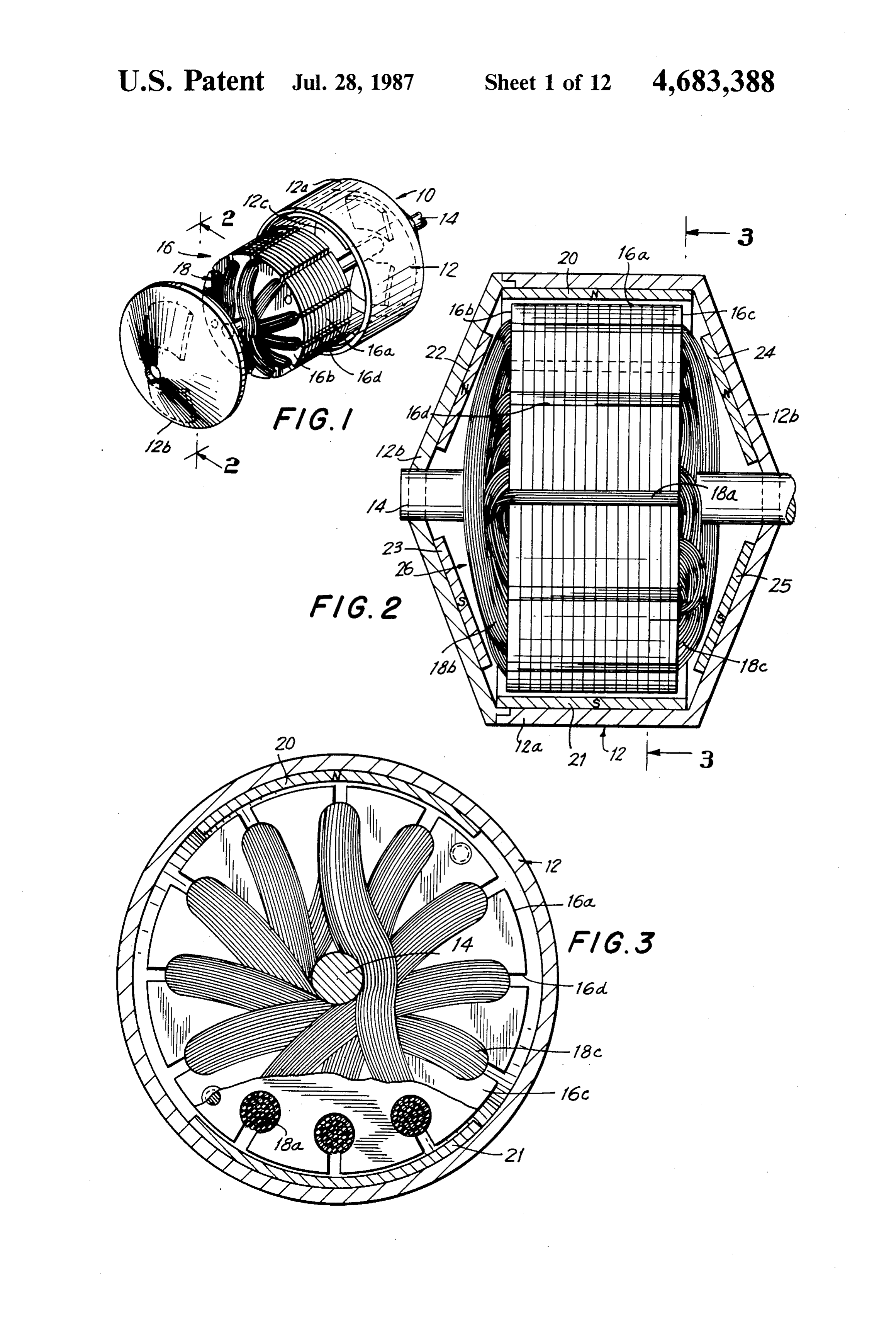
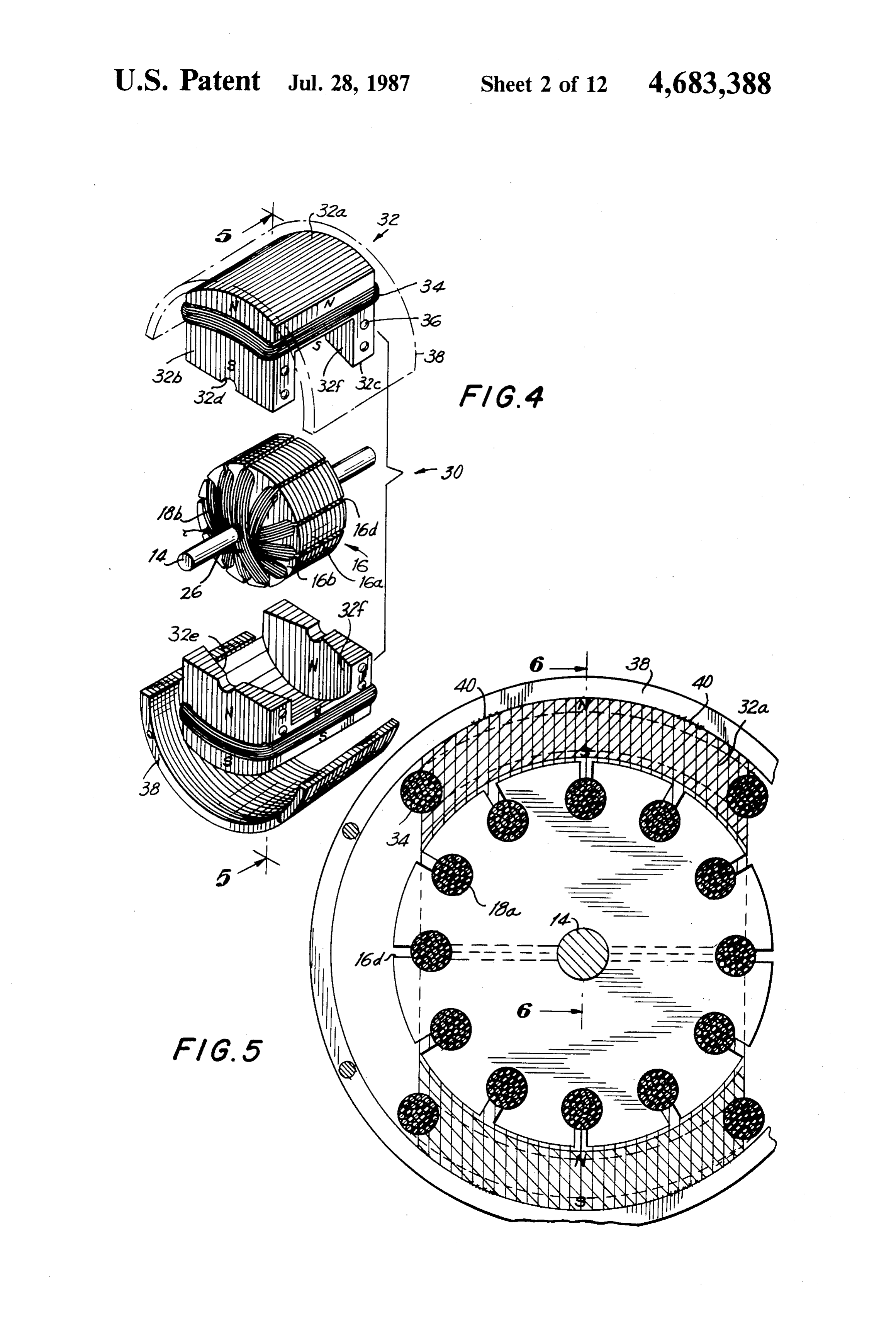
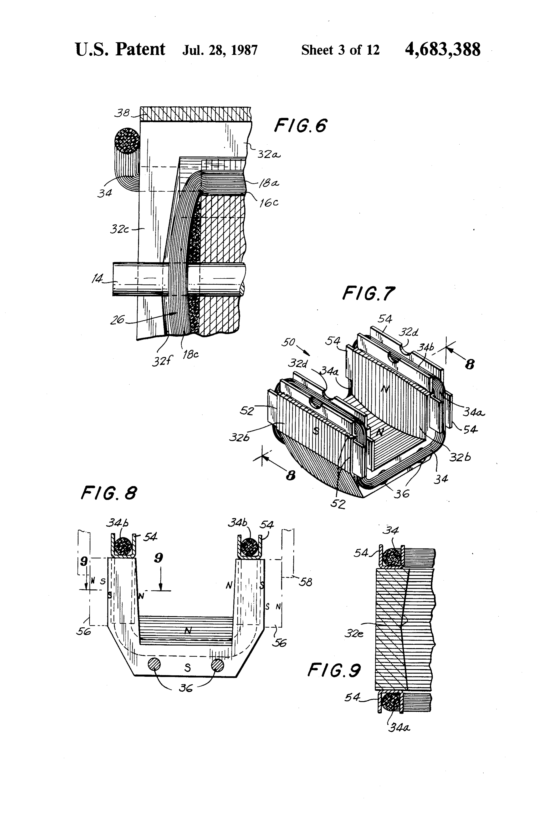
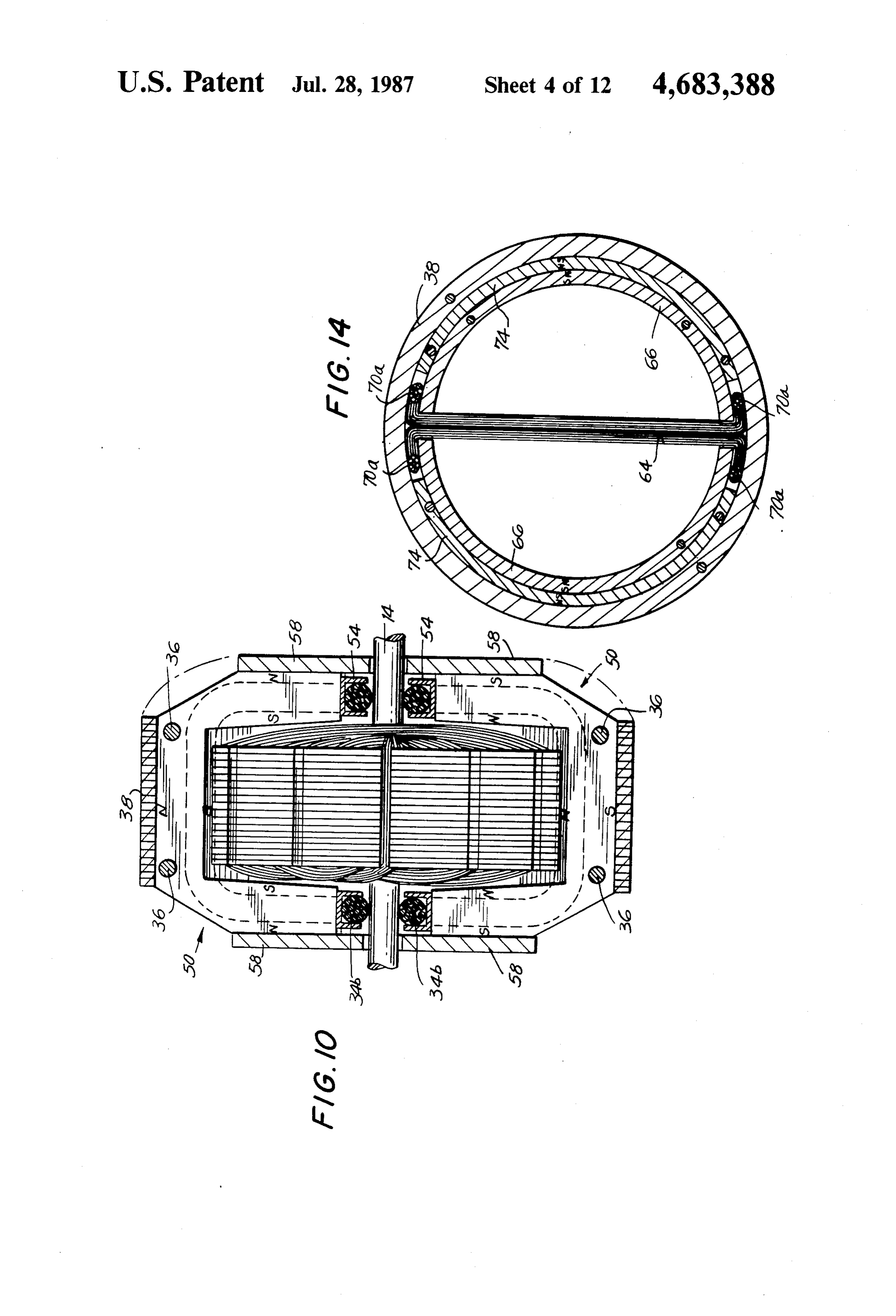
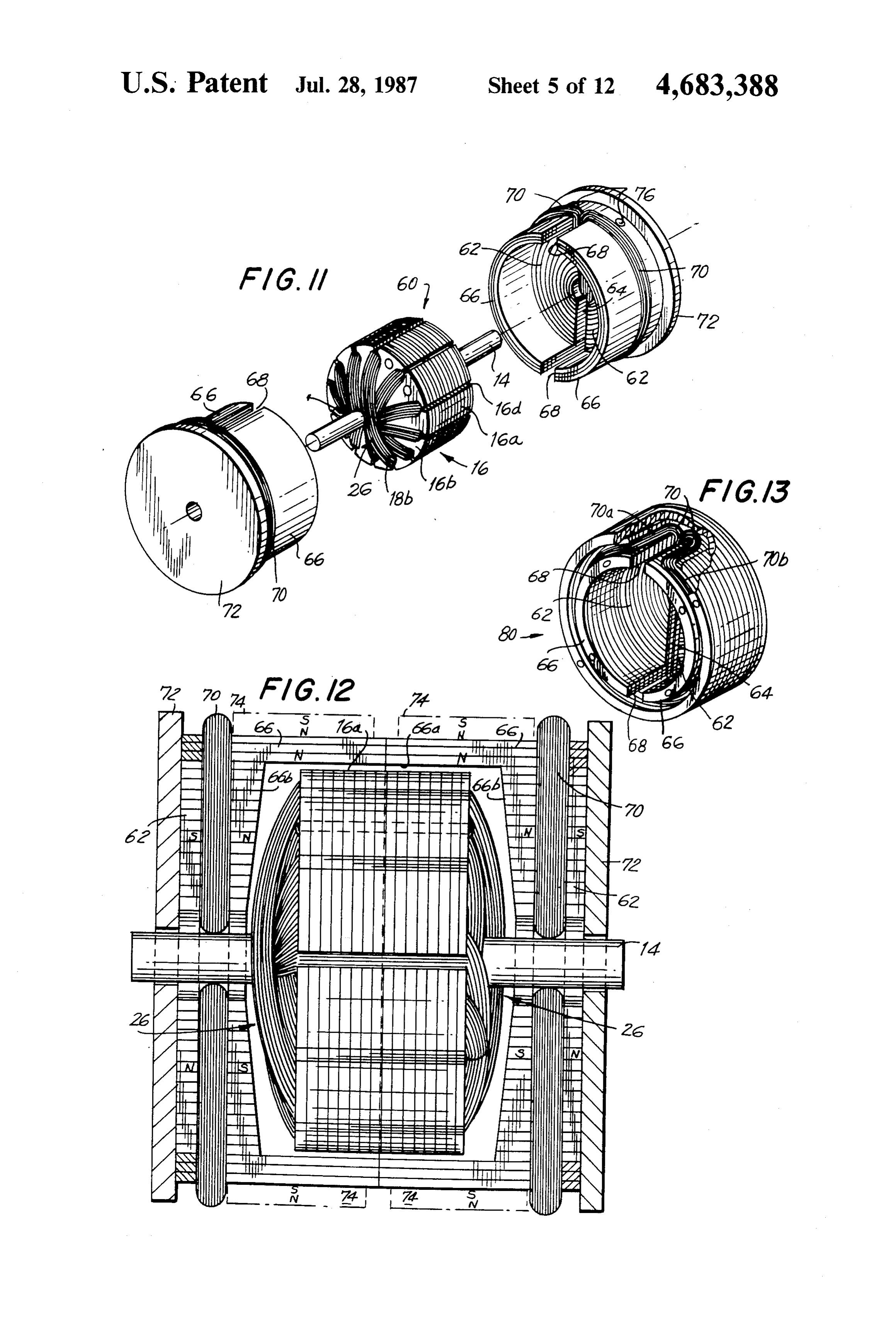
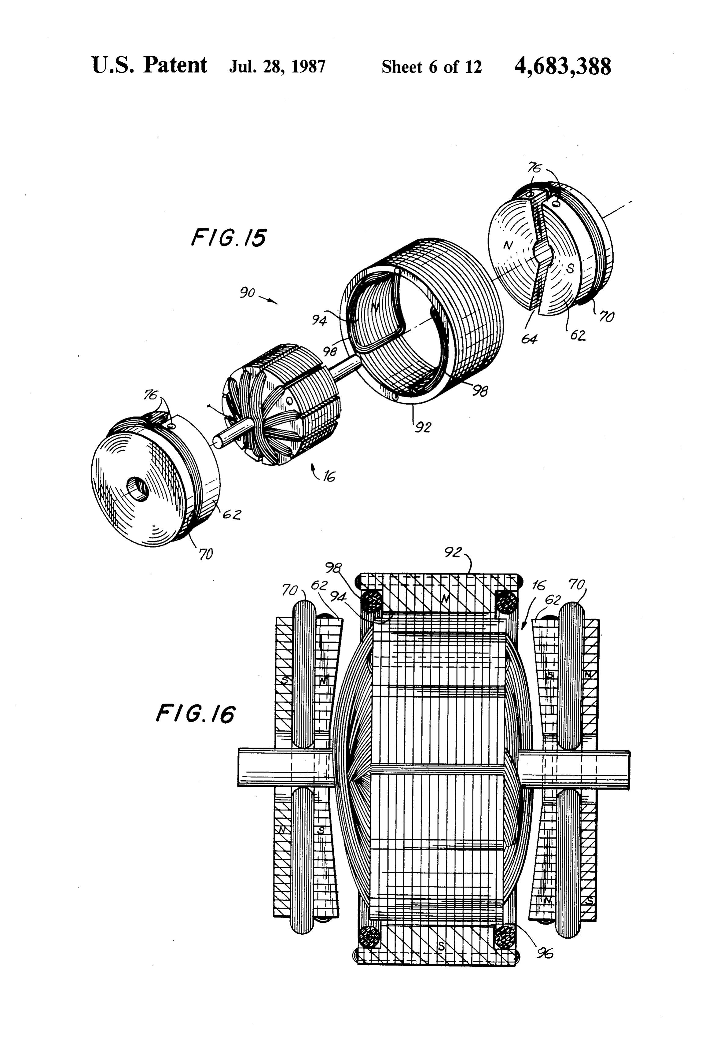
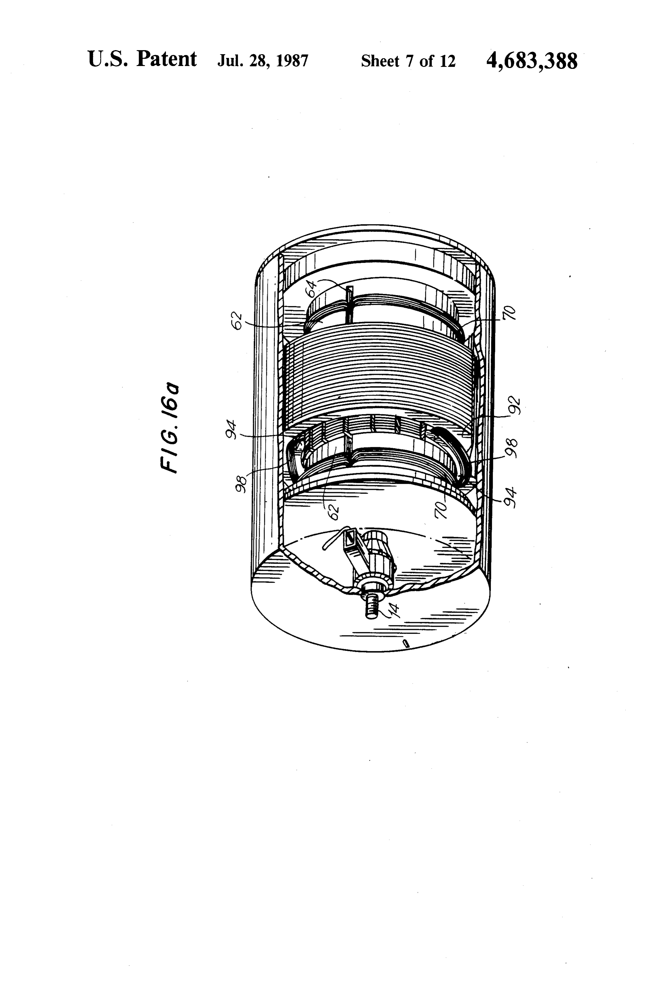
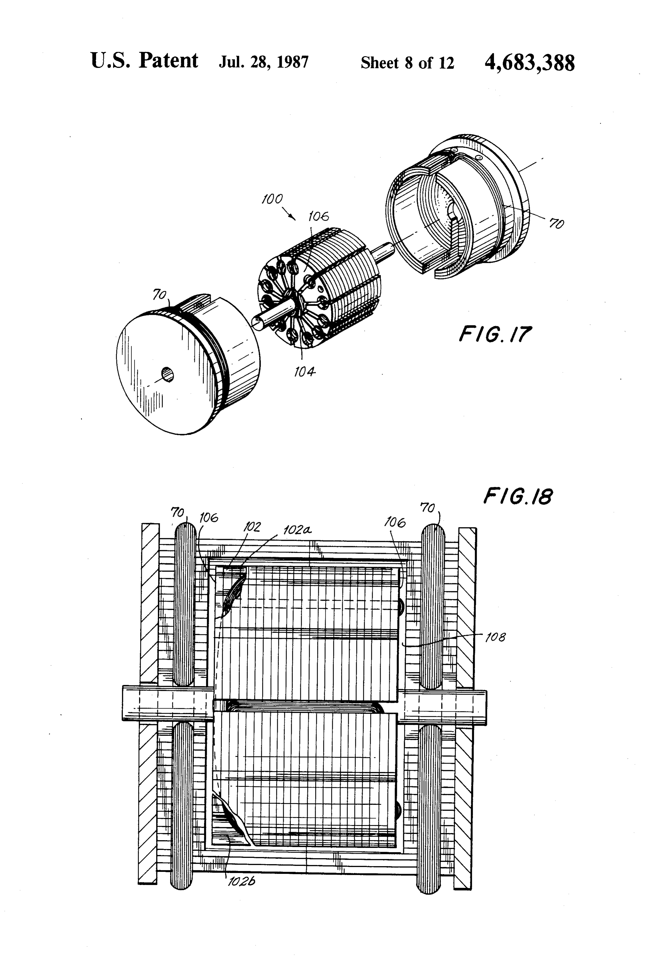
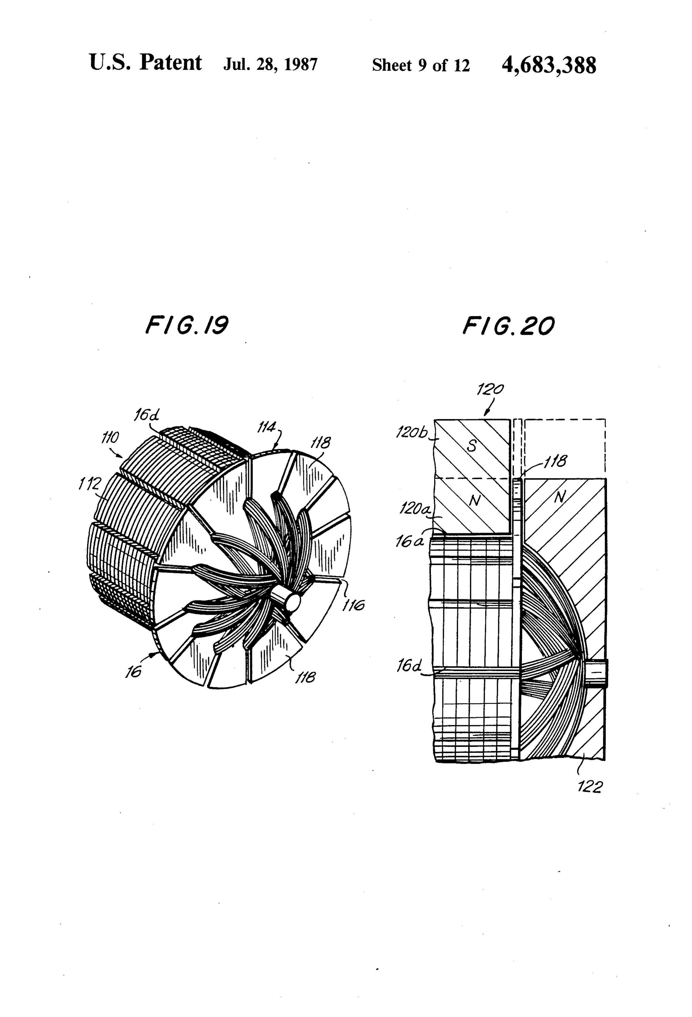
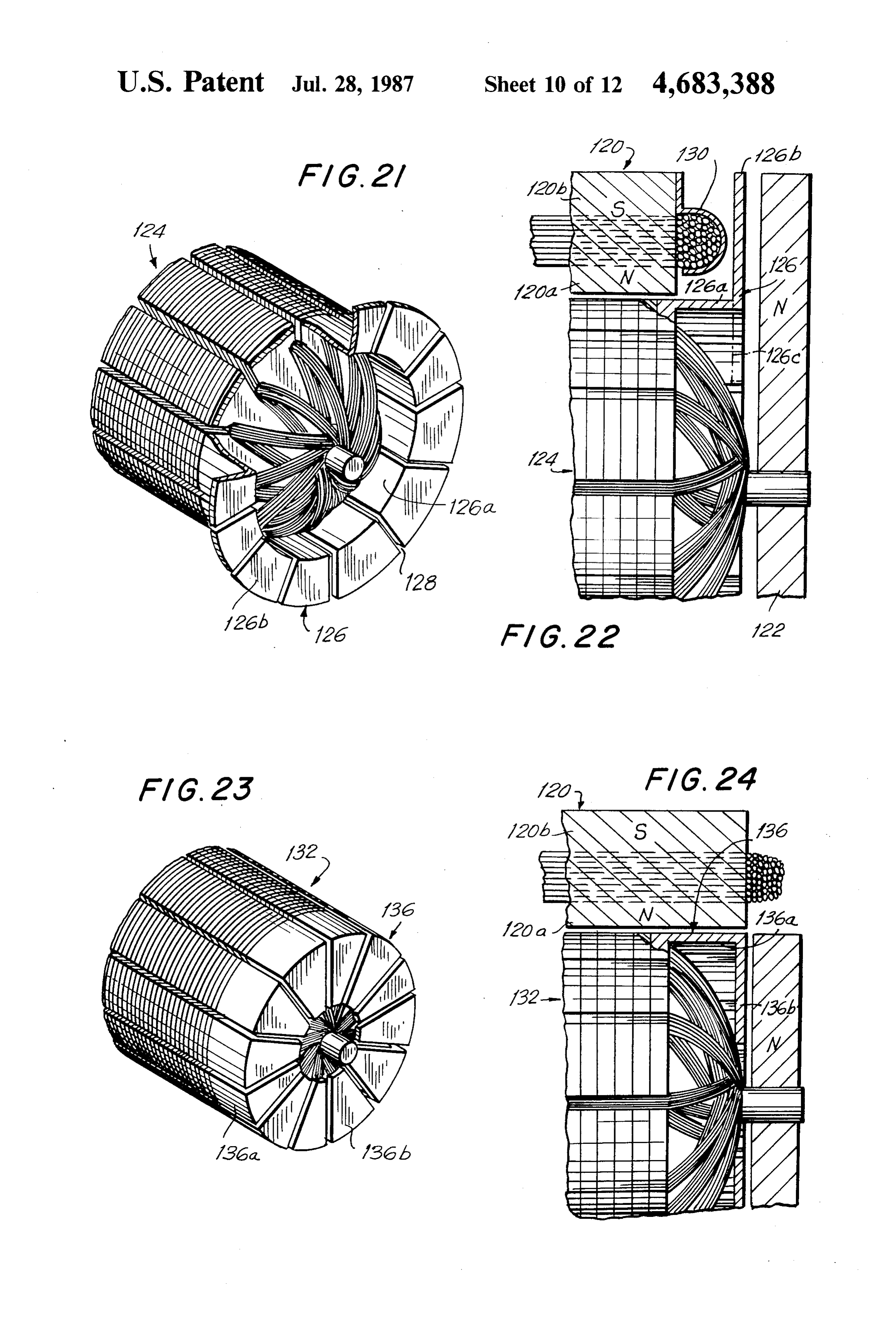
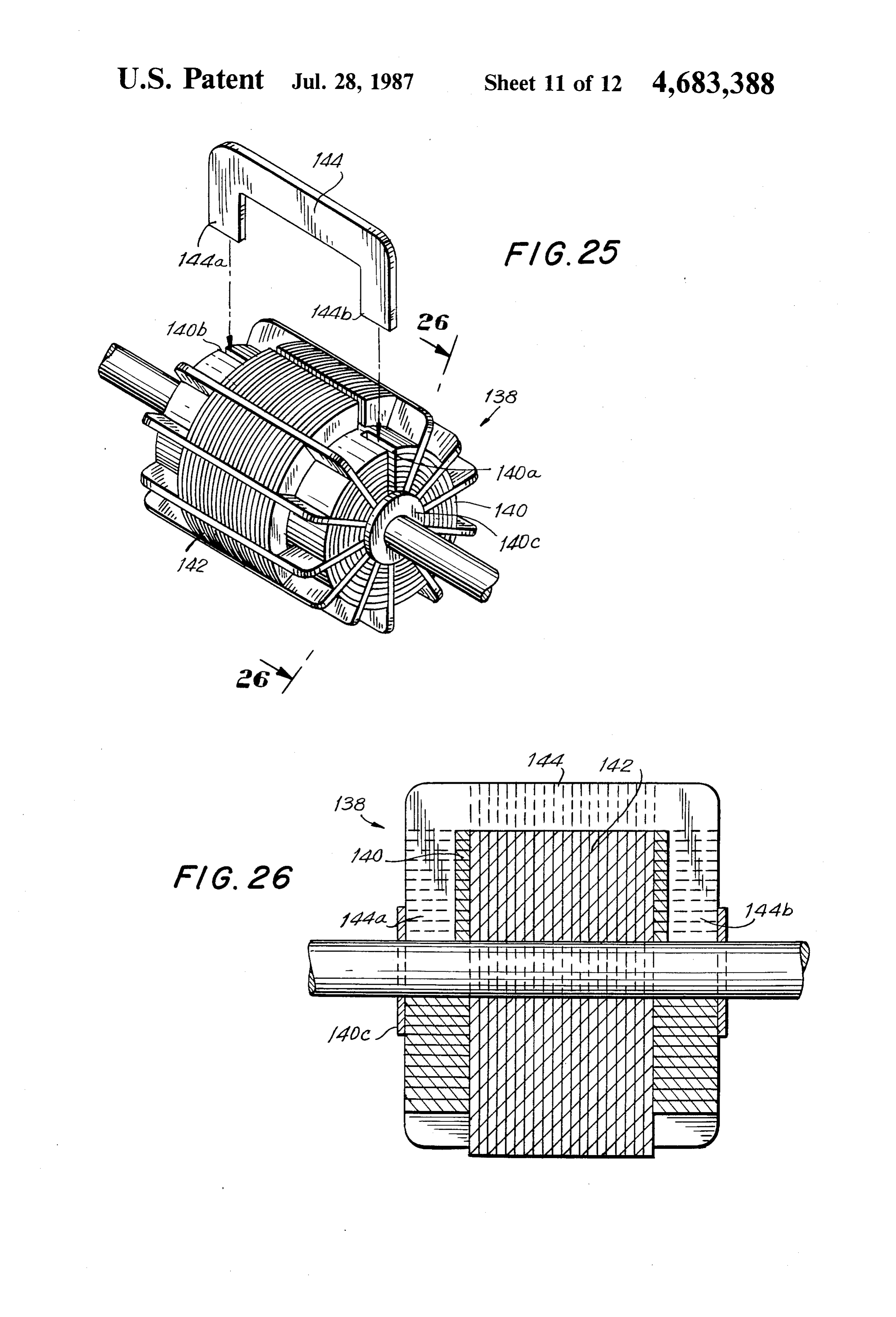
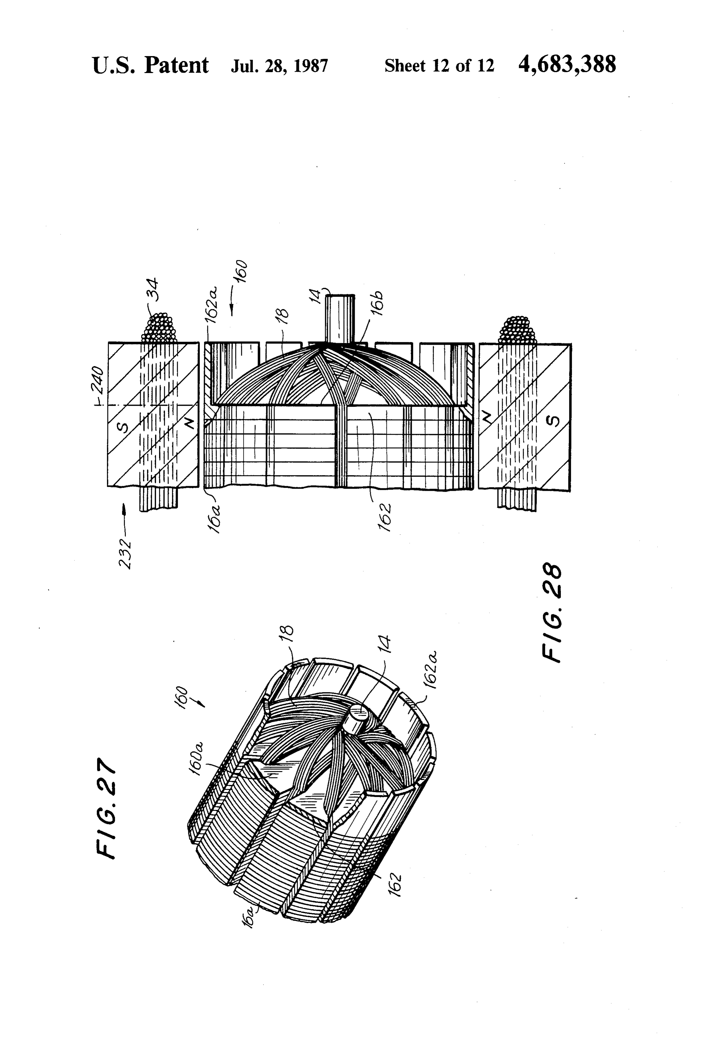
FIG. 2 is an enlarged cross-sectional view of the provide a dynamoelectric machine of the type having a assembled machine shown in FIG. 1, taken along line cylindrical rotor and which makes simultaneous use of 2-2;
FIG. 21 is similar to FIG. 19, but showing a modified What has been described up to this point is a dynamo embodiment wherein the magnetic portions are axially electric machine, either a motor or generator, which is conventional in construction.
Page 2drawing sheetscan →
Page 3drawing sheetscan →
Page 4drawing sheetscan →
Page 5drawing sheetscan →
Page 6drawing sheetscan →
Page 7drawing sheetscan →
Page 8drawing sheetscan →
Page 9drawing sheetscan →
Page 10drawing sheetscan →
Page 11drawing sheetscan →
Page 12drawing sheetscan →
Page 13drawing sheetscan →
Page 14scan →
pancake-type rotor, a flat substrate is provided on
COMPOUND INDUCTION ELECTRIC ROTATING which various winding patterns are printed. Such wind MACHINE ing patterns may be etched, plated, printed or pressure bonded on such thin discarmature of insulating material.
CROSS-REFERENCE TO RELATED 5 However, because of the difficulties which have been APPLICATION experienced with such thin disc-armatures, primarily
This is a continuation-in-part of U.S. Ser. NO. because of the flexibility of the discs on which the con 209,646, filed Nov. 24, 1980, issued as U.S. Pat. No. ductors are placed, an electric machine has been dis 4,441,043, 4/3/84 and of U.S. Ser. No. 438,905, filed 10 closed in U. S. Pat. No. 3,487,246 which applies such Nov. 1, 1982, U.S. Pat. No. 4,581,554, 4/8/86. conductive pattern on a conical surface of an insulating member. The purpose of making the armature conical is
BACKGROUND OF THE INVENTION to provide a more rigid structure than the flat disc arma 1. Field of the Invention ture structures. Such flat substrate armature machines, The present invention generally relates to dynamo however, whether flat or conical, cannot provide the electric machines capable of operating in a generator 15 mechanical or electrical power output as is possible mode or in a motor mode and, more specifically, to with conventional cylindrical rotor machines. increased efficiency compound interaction AC and/or U.S. Pat. No. 4,143,288 discloses a coreless motor DC dynamoelectric machines. which includes a rotor having a plurality of coils consti 2. Description of the Prior Art tuting a pancake coil. The motor disclosed in this patent Most armatures have distributed windings, i.e., wind 20 is a special purpose motor which is capable of being ings which are spread over a number of slots around the attached to electrical parts such as balance weights, periphery of a rotor or armature of the machine. In servo-mechanisms, etc. However, this motor likewise most conventional designs the machines are of a radial lacks the conventional cylindrical rotor found in most magnetic gap type so that electrical currents applied to dynamoelectric machines which is provided with a the windings of the rotor or stator, or to the windings of 25 distributed armature winding. As with the other pan both, generates electromagnetic fields in the rotor or in cake-type armatures, the coreless motor disclosed in the stator, as the case may be. The torque or the EMF this patent does not have a radial air gap and, therefore, induced in the machine results from the interaction does not have the ability to compound the interaction or between the magnetic field in the radial magnetic gap induction in the machine both at the axial ends and the and the generally parallel axial winding portions of the 30 armature coils disposed in the axial grooves or slots of peripheral
There surface of the armature.
has also been proposed a dynamoelectric ma the armature. However, the back and front connections chine which has plural stators. Such machines have which are those portions of the windings which connect been disclosed in U.S. Pat. Nos. 3,396,296; 3,426,224; Substantially diametrically opposing axial wire portions 3,602,749; 3,729,642 and 4,114,057. These patents, all situated in the grooves have not been utilized in order to 35 issued to the same patentee, were intended to combine enhance the efficiency of the machine. Such front and advantages of using both the radial gap and axial gap in back connections, which are substantially normal to the dynamoelectric machines. However, to do so, applicant axis of the machine, rotate with the armature but have disclosed a complicated structure making use of both not been used to increase the torque of the machine, in inner and outer stators and a hollow cylindrical rotor. the case of a motor, or to increase the power output, in In these structures, a first stator is disclosed within the the case of a generator. Specially designed special pur hollow cylindrical rotor and a second stator, also cylin pose dynamoelectric machines have been proposed in order to increase the efficiency and power output for drical in shape is disposed such as to surround the rotor. given weight and size of the machine. One approach has In this way, double radial air gaps are formed. It was been to use axial air gap type machines such as the 45 also suggested that end stators may be used to form axial brushless axial air gap inductortype dynamoelectric air gaps between the ends of the rotor and the magnetic machine disclosed in U. S. Pat. No. 3,467,844. The ma field created by the end stators. These machines were chine disclosed in the aforementioned patent uses plural described as having greater efficiency than conven variable reluctance rotors and a toroidal coil stator tional motors or generators as the result of the increased therebetween. However, the machine does not make 50 interaction between the multitude of magnetic field and use of a radial air gap. Accordingly, the machine re electromagnetic fields. However, the machines pro quires a special construction which does not make use posed in the last mentioned series of patents are uncon of conventional distributed armature-type windings. ventional in design and construction, do not have radial In an effort to provide electric machines which are grooves and do not have front and back armature wind inexpensive and small in size, there has also been devel 55 ing connections at the axial ends of the rotor as is pres oped disc-type rotors in machines defining axial air ent in the normal distributed armature winding arrange gaps. One example of such a machine is disclosed in ments. Instead, the windings are each wound around a U.S. Pat. No. 3,558,947. In that patent, a D.C. motor is flat, relatively thin magnetic core. described which includes a disc armature and a perma Other special purpose dynamoelectric machines have nent magnet stator providing an axial air gap. Such 60 been proposed for special appliations. Thus, for exam machines, which use axial air gaps and generally flat ple, in U.S. Pat. No. 4,051,401, a spherical air gap motor armatures are sometimes referred to as having a pan is disclosed wherein the magnetic ring closing the stator cake coil. Such pancake coils or rotors contain all of the magnetic loop has a non-cylindrical shape. Such elec armature turns in a generally flat plane which is normal tric motors with spherical air gaps have found applica to the shaft or axis of the machine. There is, accord 65 tions in pump drives, particularly for hermetically ingly, no axial air gap as there is in conventional cylin sealed chemical pumps.
drical rotor distributed armature winding machines. In The use of magnets at the axial ends of an armature is Some instances, instead of making use of a winding on a also known. See, for example, U.S. Pat. No. 4,237,394.
Page 15scan →
However, the last mentioned patent utilizes the end in proximity to said rotor cylindrical circumferential magnets as part of a frequency generator where the . surface, and second magnetic fields producing means magnets are used as part of a variable reluctance mag for producing second magnetic field axially beyond at netic circuit to induce a signal of a desired frequency in least one of said axial end surfaces to enhance the mag a generation coil. netic induction into said rotor, whereby the total induc The prior art has not, however, utilized both per tion of magnetic flux into said rotor is substantially the pheral and end stators in cylindrical rotor machines to additive result of both said first and second magnetic simultaneously cooperate with both rotor axial and fields.
radial coil portions to enhance the efficiency of the The present invention seeks to optimize the efficiency machine and significantly improve its performance 10 of electric machines which utilize distributed armature characteristics. By harnessing the additional torque, in windings without materially altering the construction, the case of motor operation, or the additional electro the size or the cost of such machines. The features of the magnetic inductive force, in the case of generator oper present invention can readily be incorporated into exist ation, significant improvements in efficiency can be ing more conventional designs to significantly increase obtained without compromising any constructional 15 the efficiency of such machines without sacrificing any features and without the need to resort to unconven of the features or advantages of those machines. tional, complicated or costly machine designs. BRIEF DESCRIPTION OF THE DRAWING
Summary of the invention
The objects and advantages of the present invention
Accordingly, it is an object of the present invention 20 will become apparent to those skilled in the art when to provide a dynamoelectric machine which is not pos the following description of several illustrative embodi sessed of the disadvantages associated with the afore ments of the invention is read in conjunction with the mentioned prior art machines. accompanying drawings, in which: It is another object of the present invention to pro FIG. 1 is a perspective, partially exploded view of a vide a dynamoelectric machine which is simple in con 25 dynamoelectric machine in accordance with the present struction and economical to manufacture.
It is still another object of the present invention to invention;
FIG. 2 is an enlarged cross-sectional view of the provide a dynamoelectric machine of the type having a assembled machine shown in FIG. 1, taken along line cylindrical rotor and which makes simultaneous use of 2-2;
both peripheral and end stators which cooperate with 30 FIG. 3 is a cross-sectional view of the machine shown radial and axial rotor coil portions to provide com pound interaction between the armature and multiple in FIG. FIG. 2, taken along line 3-3; 4 is an exploded view, in perspective, of another
StatOS.
It is yet another object of the present invention to dance with theofpresent embodiment a dynamoelectric machine in accor invention;
provide a dynamoelectric machine of the type sug 35 gested in the last object which has a significantly higher assembled machine shown cross-sectional FIG. 5 is an enlarged in FIG. 4, view of the taken along lines efficiency than the prior art comparable machines to thereby provide substantial improvements in output 5-5; FIG. 6 is a partial, cross-sectional view of the ma torque, in the case of motor operation, and significant chine increases in electrical output power, in the case of gen 40 FIG.shown 7 is a in FIG. 5, taken along line 6-6;
perspective view of half of a stator con erator operation.
It is a further object of the present invention to pro structed in accordance with still another embodiment of vide the features and advantages suggested in the afore theFIG. present invention.
8 is a cross-sectional view of the stator shown in mentioned objects both in A.C. or D.C. dynamoelectric machines. 45 FIG. 7, taken along line 8-8; In order to achieve the above objects, as well as oth FIG. 9 is a partial, cross-sectional view of the stator ers which will become apparent hereafter, a dynamo shown in FIG. 8, taken along line 9-9; FIG. 10 is a cross-sectional view of a dynamoelectric electric machine in accordance with the present inven machine fully assembled and making use of stators of tion comprises a frame, and a rotatable shaft supported by said frame. A cylindrical rotor is mounted coaxially 50 the type shown in FIGS. 7-9;
on said shaft, said cylindrical rotor defining two axial FIG. 11 is an exploded view, in perspective, of yet end surfaces each substantially in a plane normal to said another embodiment of the present invention; shaft and a cylindrical circumferential surface coaxial FIG. 12 is an enlarged, cross-sectional view of an with such shaft between said axial end surfaces. Said assembled machine of the type shown in FIG. 11; rotor is provided with a plurality of grooves which are 55 FIG. 13 illustrates, in perspective, a stator in accor generally parallel to said shaft and substantially uni dance with a still further embodiment of the present formly spaced from each other about said circumferen invention, wherein the stators are a modification of the tial surface to define a predetermined number of mag stators illustrated in FIGS. 11 and 12; netic poles. A distributed armature winding is provided FIG. 14 is an enlarged, cross-sectional view of the which has axial portions parallel to said shaft and re 60 stator shown in FIG. 13, taken at a cutting plane which ceived within said rotor grooves and radial portions in is normal to the axis of the stator; the region of said end surfaces and extending between FIG. 15 is an exploded view, in perspective, of yet a substantially diametrically opposite grooves with re further embodiment of the present invention; spect to said shaft. FIG. 16 is an enlarged, cross-sectional view of the An important feature of the present invention is the 65 machine shown in FIG. 15, taken at a cutting plane provision of the first magnetic field producing means which is essentially parallel to the axis of the machines; mounted on said frame for producing a first magnetic FIG. 16a is a perspective view of the assembled ma field in the region between said rotor axial end surfaces chine shown in FIGS. 15 and 16;
Page 16scan →
FIG. 17 is similar to FIG. 15, but shows yet an addi uniformly spaced from each other about the circumfer tional embodiment in accordance with the present in ential surface 16a, vention; A distributed armature winding generally indicated FIG. 18 is similar to FIG. 16 but illustrates a cross by the reference numeral 18 is provided on the rotor or sectional view of the embodiment shown in FIG. 17. 5 armature 16 in a conventional manner and having axial FIG. 19 is a fragmented perspective view of a rotor portions 18a which are parallel to the shaft 14 and re construction in accordance with the present invention ceived within the rotor grooves or slots 16d. The dis which utilizes radially outwardly extending magnetic tributed armature winding also defines radial portions portions at an axial end surface of the rotor; 18b in the region of the end surfaces 16b and 16c which FIG. 20 is an enlarged side elevational view of the 10 extend between substantially diametrically opposite rotor shown in FIG. 19, and also showing placement of grooves 16d with respect to the shaft 14. The radial stator magnets for cooperation with the magnetic por portions 18b are sometimes referred to as front winding tions, and also showing in dashed outline an optional connecting portions, while the radial portions 8c are sometimes referred to as back winding connecting por configuration having extended magnetic portions and 5 tions.
complementary-sized end stator magnets.
FIG. 21 is similar to FIG. 19, but showing a modified What has been described up to this point is a dynamo embodiment wherein the magnetic portions are axially electric machine, either a motor or generator, which is conventional in construction.
offset from the rotor; In order to better appreciate the present invention, a FIG. 22 is similar to FIG. 20, but showing the con 20 brief description of conventional dynamoelectric ma struction shown in FIG. 21; chines will now be given in relation to the structure FIG. 23 is similar to FIG. 21, but showing a further which has embodiment wherein the magnetic portions project the presentbeen state described up to this point. According to of the art, the magnetic influence of the radially inwardly instead of radially outwardly; magnetic field established by a stator magnetic circuit FIG. 24 is similar to FIG. 22, but showing the con 25 construction interacts primarily with the perimeter or struction of FIG. 23; peripheral surface 16a of the armature in order to create FIG. 25 is a perspective view of still another rotor torque or the force which produces rotation. Typically, construction in accordance with the present invention the field assembly stators are constructed with diametri wherein electrical conductors form a modified squirrel cally opposite north and south magnetic pole surfaces cage arrangement wherein end rotor portions serve as 30 conforming to armature perimeter or peripheral surface magnetic portions which couple the axial magnetic and interacts only with the axial winding portions 18a, fields to the armature; and which lie in the peripheral grooves or slots 16d. Such a FIG. 26 is an enlarged cross-sectional view of the conventional approach has been taken notwithstanding rotor shown in FIG. 25, taken along line 26-26. the fact that the front connecting or radial portions 18b FIG. 27 is a fragmented perspective view of a rotor in 35 and the back connecting or radial portions 18c have accordance with a modified embodiment of the inven necessarily existed in all rotor or armature windings tion; and substantially as suggested in the figures. Yet, there has FIG. 28 is an enlarged side elevational view of the not been any attempt to take advantage of these addi rotor shown in FIG. 27. tional winding portions, at each axial surface of the DESCRIPTION OF THE PREFERRED 40 rotor or armature, in order to enhance the efficiency of
Generally, the present invention has for its primary
Referring now more specifically to the figures, in object to construct field assembly stators which interact which identical or similar parts are designated by the with the armature coils not only along the periphery or same reference numerals throughout, and first referring 45 circumferential surface of the armature or rotor, but to FIGS. 1-3, there is shown a first presently preferred also along both axial sides of the armature. While the embodiment which utilizes permanent magnets in the description of various preferred embodiments that fol Stators. low disclose stator constructions which incorporate The permanent magnet embodiment of the dynamo both permanent magnet, electromagnetic, or combina electric machine in accordance with the present inven 50 tions of both, all constructions achieve the beneficial tion is generally designated by the reference numeral result that additional stator magnetic fields are pro 10. The machine 10 includes a generally cylindrical duced and arranged to interact with the hitherto ne frame 12 of the type normally used in conventional glected front and back connecting portions 18b and 18.c cylindrical rotor dynamoelectric machines having dis as will be more fully described hereafter. tributed armature windings. 55 Additionally, all armatures 16 are shown to be 12-coil A shaft 14 is provided which is rotatably mounted on assemblies. However, this is only for illustrative pur the frame 12 by conventional means, such as suitable poses, and, as will be more fully evident from the disclo bearings (not shown). sure that follows, any armature coil assembly can be A cylindrical rotor or armature generally indicated used while still achieving the objects of the present by the reference numeral 16 is mounted coaxially on the 60 invention. The associated 12-segment commutator as shaft 14. The cylindrical rotor 16 defines a cylindrical sembly, which will be used with the 12-coil windings circumferential surface 16a coaxial with the shaft, and shown, would normally be common to all embodi two axial end surfaces 16b and 16c each substantially in ments. However, the commutator assembly has been a plane ncrmal to the shaft 14 and disposed at each axial omitted from the illustrations in the interest of expedi end of the cylindrical circumferential surface 16a. The 65 ency and clarity since they are fully conventional. rotor or armature 16 is provided with a plurality of Motor housings, insulation and terminal wiring arrange rotor coil winding-receiving grooves or slots 16d which ments have likewise been excluded for the same reason. are generally parallel to the shaft 14 and substantially Where shown, the letters 'N' and "S' denote north and 17 south poles respectively and are included for purposes which is minimum at the circumferential surface 16a of illustration only. Clearly, the poles can be reversed in and gradually increases to a maximum in the region of most instances without any adverse effects on the oper the shaft 14. This build-up which is generally desig ation or efficiency of the machines. nated, for example, in FIG. 2 by the reference 26, de Accordingly, with each of the embodiments to be fines a generally conical convex surface. In order to described, there is provided magnetic field producing minimize the air gap between the winding radial por means mounted on the frame 12 for producing a first tions and the permanent magnets 22-25, and therefore magnetic field which bridges the radial air gap between enhance the coupling between the stator field in those the frame 12 and the cylindrical circumferential surface regions with the side or connection windings, the frame 16a which is directed to interact with the winding axial O end covers 12b are configurated to generally conform portions 18a, and second magnetic fields, in the region to the conical convex surfaces. Of course, as suggested of each axial end surface 16b, 16c of the rotor or arma previously, the same is true for the radially spaced mag ture 16, which are directed to interact with the respec nets 20 and 21 disposed on the cylindrical portion 12a of tive winding connection or radial portions 18b, 18C, the frame. By minimizing the air gaps between the per Referring again to FIGS. 1-3, the stator magnetic 15 manent magnets and the associated armature winding circuit is shown to comprise a series of permanent mag portions, coupling between the associated fields are nets having the relative polarities as shown. Thus, there optimized and magnetic interaction, whether it is to is provided diametrically opposed permanent magnets produce a torque or to generate an induced EMF, is 20 and 21, of opposite polarities. The magnetic field enhanced. In the embodiment of FIGS. 1-3, the end created between the permanent magnets 20 and 21 brid 20 covers 12b are each shown to define a generally con ges the radial air gap and interacts with the axial wind cave surface which conforms to each conical convex ing portions 18 a of the armature winding. surface defined by the radial winding portions. There The frame 12, as shown particularly in FIGS. 1 and 2, fore, in the embodiment being described, the first stator also includes stator end portions, covers or plates 12b field is produced by the permanent magnets 20 and 21 which close the respective openings formed at each 25 while the second magnetic fields, which are produced axial end of the cylindrical portion 12a of the frame 12. as the result of the use of the constructions in accor While one of the covers or plates 12b may be integrally dance with the present invention, are created by the formed with the cylindrical frame portion 12a, the other permanent magnets 22 and 23, at one axial end, and the cover 12b must, of course, be necessarily removable to permanent magnets 24 and 25 at the other axial end. allow insertion of the rotor or armature 16 into the 30 It has been found that the inclusion of the additional frame 12. permanent magnets 22-25 can more than double the Mounted on one frame end cover 12b, on diametri torque output from the machine without an increase in cally opposite sides of the shaft 14, are permanent mag the current requirement for the armature coils. Addi nets 22 and 23 of opposite polarity as shown. Similarly, tionally, a much greater EMF could be induced permanent magnets 24 and 25, also of opposite polarity, 35 thereby. The magnitudes of the aforementioned im are disposed on diametrically opposite sides of the shaft provements results are equally applicable to all of the 14 on the other of the end frame covers 12b. As should electromagnetic configurations which will be described be evident, providing permanent magnets of opposite below.
polarities on diametrically opposite sides of the shaft 14 It should also be pointed out with respect to the em on each of the frame covers 12b creates a magnetic field 40 bodiment of FIGS. 1-3 that while all the stator fields in which couples to the front and back connection or the this embodiment are produced by permanent magnets, radial portions 18b and 18c to thereby interact there same or similar results can be obtained where at with. The machine allows for a significant improvement least one of these permanent magnets is replaced by an in efficiency over the conventional perimeter-only sta appropriate electromagnet which displays or exhibits tor embodiments. Since the embodiment of FIGS. 1-3, 45 the same polarities. Therefore, in the embodiment of as well as the other embodiments to be described hereaf FIGS. 1-3, at least one of the permanent magnets ter, permits interaction with a previously untapped shown can be replaced by an electromagnet, so that all energy field, i.e. the axial sides of the armature coils, the of the stator field producing means will be either perma machine, when operating in a motor mode, will func nent magnets, electromagnets or combinations thereof. tion to produce a given amount of torque at the shaft 50 Referring to FIGS. 4-6, there is shown another pres utilizing only a small fraction of the normally required ently preferred embodiment of the present invention current or input electrical power. Stated otherwise, for which is in the nature of a single stator embodiment the same amount of input electrical power, a machine designed to use only two coils in the stator creating only operating as a motor and incorporating the subject in one north and one south pole. The second embodiment vention will produce significantly more output torque 55 is generally designated by the reference numeral 30. at the shaft 14. Corresponding efficiencies would, of The armature 16 is identical to the one previously de course, result if the machine were to be used in a gener scribed in connection with the first embodiment of ator mode. FIGS. 1-3. Here, however, the magnetic field produc In order to take full advantage of this additional ing means includes two opposing generally U-shaped source of interaction between the armature or rotor and 60 magnetic cup members 32 disposed in diametrically the stator fields and, therefore, to optimize upon the opposite sides of the rotor 16 to substantially surround efficiency which may be obtained thereby, the configu the same. Each cup member 32 has a longitudinal por ration of the stator field is modified, where appropriate, tion 32a generally conforming to the shape of the rotor to enhance coupling between the stator field and the circumferential portion 16a and transverse portions 32b connection or radial portions 18b, 18C of the armature 65 and 32c, respectively at each end of the longitudinal winding. Thus, it will be noted that the winding radial portion 32a. Each transverse portion 32b, 32c extends portions 18b and 18c at each axial end surface 16b, 16c of from the associated longitudinal portion 32a to the re the rotor 16 create a build-up of overlapping windings gion of the shaft 14, the corresponding transverse por 18 tions on the opposing cup members forming air gaps circumferential surface 16a of the rotor, as well as in the therebetween proximate to the winding axial or connec axial air gaps produced in the regions of the shaft proxi tion portions 18b, 18C. A stator winding 34 is provided mate to the connection or radial winding portions 18b, which extends about each cup member 32 and disposed 18c of the armature. In a practical embodiment, the between the radially outermost and innermost surfaces yoke 38 may be joined or connected to the U-shaped thereof as shown. Advantageously, each cup member magnetic cup members in any conventional manner winding 34 extends about a respective longitudinal por such as, for example, spot welds 40 which are suggested tion 32a and is generally parallel to the shaft 14. in FIG. 5.
Circular recesses 32d are provided in each transverse While the cup members shown in FIGS. 4-6 are portion as shown dimensioned to receive the shaft 14 10 formed of stacked laminations disposed on planes paral while establishing an air gap between opposing trans lel to the shaft, the yoke 38 is, for practical reasons, verse portions on each side of the shaft. shown being formed of stacked laminations disposed in The relative polarities of the U-shaped magnetic cup planes normal to the shaft 14.
members are shown in FIGS. 4 and 5. As will be clear, A modified version of the embodiment shown in there will be a magnetic field created across the air gap 15 FIGS. 4-6 is shown in FIGS. 7-10 and the stator of this at each pair of opposing poles at diametrically opposite modified embodiment is generally identified by the sides of the shaft, that magnetic field being in a position reference numeral 50. Here, the windings 34 extend to couple again to the connection or radial portions 18b, along the outer peripheral surfaces 52 of the transverse 18c of the armature winding. Again, therefore, coupling portions 32b in a plane normal to the shaft 14, in addi with such hitherto unused armature winding portions is 20 tion to extending along the longitudinal portion as with provided to thereby enhance the overall efficiency and the embodiment shown in FIGS. 4-6. In order to main operation of the machine. tain the winding 34 in the configuration shown and in As with the first described embodiment, the cup association with the magnetic cup member, there are members 32 are advantageously provided with surfaces advantageously provided winding retainers 54 which 32e and 32f which are somewhat conical in shape and 25 are in the nature of channels having a U-shaped cross which conform as closely as practical with the gener sectional configuration. The middle retainer on each ally convex surface of the build-up 26 at each axial end transverse portion 32b is provided with a cut-out 32d of the armature. As previously suggested, such confor for receiving the shaft as previously described. mance of the stator magnetic producing field elements Referring to FIG. 10, there is shown an electrody minimize the air gaps in the axial or end regions, opti 30 namic machine incorporating two yokes 50 of the type mize coupling and, therefore, optimize interaction and shown in FIGS. 7 and 8, and the relative polarities of output. the U-shaped magnetic cup members when currents are Because the embodiment shown in FIGS. 4-6 pro caused to flow in the windings 34. In order to optimize vides the U-shaped magnetic cup members 32 which the useful flux in the machine, yokes 58 are advanta completely surround the armature to interact with the 35 geously used at each axial end of the machine to mag armature coils on all surfaces as described, the embodi netically connect the axially outermost surfaces of the ment is considered to be preferred since it will provide transverse portions, in addition to the cylindrical yoke the most torque power proportionate to its current 38 which is coaxial with the shaft 14 and encloses the requirements. In this design, the primary interaction cup members while magnetically connecting the radi thrust for motor action (or inductive thrust for genera 40 ally outermost surfaces of the longrtudinal portions as tor action) occurs at the perimeter portions of the arma described in connection with FIGS. 4 and 5. While the ture coils, which are parallel to the stator coils, as with magnetic yokes 38 and 58 are advantageously used conventional machines. However, secondary thrust or simultaneously as shown in FIG. 10, it is possible to inductive efficiency occurs at the axial side portions of eliminate one of these yokes with attendant decreases in the armature coils. Both actions are simultaneous and 45 improved results.
combine to apply greater magnetic force to the arma While the cup members shown in FIGS. 7-10 and ture coils for either motor or generator action, as appli yokes 58 are formed of laminations disposed in planes cable. parallel to the shaft 14, the laminations of the yoke 38 Still referring to FIGS. 4-6, the cup members 32 are are, as previously suggested, concentric with the axis of shown to be formed of stacked laminations disposed in 50 the shaft 14.
planes parallel to the shaft 14 and held together, for It is possible, in connection with the stators 50 of example, with rivets 36. However, any other conven FIGS. 7-10 to enhance the useful magnetic flux in the tional means for connecting the stacked laminations radial as well as axial air gaps by adding permanent may be used. magnets and, thereby, effectively form compound mag In order to optimize the magnetic fields at the axial 55 nets. Referring to FIG. 8, there is shown, by way of air gaps formed between adjacent and opposing trans example only, the addition of permanent magnets 56 verse portions 32b, there is advantageously provided a having relative polarities as shown, these enhancing the cylindrical yoke 38 which is coaxial with the shaft 14 useful stator magnetic fields by compounding the fields and encloses the cup members 32 while magnetically created by the electromagnets formed by the use of the connecting the radially outermost surfaces of the longi 60 windings 34. Such permanent magnets 56, therefore, are tudinal portions 32a of the cup members 32. As is best arranged on the axially outermost surfaces of the trans seen in FIG. 5, the use of such magnetic yoke 38, by verse portions 32b and are arranged to enhance the magnetically shorting the outermost poles, which do second magnetic fields which couple with the connec not enter into the production of useful magnetic flux, tion or radial portions 18b and 18c of the armature. reduces the reluctance of the magnetic circuit in such a 65 As with the previously discussed embodiments, the way as to enhance or increase the magnetic flux avail internal surfaces of the stators 50 which face or are able in the various air gaps, including the radial air gaps disposed proximate to the armature are configurated to between the longitudinal portion 32a and the cylindrical minimize the air gaps therebetween and therefore opti 19 mize magnetic coupling. The conforming of the shape windings 70 in FIG. 13, therefore, include portions of the stator to the convex shape of the armature wind extending along the diametrical air gaps 64 as best ings is illustrated in FIG. 9, wherein the internal surface shown in FIG. 14, axial portions 70a extending along 32e is in the nature of a conical concave surface which the outer surface of an associated extension 66 in a di is configurated to complement the external or convex rection parallel to the shaft 14, and a circumferential shape of the armature end windings 18b, 18c. winding portion 70b which extends along the circum Referring to FIGS. 11 and 12, there is shown a fur ferential outer surface of an associated extension 66 in a ther embodiment of the present invention which is gen plane substantially perpendicular to the shaft 14. With erally designated by the reference numeral 60. As be this modified embodiment 80, as best shown in FIG. 14, fore, the rotor or armature is substantially the same as there is advantageously provided a cylindrical yoke 38 previously described. In this embodiment, however, the coaxial with the shaft 14 and magnetically connected stator magnetic field producing means includes two with the radially outermost surfaces of the semicylindri members which may be semicircular, magnetic sectors cal projections 66.
62 at each axial end of the rotor 16, arranged to form a In accordance with another feature of the embodi diametrical air gap 64 proximate to the winding radial 15 ment shown in FIGS. 13 and 14, the yoke which is in portions 18b, 18C. Each sector 62 has associated there the nature of the circular disc 72 may be magnetically with a semi-cylindrical projection 66 dimensioned to connected to the axially outermost surfaces of the mag cover in close proximity a portion of the rotor circum netic sector 62, so that where the cylindrical yoke 38 is ferential surface 16a. The semi-cylindrical projections used, the circular disc and cylindrical yokes are joined 66 on associated sectors 62 also form longitudinal air 20 together to form a continuous yoke which encloses the gaps 68 which are parallel to the shaft 14 and proximate respective set of sectors and associated projections. to the winding axial portions 18a. A winding 70 is pro The embodiments described above and shown in vided which extends about the peripheries of the sectors FIGS. 11-14, 16 and 18 can be described as having dual 62 in a plane substantially normal to the shaft 14. In this disc stators designed to use a total of 4 stator coils, each manner, the windings 70 create a field at the diametrical 25 set of stator poles being created by two coils. As with air gaps 64 suitable for coupling to the radial winding or the other embodiments previously described, each sta connection portions 18b, 18C and at the longitudinal air tor disc surrounds the armature 16 and permits interac gaps 68 for coupling to the axial winding portions 18a. tion with the armature coils at all surface portions The relative polarities for an illustrative arrangement thereof, including the circumferential and end surfaces. and directions of winding currents are illustrated in 30 These designs provide greater torque power than the FIG. 12. In order to enhance the useful magnetic stator single stator embodiment illustrated in FIGS. 4-10. In flux, there are advantageously provided yokes, such as the embodiments of FIGS. 11-14, 17 and 18, the interac 72 which are in the nature of a circular disc magneti tion between the stator fields and the armature wind cally connecting the axially outermost surfaces of the ings, whether it be to create a thrust or torque or induce magnetic sectors 62. 35 a voltage in these windings, are reversed. The main While the sectors 62 are shown formed of concentric thrust occurs at the axial side portion of the armature laminations coaxial with the shaft 14 and slotted to coils parallel to the stator poles while the secondary provide the diametrical air gaps 64, the sector 62 may thrust or inductive interaction is at the perimeter pole also be formed of a continuous spiral lamination slotted extensions parallel to the perimeter portion of the arma to provide the diametrical air gaps. The concentric and 40 ture coils. Again, both actions are simultaneous and spiral lamination approaches each have their own ad combine to apply greater magnetic force on the arma vantages and disadvantages insofar as connection, man ture coils for motor or generator action, as applicable. ufacturing economies, etc., and one may prove to be Still referring to FIGS. 11-14, 17 and 18, and particu more advantageous than the other in a given applica larly FIG. 12, it should be pointed out that when slots tlon. 45 or diametrical air gaps 64 are formed within the concen Compounding of magnets is also possible with the tric or spiral laminations forming the semicircular sec embodiment shown in FIGS. 11 and 12. By way of tor 62, the axially outer portions of the sectors 62, be example, permanent magnets 74 are shown arranged on tween the windings 70 and the disc yokes 72 also com the radially outermost surfaces of the semi-cylindrical prises, for all practical purposes, a yoke for linkage of projections 66 to enhance the useful stator magnetic 50 both poles. Accordingly, the disc yokes 72 are, in effect, fields. Whether the additional permanent magnets 74 supplemental yokes which assist in linking the poles, for are used or not, it is advantageous to make use of the example the south poles at the top of FIG. 12 and the yoke 72 which, as described, is in the nature of a circu north poles at the bottom of FIG. 12. lar disc magnetically connecting the axially outermost As with the other embodiments, concave inner sur surfaces of the magnetic sectors 62. However, because 55 faces 62b and 66b are provided for the same reasons set of the relative polarities of the magnets, it is not useful forth with regard to the other embodiments. to make use of a cylindrical type yoke of the type de Compounding of magnets is possible here too by scribed in connection with, for example, FIGS. 4 and providing magnets 74 having relative polarities as 10, and which were identified by the reference numeral shown in FIG. 12.
38. Any conventional means may be used to join the
A modified version of the electrodynamic machine concentric laminations forming the semicircular sectors shown in FIGS. 11 and 12 is illustrated in FIGS. 13 and 62, rivets 76 being shown as one possible way of accom 14. Here, as with the embodiment shown, for example, plishing this.
in FIG. 7, the modified embodiment, which is generally A triple stator electromagnetic embodiment is shown designated by the reference numeral 80, provides for 65 in FIGS. 15 and 16 and generally designated by the each winding 70 to extend about a sector 62 and also reference numeral 90. As with the last mentioned em extend along the periphery of the radially outer surface bodiment, the machine 90 comprises two semicircular of an associated extension 66 as shown in FIG. 13. The magnetic sectors 62 at each axial end of the rotor 16, 20 and a winding 70 extending about the peripheries of the the rotor 16. In this manner, the rotor 16 can be re sectors 62 in a plane substantially normal to the shaft 14 ceived within a frame 12 having a cylindrical cavity and forming a diametric air gap 64 proximate to the 108, the radial as well as axial air gaps now being capa winding radial portions 18b, 18c. A cylindrical magnetic ble of being minimized without danger of damage to the member 92 is provided which is generally coaxial with winding radial portions 18b, 18c. the shaft 14 and encloses the rotor 16 circumferential The construction of the projections 102 is not critical surface 16a. The magnetic member 92 has pole sections as long as these projections are made of a magnetic 94, 96 projecting radially inwardly into proximity to the material. Thus, as shown in FIG. 17 and the top of FIG. rotor 16 circumferential surface 16a. Windings 98 are 18, the rotor 16 and the projections 102a may be formed provided which extend about each of the pole sections 10 of stacked laminations disposed in planes normal to the 94, 96 as shown. shaft. However, as suggested at the bottom of FIG. 18, The machine 90, therefore, employs one conventional the rotor 16 may be formed of stacked laminations dis two-pole stator positioned at the perimeter surface of posed in planes normal to the shaft 14, while the projec the armature and dual two-pole disc stators previously tions 102b are formed of stacked concentric laminations described in connection with embodiments 11 and 12. 15 which are coaxial with the shaft 14 or spiral. The two Accordingly, the arrangement of the machine 90 pro different constructions have varying degrees of advan vide a total of 6 stator coils, two of these coils each tage, and the one used most be selected on the basis of producing one of the stator fields. Again, as with the the application intended. What should be pointed out is other embodiments, the three stators surround the ar that the addition of the projections 102 essentially de mature to permit interaction with the armature coils on 20 crease the reluctance at the axial air gaps, therefore all surfaces. This design will provide the greatest torque enhancing the field in those air gaps. The use of such power (or voltage induction for generator action). In additional metal to surround the build-up 26 results in this embodiment, all three stators simultaneously inter increased coupling to such connection or radial por act with all armature coil surfaces and combine to pro tions 18b, 18c with increased efficiency of the overall duce the greatest amount of torque. It may be addition 25 machine.
ally noted in connection with this embodiment that While the machine 100 shown in FIGS. 17 and 18, when used with D.C. current only, it will permit combi using the modified rotor described, has been shown nation use of permanent and electromagnets, i.e. perim used with the semicircular sectors 62 and semi-cylindri eter electromagnets and axial side or end permanent cal projections 66 of the type shown in FIGS. 11 and 12 magnets, or vice versa. 30 it should be clear that this modified rotor can be used in The disc stators shown in FIGS. 15, 16 and 16a may connection with any of the aforementioned embodi be constructed in the same manner as previously de ments in which case the end stators need not be pro scribed for the dual stator embodiment except, of vided with the modified complemental concave sur course, for the provision of the pole extensions 66. Con faces shown in the various figures. Whichever the em cave inner surfaces on the semicircular sectors are pro 35 bodiment used, once the modified rotor of FIGS. 17 and vided for the same reasons previously described. These 18 is used, the stator can be configurated to provide a stators can also be constructed of one continuous band perfectly cylindrical cavity in which the various operat coil to create a laminated core of desired diameter, as ing air gaps can be minimized without danger of dam previously suggested. A properly sized hole may be age to the armature windings.
drilled through the center close to the inner surface to 40 While all of the aforementioned embodiments shown accommodate the size and specified number of turns of in 1-18 have been for a construction for increasing the wire. A slot is then cut along the length of the drilled inductance and the coupling of lateral or end magnetic hole to form the poles and permit insertion of the coils. fields with the armature, FIGS. 19-26 illustrate an ap The back or outer side remains whole and uncut and proach which is intended to accomplish the same or comprises a yoke for linkage of both outer poles as 45 similar function but in a more efficient manner. In discussed in connection with FIG. 12. FIGS. 1-18, the side or axial end stators are designed While most dynamoelectric machines which are pro and disposed to cooperate with the end or axial rotor vided with cylindrical rotors and distributed armature winding portions. In the embodiments of FIGS. 19-26, windings on said rotors will almost of necessity result in a more direct and more efficient approach is used for a build-up of overlapping windings at the axial end 50 coupling or inducing the side or end stator magnetic surfaces of the rotor, FIGS. 17 and 18 illustrate a modi field with the armature. Referring first of FIGS. 19 and fication of all of the previous embodiments which seek 20, a modified rotor construction in accordance with to compensate for that build-up 26 in a manner other the present invention is designated by the reference than providing complementary concave surfaces on the numeral 110. As described previously, the rotor 16 is facing stator surfaces. In the last embodiment to be 55 provided with angularly spaced axial grooves 16d described, which is generally identified by the reference which define poles 112. A disc 114, made of a magnetic numeral 100 in FIGS. 17 and 18, the winding radial material, is affixed to an axial end surface of the rotor 16 portions 18b and 18c at each axial end surface of the and provided with radial slots angularly spaced about rotor 16 create a build-up 26 of overlapping windings as the axis of the rotor. The slots 116 are aligned with the previously discussed. However, while such build-up 60 grooves 16d to define magnetic portions 118, each form generally defines a conical convex surface, the modified ing an integral part of its associated pole 112 of the rotor embodiment 100 includes magnetic projections 102 16. The diameter of the disc 114 is greater than the extending axially from each end surface 16b and 16c of diameter of the rotor 16 so that the magnetic portions the rotor 16 as shown. The axial projections 102 are 118 are shown to extend radially outwardly from the configurated to extend beyond the axially outermost 65 rotor. Magnetic portions for purposes of this application points of the build-ups 26 and form protective slots 104 are intended to include all such portions or extensions for the winding radial portions 18b, 18c and further which are made of a magnetizable material, such as form a substantially flat surface 106 at each axial end of ferrous metals. The disc 114 and, therefore, the mag 21 netic portions 118 are connected and form part of the scribed in connection with FIGS. 19 and 20. However, magnetic circuit of the rotor 16. Thus, the disc 114 will the magnetic portions 126 each include an axially ex normally comprise the end rotor lamination. It is also tending portion 126a and a radially extending portion possible, however, to attach separate magnetic portions 126b which is perpendicular to the portion 126a. As 118 to the rotor structure and achieve the same or simi with the embodiment of FIGS. 19 and 20, the magnetic lar results. portions extend substantially from the circumferential This configuration 110 is designed primarily for cou surface 16a of the rotor 16. However, in FIGS. 21 and pling of radial sections of armature coil circuits to sepa 22, the portions 126b which extend radially outwardly rate conforming end stator magnetic fields, either con are offset or spaced axially from the main part of the cave or ring, in permanent magnet stator machines. 10 rotor by the portions 126a. The embodiment shown in However, it also possesses an additional advantage in FIGS. 21 and 22 is suitable for use in the three stator that it can still permit a moderate degree of lateral arma wire wound embodiment since the offset feature is de ture coupling to existing stator magnetic fields without signed to permit unobstructed armature rotation past the use of separate end stators. This phenonomen is the coil portions at the sides of the periphery stator achieved in the following manner. 15 poles.
Referring to FIG. 20, a permanent magnet periphery Shown in dashed outline are optional portions 126c stator 120 is shown which exhibits a radially innermost which project radially inwardly from the portions 126a. portion 120a which is one of polarity and a radially Thus, it is possible to utilize both extensions 126b and outermost portion 120b which exhibits the opposite 126c to still further increase the inductive characteris polarity. The diameter of the disc 114 must be such that tics. With respect to the use of this armature configura the magnetic portions 118 only extend to overlap or be tion, including the optional use of (1) only the magnetic in proximate relationship with the radially innermost portions 126b or (2) the combined use of 126b and 126c, polarity portion 120a, When the magnetic portions ex the end stator magnet 122 (permanent magnet or wire tend beyond the point indicated, the magnetic flux im wound) would be used to interact with the magnetic pact is to an extent neutralized since both poles act 25 portions 126b and 126c as applicable. simultaneously on the same armature extension or mag Also shown in FIG. 22 is a protective member 130 netic portion 118. In this embodiment additional induc of which is in the nature of a rigid protective cover made tance is obtained from the interaction of the magnetic non-ferrous material which serves as a shield for the portion 118 with the sides or axial end surfaces of the stator structure 120 when the same is in the nature of a permanent magnet portion 120a. The surface of the 30 wire-wound electromagnetic coil. Such cover 130 in magnet portion 120a which is opposite the magnetic sures that the side coil portions are protected from pos portion 118 is of the same polarity as the surface of the sible contact with the rotating magnetic portions 126 periphery stator magnet 120 which interacts directly and also permit construction of precise clearance be with the armature. tween the side coil portions and the rotating extensions Also shown in FIG. 20 is a side or end permanent 35 or portions 126.
magnet stator 122 which is likewise intended to act In FIGS. 23 and 24, there is shown a configuration of upon the magnetic portion 118. When this armature an improved rotor which is designated by the reference configuration is used to cooperate with separate con numeral 132. The rotor 132 perhaps represents the most forming end stator 122, as it is primarily intended to do, versatile configuration and is suitable for use in any of as shown, the length of the magnetic portions 118 may 40 the aforementioned stator embodiments. Here, the mag be increased for optimum inductive capability, together netic portions 136 include axial portions 136a similar to with of course, a comparable increase in end stator size the portions 126a and radially inwardly extending por (shown in dashed outline). This is true noth withstand tions 136b. The inwardly projecting portions 136b may ing the polar neutralizing effect previously mentioned be constructed as shown at right angles to the portions since the magnetic induction impact of the separate end 45 136a or both portions may be canted or rounded in stator upon the outside magnetic portions 118 would accordance with principles previously described. The more than offset the induction loss at the inside thereof. latter configurations, would, of course, require con It will, therefore, be seen that by providing the per forming concave side stator configurations. As will be manent magnets 122, the magnetic fields thus created noted, this configuration has the added advantage of can interact with the armature coil radial portions and, 50 creating a meaningful reason for widening the periph equally if not more importantly, with the magnetic ery stator poles, with attendant increase in coil size, for portions 118 to thereby increase the magnetic induc increased interaction with the lengthened armature tance between the stator fields and the rotor or arma core. This, of course, results in even greater efficiency. ture. Referring now to FIGS. 25 and 26, a modified squir The improved results attainable with the construction 55 rel cage armature, rotor in accordance with the present shown in FIGS. 19 and 20, for example is due to the invention is shown and designated by the reference positioning of magnetically permeate materials in the numeral 138. Here, the rotor comprises a core com form of the magnetic portions 118 in the regions where posed of 3 groups of laminations, 2 end groups of con the stator fields exist. The magnetic portions 118 pro centric cylindrical laminations 140 and a central group vide paths of lower magnetic reluctance, thus directing 60 of circular or vertical laminations 142 as shown. The significant portions of the stator fields directly into the axial and radial portions of the electrical conductors are armature. Such directing of the stator flux into the ar. in the nature of U-shaped solid conductors 144 which mature results in improved inductance and operating are angularly distributed about the rotor 138. The con characteristics including significantly increasing the ductors 144 are affixed at their free ends 144a and 144b efficiency of the rotating machine. 65 to a common connector 140c. Each free end is received Referring to FIGS. 21 and 22, a modified rotor is within the respective cut-outs 14.0a 140b. In this em designated by the reference numeral 124. Here, the bodiment, the end group of laminations 140 serve as the same armature extension principle is used as that de magnetic portions which cooperate with the end or 22 axial stator fields. Thus, the concentric laminations 140 tially equal of the axial build-up of the radial winding serve to couple the end stator fields to the armature 138. portions. Thus, it should be clear, the axial length of the The coil windings for the embodiments illustrated in machine need not be axially enlarged in order to benefit FIGS. 21-24, for example, can be incorporated onto the from such enhanced induction. The specific axial di armature or rotor assemblies prior to the final bending mensions of the extended portions of the magnet 232 and shaping of the preslotted radial portions 126a&b, and of the extensions 162a, however, are not critical. 136a&b, respectively. This procedure may be less awk These dimensions may be greater or less than the axial ward and more convenient for winding the coils. dimension of the armature winding build-up. Also, the Any of the concepts which have been described in extension of the magnets 232 need not be equal to the this application may be used with any applicable electri 10 axial length of the extensions 162a. Of course, optimum cal rotating machine, including any motor in the elec coupling should be expected when they are made sub tric motor family, and also including multi-polar con stantially equal.
structions and regardless of the coil winding techniques In order to facilitate winding of the coils on the rotor, (wave winding, lap winding, etc.). The principles of the it may be desirable or necessary to slightly enlarge the invention can be used in connection with both D.C. 5 openings at the edges of the extensions 162a (now (e.g. Universal, permanent magnet, etc.) or A.C. (e.g. shown). This, however, should not significantly de Induction, squirrel cage, shaded pole, etc.) machines. crease the inductive capability of the structure. While the descriptions presented above have been, for While the invention has been described in conjunc the most part, of D.C. machines, the principles can be tion with a D.C. or universal type machine it can also be applied to A.C. machines by making appropriate con 20 used in A.C. induction machines.
struction modifications. Thus, for example the single While only one illustrative embodiment of the inven and triple stator embodiments previously described may tion has been described in detail, it should be obvious be conveniently used to construct and enhance the effi that there are numerous variations and modifications ciency of A.C. induction motors, particularly the within the scope of the invention. The invention is more shaded pole type. Modifications that would be required 25 particularly defined in the appended claims. would be to combine either of the cited stator configu What is claimed is:
rations with a conventional squirrel cage rotor or pref 1. A dynamoelectric machine comprising: erably with any of the modified rotors shown in FIGS. a frame;
19-26 inclusive. A shaded pole component (copper a rotatable shaft supported by said frame; strips or small coils) can be incorporated in both the 30 a cylindrical rotor mounted coaxially on said shaft North and South pole stator fields at the periphery defining two axial end surfaces each substantially in portion in order to achieve self-starting. a plane normal to said shaft and a cylindrical cir In the embodiments shown in FIGS. 1-26, enhance cumferential surface coaxial with said shaft be-, ment of magnetic field induction is achieved by a first tween said axial end surfaces, said rotor being pro magnetic circuit which primarily consists of a magnetic 35 vided with a plurality of rotor coil winding field producing means in proximity to the rotor cylin grooves which are generally parallel to said shaft drical circumferential surface 16a, and a second mag and substantially uniformly spaced from each other netic circuit which consists of a second magnetic field about said circumferential surface to define a pre producing means provided in proximity to at least one determined number of magnetic poles; of the axial end surfaces 16b. In the embodiments de 40 a distributed armature winding having axial portions scribed the magnetic field producing means have either parallel to said shaft and received within said rotor been in the form of electromagnets or permanent mag grooves and radial portions in the region of said netS. end surfaces and extending between substantially Referring to FIGS. 27 and 28, an alternate approach diametrically opposite grooves with respect to said is shown which provides enhancement of magnetic field 45 shaft; said winding radial portions at each axial end induction into the rotor over conventional designs with surface of said rotor creating a build-up of overlap out the use of magnets at the axial end surfaces of the ping windings which is minimum at said circumfer machine. Here, a first primary magnetic field is still ential surface and gradually increases to a maxi produced by circumferential or peripheral magnet 232, mum in the region of said shaft, said build-up gen shown as an electromagnet in FIG. 28. In particular, the 50 erally defining a conical convex surface; primary magnetic field is produced by that axial length magnetic field producing means mounted on said or portion of the electromagnet 232 which is disposed frame in proximity to said rotor cylindrical circum between the rotor axial end surfaces 16b. Additional ferential surface and extending axially beyond at magnetic flux is provided by extensions of the electro least one of said rotor axial end surfaces; and magnet 232 beyond the rotor axial end surfaces 16b. In 55 a plurality of rotor extensions projecting axially at FIG. 28, one such portion is shown to the right to the said at least one of said rotor axial end surfaces to dashed line 240. While only one side of the rotor (non thereby position said rotor extensions and said por commutator side) is shown, the same configuration is tion of said magnetic field producing means in also, normally, to be used on the other, commutator side proximity and in magnetic coupling relationship to of the rotor. 60 one another and said extensions at least partially To take full advantage of the additional magnetic axially overlapping said build-up of winding radial field and to provide optimum induction of the field into portions, whereby magnetic fields coupled into the rotor 160, the end laminations 162 are provided with said rotor extensions by said magnetic field produc axial extensions 162a which shunt and direct the addi ing means is induced into said cylindrical rotor and tional magnetic fields and cause the same to be induced 65 to both said axial and radial portions of said distrib into the rotor 160. uted armature.
In the embodiment shown in FIGS. 27 and 28, the 2. A machine as defined in claim 1, wherein said axial extensions 162a have an axial dimension substan frame is generally cylindrical and generally conforms to 23 the shape of said rotor, and wherein said first magnetic 8. A machine as defined in claim 1, wherein said field producing means comprises a magnet mounted on second field producing means are provided at both axial said frame and disposed proximate to said circumferen end surfaces of said rotor.
tial portion to produce said first magnetic field. 9. A machine as defined in claim 1, wherein the axial 3. A machine as defined in claim 2, wherein said length of said second magnetic field producing means magnet is a permanent magnet. portion is substantially equal to the axial length of said rotor extensions.
4. A machine as defined in claim 2, wherein said 10. A machine as defined in claim 1, wherein said magnet is an electromagnet. rotor is formed of stacked laminations, with the end 5. A machine as defined in claim 1, wherein said 10 laminations of the stack defining said axial end surfaces, second field producing means are provided at both axial and said end laminations being bent at said circumferen end surfaces of said rotor. tial surface to form said rotor extensions. 6. A machine as defined in claim 1, wherein said rotor 11. A machine as defined in claim 1, wherein the extensions are provided for each pole formed on said combined axial length of said cylindrical rotor and said rotor. 5 rotor extensions is substantially equal to the combined 7. A machine as defined in claim 1, wherein said rotor axial length of said first and second magnetic field pro extensions extend axially outwardly substantially from ducing means. xc ck xk sk k the circumferential surface of said rotor.
Provenance
- Collection
- Patents citing this work
- Pages
- 23
- Method
- pdftotext (the PDF's own text layer) + pdftoppm 300dpi page scans
- Patent office record
- patents.google.com →
- Source
- Google Patents citing-documents table
- Assignee
- Dominc De Cesare
- Published
- 1987-07-28
- Transcribed from
- patentimages.storage.googleapis.com →