

article
Five pencil pages, 1987: the VIC windings and the tapered pin
1 January 1987
Five pages, each signed "Meyer 1987" and numbered "Page N of 5", in pencil on plain paper. They are the working behind the VIC memos: the wire, the turns, the ohms and the volts, and the taper of the injector pin. Nothing here is typed anywhere else in the archive; the memos carry the conclusions, these carry the arithmetic. Episode 32, Four Windings, reads them line by line.
Page 1 of 5: VIC Electronic Matrix Circuit
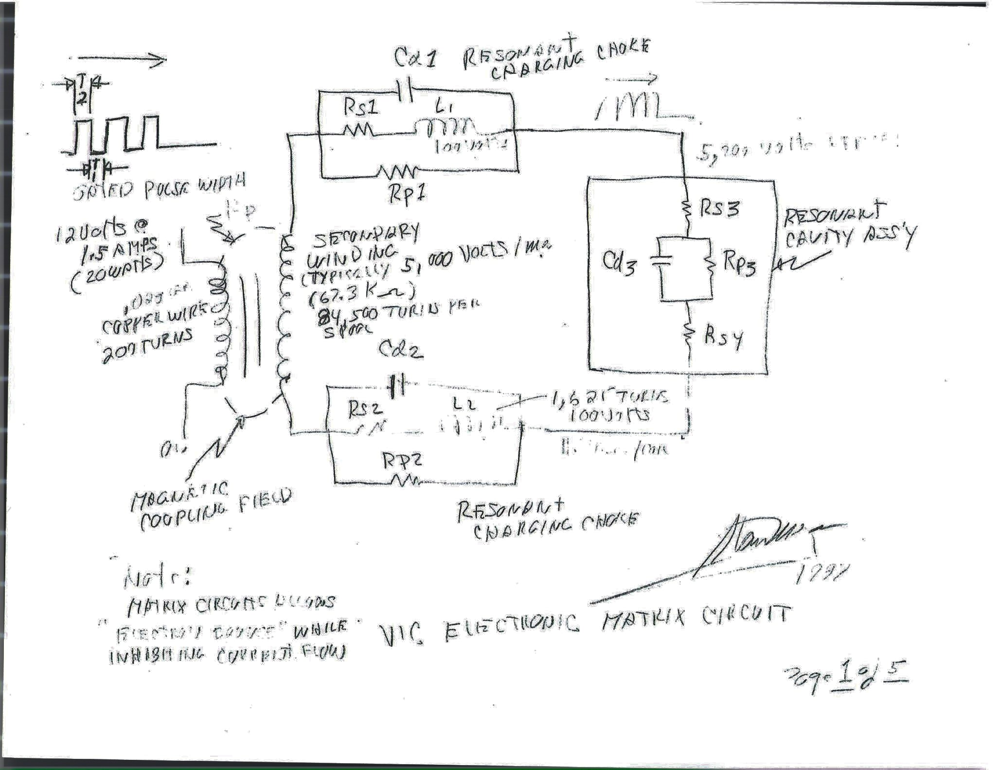
The drawing that became Figure 7-8 of memo WFC 426, with numbers on it that the memo does not carry. The note at the foot: Matrix circuit allows "electron bounce" while inhibiting current flow.
Page 2 of 5: Secondary winding bobbin
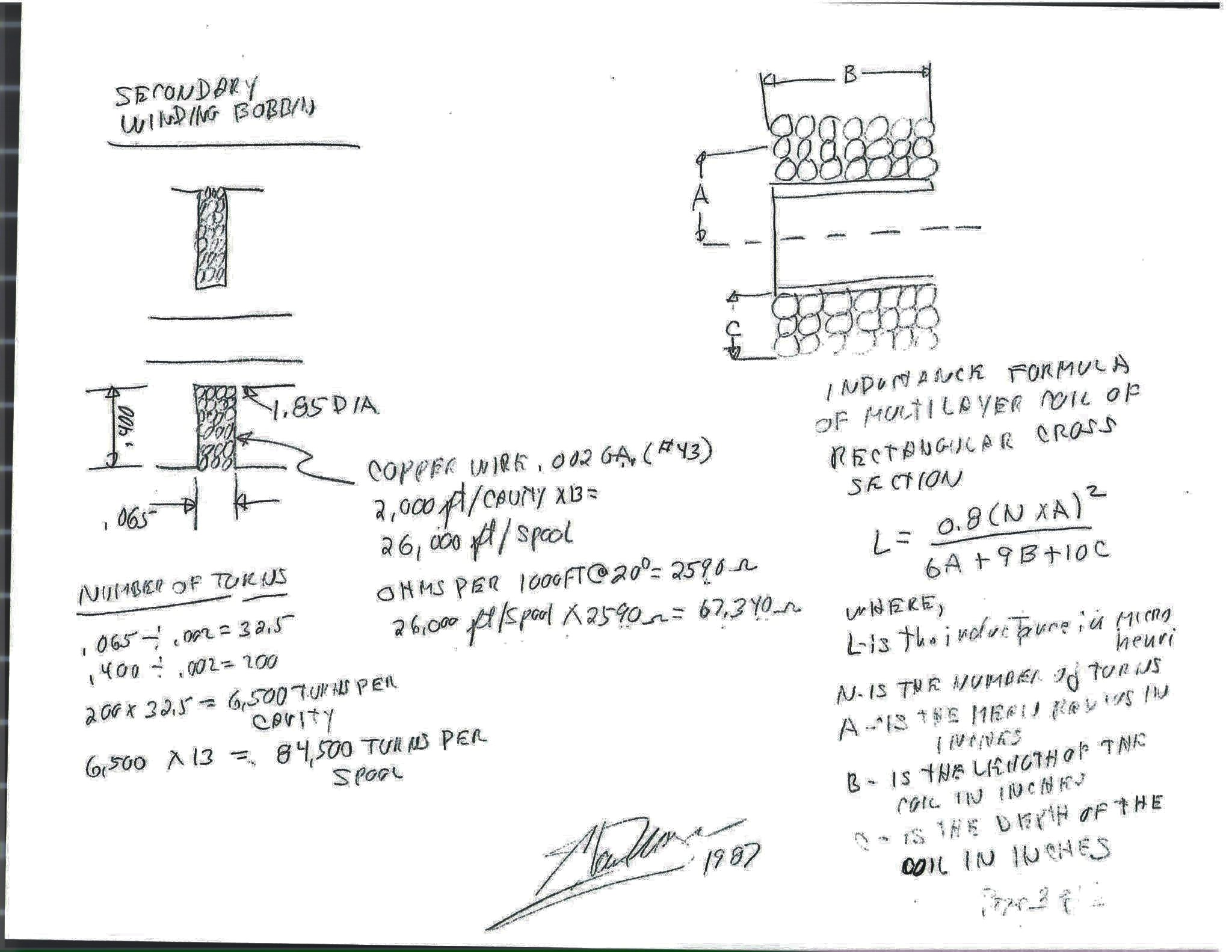
The formula is Wheeler's 1928 approximation, copied with its units. The 2,590 ohms per thousand feet is exact for .002 in copper (the archive's check gives 2,587). 26,000 ft at that figure is 67,340 ohms; page 1's "62.3 kΩ" is the same wire at 24,000 ft, twelve cavities rather than thirteen.
Page 3 of 5: Primary coil cavity; resonant cavity, bifilar wound
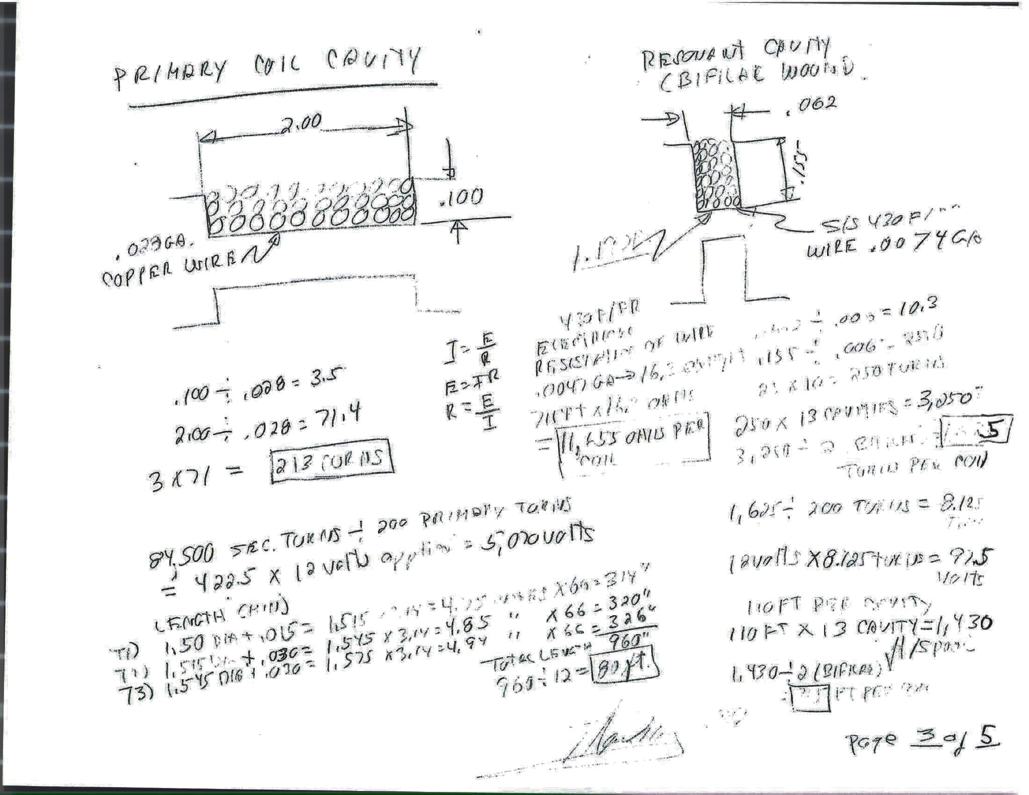
The turns ratio gives the secondary's 5,070 volts, and the same ratio applied to each choke, which is a winding on the same core, gives 97.5 volts. 5,070 + 97.5 + 97.5 is 5,265, which is the "5,200 volts applied" of page 1 within the rounding of the turn counts.
Page 4 of 5: 430 F/R stainless wire, the resistance of a foot
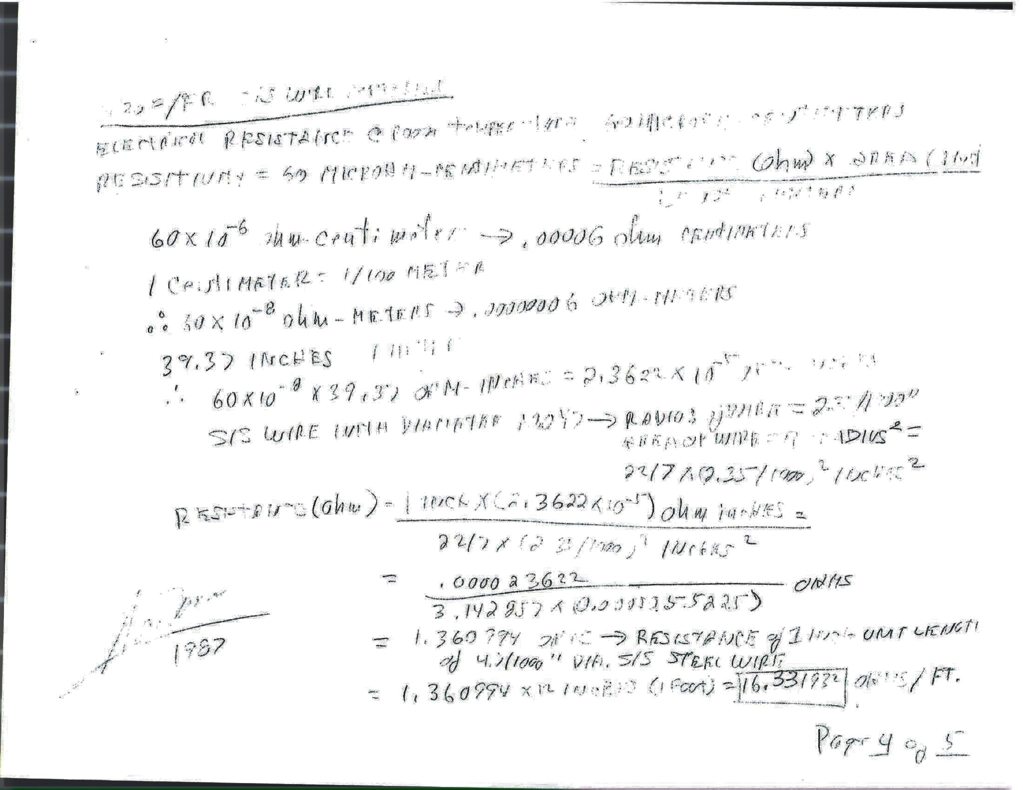
The working is correct to every figure. Sixty micro-ohm-centimetres is the published resistivity of 430 stainless, and the archive's own check of a foot of .0047 in wire gives 16.34 ohms. The memo on circuit resistance carries the result ("typically 11.6 KΩ") and the memo on capacitance carries the resistivity; this page is where the one became the other.
Page 5 of 5: Resonant cavity, tapered pin configuration
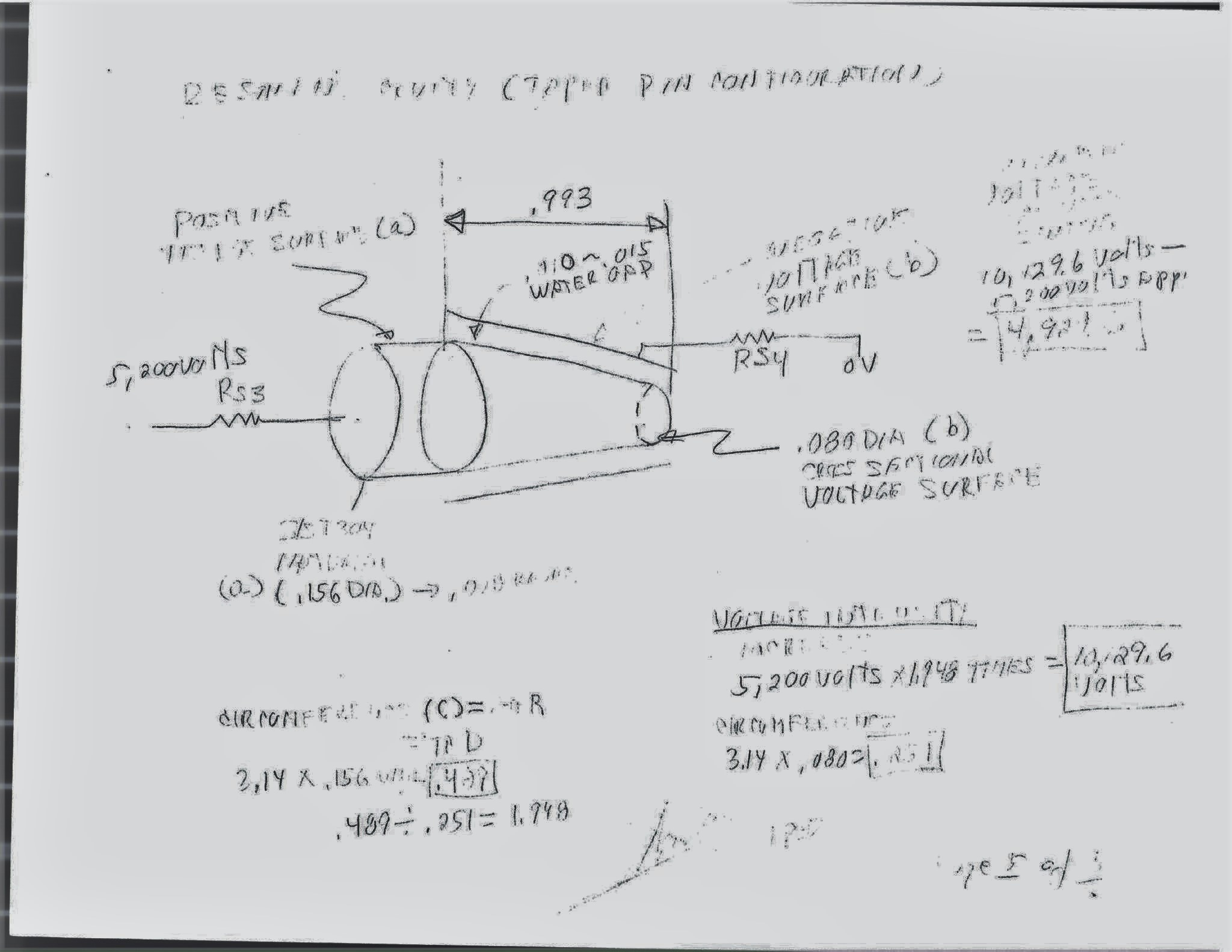
The ratio 1.948 is the ratio of the two circumferences, which is the ratio of the two radii. For a pin inside a bore whose gap shrinks in proportion to the pin, the field at the pin surface does rise by that ratio toward the narrow end; for a gap held at .010 all the way, the field is nearly flat along the taper; for a gap closing from .015 to .010, it rises by about one and a half. What rises is the field, not the voltage: the voltage at the pin is the voltage the chokes deliver. The memo on the water fuel injector describes the same taper as a "voltage wave-guide" in which "voltage amplitude intensity increases uniformly" toward the port.
Beside the memos
| The number | This page | The memo |
|---|---|---|
| Primary wire | .028 in copper, 200 turns | "22 AWG (.028) copper wire, 5.1933 ohms per pound", memo on capacitance |
| Secondary wire | .002 in (#43) copper, 84,500 turns | "35 AWG (.007) copper wire", the same memo |
| Choke wire | .0047 in 430 F/R stainless, 1,625 turns each | "430F/FR 36 AWG (.006) stainless", the same memo |
| Choke resistance | 11,655 ohms per coil | "typically 11.6 KΩ", memo on circuit resistance |
| Resistivity | 60 microhm-centimetres | "60 micro ohms per centimeter" |
| Secondary volts | 5,070 by turns ratio | "typically 5,000 volts" |
The estate transformer Don Gabel measured in 2009 is a different winding altogether, 29 gauge copper throughout: his readings are here.
Provenance
- Shelf
- Stan Meyer Publications
- Book
- Working papers
- File
- database/content/pages/vic-pencil-pages-1987.json
- Rights
- Photographs of five pages signed 'Meyer 1987', circulated on Facebook in July 2022 and posted to the archive's Discord by a member on 18 August 2024. Reproduced for research; the pages are Stan's, the transcription and the checks are the archive's.