

patent · WO1982001395A1
Power plant and process utilizing gravitational force
29 April 1982
Text Report a misread
Page 1bibliographic recordscan →
PCT
WORLD INTELLECTUAL PROPERTY ORGANIZATION
International Bureau
INTERNATIONAL APPLICATION PUBLISHED UNDER THE PATENT COOPERATION TREATY (PCT)
(51) International Patent Classification 3 : (11) International Publication Number: WO 82/ 01395
eB a0 F03G 7/02 . (43) International Publication Date: 29 April 1982 (29.04.82)
(21) International Application Number: = PCT/US81 /01382
(22) International Filing Date: 13 October 198! (13.10.81)
(31) Priority Application Number: 197,314
(33) Priority Country: US
(71X72) Applicant and Inventor: BUCKNAM, Donald, C.
(74) Agents: NEWMAN, E. Robert et al.; Henderson & Sturm, 990 Woodmen Tower, Omaha, NB 68102 (US).
(81) Designated States: AT (European patent), AU, BR, CF (OAPI patent), CG (OAPI patent), CH (European patent), CM (OAPI patent), DE (European patent), DK, FI, FR (European patent), GA (OAPI patent), GB
(European patent), JP, LU (European patent), NL (European patent), NO, SE (European patent), SN (OAPI patent), SU, TD (OAPI patent), TG (OAPI patent).
Published
With international search report.
With amended claims and statement.
(54) Title: POWER PLANT AND PROCESS UTILIZING GRAVITATIONAL FORCE
(57) Abstract
Power plant and processes for converting gas expanding energy sources into useful forms. A piston (13, 13a, 13c, 13d and 13e) containing a magnet (38) and able to free fall within an enclosed cylinder (12, 12a, 12c, 12d and 12e), having a center portion (15) surrounded by an induction coil (19) is repeatedly impelled upwards, thereby inducing an alternating electric current in the coil (19). In a preferred mode, a mixture of fuel and air is ignited beneath the piston (13), and in response to the piston’s upward motion, compressed air is pumped into a reservoir (14). In a first alternative mode, fuel is ignited at both ends of the cylinder, in a second, the heat of concentrated solar energy is directed onto a liquid (47) in the bottom of the cylinder (12c), in a third, hydrogen is burned below the piston (13d) to create heat which vaporizes water, and in a fourth, hydrogen is burned at both ends of the cylinder (12e).
ca Oo . oe Lona ie
Page 2scan →
For the purposes of information only
Codes used to identify States party to the PCT on the front pages of pamphlets publishing international applications under the PCT. AT Austria
AU Australia
BR Brazil
CF Central African Republic CG Congo
CH Switzerland
CM Cameroon
DE Germany, Federal Republic of DK Denmark
FI Finland
FR France
GA Gabon
GB United Kingdom
HU Hungary
JP Japan
Democratic People’s Republic of Korea Liechtenstein
Luxembourg
Monaco
Madagascar
Malawi
Netherlands
Norway
Romania
Sweden
Senegal
Soviet Union
Chad
Togo .
United States of America
Page 3scan →
Power plant and process
Utilizing gravitational force
Technical Field
This invention relates generally to power plants and processes
5 for converting energy from fuel or other sources for expanding or contracting gases into useful forms of energy which incorporate enclosed expansion chambers, wherein gases expand or contract anterior to a piston slidably operable within a cylinder and more particularly to such processes and devices which do not require mechanical means of transferring the energy from the piston or a structure such as a flywheel to serve as a reservoir of potential and kinetic energy.
Background Art
Conventional internal (gas) or external (steam) combustion engines have long been employed to convert fuel energy into various forms of stored energy or to operate moving apparatus. Such devices have traditionally employed mechanical means of transferring the anergy such as connecting rods, cranks, and crankshafts. Also, they generally require a flywheel of greater or lesser affect depending upon various factors, such as the number of pistons, the massiveness of engine parts, and the requirements for smooth and constant flow of energy. In addition, other conventional parts are required, such as piston pin bearings, crosshead bearings, crank pin bearings, and journal end bearings, all need lubricating means. The momentum acquired by the piston must be cancelled by the crank at the end of every stroke.
If the device employs internal combustion, either a crankcase or turbine is -required. If it uses external combustion, a burner, boiler, turbine and smokestacks are needed. (ALL of the latter are dispensed with in the present invention.)
Page 4scan →
To meet ‘demands for strength and stress, such auxiliary parts require additional materials, all of which reduce the ratio of energy available to perform work to the fuel consumed. Correspondingly, downtime for maintenance and repairs is reduced. Furthermore, applications such as power plants, which are designed to produce great quantities of energy, have size limitations governed by the strength and stress-withstanding properties of available materials.
Disclosure of the Invention
A piston containing a magnet is repeatedly impelled upwards within an enclosed cylinder having a load-connected electrical conductor coil surrounding its center portion. Alternating electric current is induced in the conductor coil in response to the upwards
‘and downwards movements of the magnet. The preferred embodiment provides for the injection and ignition of fuel near the lower end of the cylinder and the storage of compressed air produced by the upward motion of the piston in a reservoir to be then used to assist in exhausting contaminated gases, to provide more complete combustion, and to provide an additional source of energy in the form of compressed air.
An alternate embodiment does not include a compressed air reservoir, but provides for the injection and ignition of fuel alternately at both ends of the cylinder. .
Another alternate embodiment includes a compressed air reservoir to provide an additional source of energy and utilizes concentrated solar energy as a source of heat energy by directing it through a transparent structure in the upper end of the cylinder and a transparent core in the piston onto a black colored liquid in its lower end so that the liquid will vaporize.
Yet other embodiments employ burning hydrogen to form water, first creating heat and pressure and then a vacuum beneath and then above the piston.
Thus, in addition to gravity acting alone and a _ second combustion chamber at the upper end, the other means for returning the piston to its starting position are air compressed above the piston and the condensation of vapor when concentrated solar energy is used to expand a liquid beneath the piston or hydrogen is burned in the presence of atomized water.
Page 5scan →
An object of the present invention is to provide a process for converting energy into useful forms without employing expensive, heavy and dangerous moving parts, such as connecting rods, cranks, crankshafts, and flywheels.
Another object of the invention is the economic conversion of fuel or solar energy into electrical energy regardless of the size of the device.
Still another object of the invention is to circumvent the limits imposed by mass, inertia, momentum, wear maintenance, and manufacturability of the parts.
A further object of the invention is to convert fuel or solar energy into compressed air for use as a supplemental source of stored energy.
Still further objects are to eliminate costly and massive parts, reduce the consumption of fuel, and reduce pollution.
Yet another object is to provide a simpler device, less expensive to build and thus requiring less fuel than would be otherwise required.
Yet a further object of the invention is to ‘utilize space occupied by the secondary parts of a conventional engine for the principle parts of the electrical energy generating parts of the present invention.
Other objects, advantages and novel features of the present invention will become apparent from the following detailed description of the invention when considered in conjunction with the accompanying drawings.
Brief Description of the Drawings
Fig. 1 is a diagrammatic fragmentec, cross-sectional side view of the preferred embodiment wherein a Grive assembly comprising an air reservoir is shown;
Fig. 2 is a diagrammatic fragmented, cross~sectional side view of an alternate embodiment wherein fuel injecting, igniting and exhaust structures are shown at both ends of the cylinder;
Fig. 3 is a diagrammatic fragmented, cross-sectional side view of an alternate embodiment wherein a structure for vaporizing and expanding a liquid by concentrated solar energy is shown;
Page 6scan →
Fig. 4 is a diagrammatic fragmented, cross-sectional side view of an alternate embodiment. wherein structure for burning hydrogen below the piston assembly. and a drain release valve for surplus water is shown; .
Fig. 4a shows the drain release valve of Fig. 4 in its release attitude;
Fig. 4b is a sectional view of the embodiment of Fig. 4 taken through line 4b-4b of Fig. 4;
Fig. 5 is a diagrammatic fragmented, cross-sectional side view of an alternate embodiment wherein structure for burning hydrogen below and above the piston assembly and two drain release valves are shown; and ;
Fig. 5a is a sectional view of the embodiment of Fig. 5 taken through lines 5a-5a of Fig. 5.
Modes for Carrying Out the Invention
Preferred Mode
Referring now to the drawings, wherein like reference numerals designate identical or corresponding parts throughout the five embodiments, and more particularly to Fig. 1, the preferred embodiment, the power plant is depicted generally as (11) includes a cylinder assembly (12), a piston assembly (13), and an air reservoir (14). The cylinder assembly (12) is comprised of a cylinder wall (16), a lower end wall (17) attached to the cylinder wall (16) at or near the ground, an upper end wall (18) attached to the upper end of the cylinder wall (16), and a load-connected electrical conductor coil (19) surrounding a center portion (15) of the cylinder. The center portion (15) of the cylinder (16) must be of a non-mag-— netically-responsive material of either metal or ceramic. By properly supporting the upper half of the cylinder, the walls of the central part of the cylinder (15) between the ends may be relatively thin, thus permitting the coil to be in close proximity to the magnetic piston. As compared to the center portion (15), most other parts of the cylinder assembly (12) especially the end walls, are subject to higher demands for structural strength, heat resistance, and pressure resistance. Materials with appropriate properties are well known and are required for the device to function properly.
Page 7scan →
‘The upper end wall (18) of the cylinder assembly (12) has an
, inlet port (21) with a spring-biased valve (22) mounted therein and an outlet port (23) witha spring-biased valve (24) mounted therein which is connected by a tube (26) to first end (20) of air reservoir 5 (14). Adjacent the lower end wall (17), located in cylinder wall (16) igs an exhaust outlet port (27) for exhausting contaminated gases with» a mechanically operated spring-biased exhaust valve (28) mounted in it. A’ second inlet port (29) located in protrusion (30) of cylinder wall (16) intermediate the ends of the cylinder assembly (12), having
10 valve (31) mounted in it, is connected by tube (32) to second end (25) of air reservoir (14).
Completing the cylinder assembly (12), compressed air supply (33) (which could be a compressed air reservoir or a conventional starter air pump), a conventional fuel injector (34), and a conven- 15 tional fuel ignition structure (36) are connected to cylinder assembly (12) through a protrusion in the cylinder wall (16) adjacent the end wall (17). In addition, electronic timing devices (not shown)
and hydraulic or solenoid switches (not shown) are provided for controlling spring-biased valves (22), (24), (28), and (31), -fuel
20 injector (34), and ignition structure (36), so as to synchronize their functioning in accordance with the process for converting energy as hereinafter described.
The piston assembly (13) is slidably operable within the cylinder assembly (12) and includes an intermediate bar magnet in the 25 form of a magnetic disc (38) which has a lower ceramic plate (39) and an upper ceramic plate (41) secured to its lower and upper ends, respectively, to serve as piston rings. The polar axis of the bar magnet (38) is oriented so that it coincides with the longitudinal , axis of the cylinder assembly (12). The upper and lower plates (39) 30 and (41), may be of other non-magnetically-responsive material such as copper or aluminum.
In the present invention, the momentum needed to achieve the exhaust, intake and compression cycles in a conventional fashion, resides entirely within the piston and that which was lost to turn a
35 crank is now available to compress the charge. Furthermore, there is practically no limit to the speed of the piston or distance of its d 8 travel. Increasing its velocity results in an increased compression ratio, a correspondingly smaller combustion chamber. The invention, having no crank, makes varying the compression ratio an easy matter, which also permits employment of various types of fuels. Also by increasing the fuel delivered to or decreasing the load placed upon the device, the speed of the piston may be increased without limit. It may be slowed down by increasing the pressure and quantity of air it is pumping or the amount of electricity it is producing. With a vertical cylinder and unconnected piston, losses due to. friction should be minimal.
Air reservoir (14) has a take-off tube (42) with check valve (43) mounted therein. AS will be noted hereinafter, air reservoir
-(14) may be utilized as a supplementary source of stored energy by tapping compressed air through tube (42). In addition, storing and releasing energy in this manner further provides for fluctuations in load.
The process of convert ing energy with the power plant (11) includes a starting phase and a repeating cycle phase. Prior to initiating the starting phase, the piston assembly (13) is held at rest at starting position (44) by a small column of compressed air maintained by compressed air supply (33). Compressed air supply (33) then lifts the piston assembly (13) to an apex position (46) near upper end wall (18). During this operation all ports except outlet port (23) are in closed position so as to permit the column of air above piston assembly (13) to pass through tube (26) into air reservoir (14), creating a supply of compressed air therein. When piston assembly (13) reaches apex position (46), compressed air supply (33) is turned off and valvé (28) in outlet port (27) is allowed to open so as not to impede the free fall of piston assembly (13). The free falling piston assembly (13) will pull open valve (22), permitting fresh air to enter through inlet port (21) and allow valve (24) to close, sealing off the supply of compressed air now in air reservoir (14). When piston assembly (13) has reached a point where, after exhaust valve (28) is closed the air being compressed beneath it will not stop it from reaching starting position (44), exhaust valve (28) is then closed. The mass of the piston and the
Page 9scan →
‘time of the closing of valve (28) will determine the compression ratio and therefore the size of the combustion chamber.
Prior to piston assembly (13) returning to starting position (44), fuel is injected by fuel injector (34), and, as piston assembly (13) reaches starting position (44), the fuel is ignited, forcing piston assembly (13) again to apex position (46). During this ascent of piston assembly (13) the spring-biased valves (22) and (24) will direct the column of air above piston assembly (13) to enter through tube (26) into air reservoir (14), further compressing the air therein so long as valve 31 continues to be held in a closed position. However, as piston assembly (13) ascends past inlet port (29), spring-biased valve (31) is allowed to open-and admit a charge of compressed air below the piston which assists in pushing the piston upward and expelling the contaminated gases beneath piston assembly (13) downward through exhaust port (27) and supplies a fresh charge of compressed air beneath the piston assembly (13). After a sufficient charge of compressed air is passed through inlet port (29), spring-biased valve (31) is again held closed, causing the column of air remaining above piston assembly (13) to be forced into air reservoir (14) as the momentum of the piston assembly (13) continues to carry it up to the apex position (46). The first cycle of the repeating cycle has now been completed and the second cycle is initiated as was the first by piston assembly (13) beginning its second free fall towards cylinder assembly end wall (17).
The timing of each step of the process is controlled by electronic timing devices through conventional switches operated by solenoids or, by hydraulic or mechanical controls where necessary. Electronic timing devices which have provisions for adjustments to allow for variations in fuel, atmospheric pressure, temperatures, etc., are well known; and, under a given set of parameters, gravity being constant, once an appropriate timing sequence is determined, the energy converting device (11) will continue the repeating cycle. By employing a plurality of valves, directional intake and outlet ports, as well as baffles (not shown); adequate breathing and forcing of contaminated gases downwards without mixing with intake air, may be insured.
Energy will be converted into electrical energy as the magnetic
Buseag
Ly. WIEO 10 forces of the magnetic disc (38) pass by the electrical conductor coil (19), thereby inducing an electric current. Means for converting the alternating current thus produced into suitable frequencies and voltages for transmission over long distances are well known and now shown herein. Also, stored energy is available in the form of compressed air by opening valve (43) mounted in take-off tube (42).
First Alternative Mode
Referring now to Fig. 2, an alternate embodiment of the power plant is depicted generally as (11a) and includes a cylinder assembly (12a) and a piston assembly (13a). This embodiment differs from the preferred embodiment in that it does not include an air reservoir with its attendant parts nor inlet and outlet ports with valves for pumping fresh air in its upper end wall, but has instead, adjacent its upper end wall (17b), connected to cylinder assembly (12a) through cylinder wall (16a), the same elements power plant (11) has adjacent its lower end, with the exception of a compressed air supply structure (33). These elements include exhaust outlet port (27b) with Spring-biased exhaust valve (28b) mounted in it, fuel injector (34b) and fuel ignition structure (36b), all located in cylinder wall (16a) adjacent to upper end wall (17b). Intermediate the ends of cylinder assembly (12a) are one or more inlet ports (29a) located in protrusions (30a) in cylinder wall (i6a) and having valves (31a) mounted in them. In all other respects the power plant (lia) has parts parallel to those of power plant (11) and said parts are designated by corresponding numerals with the letter "a" appended thereto.
The process of converting energy with the power plant (11a) includes a starting phase identical to that of the starting phase of power plant (11), piston assembly (13a) being lifted by compressed air from (33a) to apex position (46a) near upper end wall (17b) and exhaust valve (28b) being allowed to open so as to permit the column of air above piston assembly (134).to pass through exhaust outlet port (27b). As in the preferred embodiment, after piston assembly (13a) reaches apex position (46a), compressed air supply (33a) is turned off and exhaust valve (28a) is allowed to open and valves (28b) and (31a) are also held open so as to permit the free fail of 11 piston assembly (13a).
‘ As the piston assembly (13a) descends past inlet port (29a), inlet valve (31a) is open, and outlet valves (28a) and (28b) close, causing the descending piston assembly (13a) to compress the air 5 remaining beneath it while drawing air in above it through intake port (29a). Then duplicating the process of power plant (11), fuel is injected prior to piston assembly (13a) reaching starting postion (44a) and ignited as it reaches starting position (44a). Valve (31a) then closes and exhaust valve (28b) opens permitting the exhaust to 10 escape. As piston assembly (13a) ascends past inlet port (29a) valve (31a) opens and valve (28b) closes, drawing in clean air beneath the piston assembly (13a) and compressing air above it as ‘the momentum of ~ the piston carries it to its apex position.
Prior to piston assembly (13a) reaching apex position (46a), 15 fuel is admitted by fuel injector (34b). As piston assembly (13a) reaches apex position (46a), ‘the highly compressed air and fuel mixture above it is ignited by ignition structure (36b). Intake valve (31a) is then closed and exhaust valve (28a) is opened. At this instance the repeating cycle of power plant (11a) is initiated and 20 all of the valves, fuel injectors, and ignition structures, being controlled by electronic timing devices (not shown) operate in the same sequence as described above following the first descent of piston assembly (13a) from apex position (46a). In the case of energy converting device (11a), the material requirements with respect to 25 cylinder assembly (12a) and piston assembly (13a) are identical to those of energy converting device (11) and electronic timing devices will maintain sequential control, after necessary adjustments, of the various elements including conventional valve-switching gear. Fuel energy will be converted into electrical current by induction in like
30 manner.
As in conventional internal combustion engines, fresh air is ° admitted through inlet port (29a) whenever atmospheric pressure (plus or minus 1033.2 g/cm”) exceeds the pressure behind the piston as it moves up or down; however, superchargers may be utilized if desired.
35 Second Alternative Mode
Referring now to Fig. 3, a second alternate embodiment of the D))
Burleag
} ompfi
VY, WrO yy 12 power plant is depicted generally as (lic) and also includes a cylinder assembly (12c) and a piston assembly (13c), as well as an air reservoir (14c). In‘this embodiment, at least two complexes of cylinder assembly (12c), piston assembly (13c), and air reservoir (14c) are synchronized so as to produce a more constant supply of converted energy and to maximize the use of sunlight. Although an air reservoir (14c) is shown for each power plant complex, a single air reservoir could serve several such complexes. This embodiment differs from the preferred embodiment in that air reservoir (14c) is not connected to an inlet port in cylinder wall (16c) intermediate the ends of the cylinder assembly (12c) and in that cylinder assembly (12c) has (in place of a valved outlet port, a compressed air supply means, a fuel injector, and a fuel ignition structure) a black colored liquid (47) contained beneath starting position (44c) and adjacent its lower end wall (17c) a volume of inert gas (not shown) above liquid (47), and a concentrated solar energy assembly (48).
Concentrated solar energy assembly (48) for vaporizing the black colored liquid (47) includes conventional heliostat reflectors (49), , parabolic concentrator-reflector (51), concave lens (52), movable reflector (53), stationary reflector (54), solid transparent portion (56) of upper end wall (18c), and solid transparent core portion (57) of the piston assembly (13c). In all other respects power plant (11c) has parts parallel to those of power plant (11) and said parts are designated by corresponding numerals with the letter "c'" appended thereto.
As in the Preferred Mode, the process of converting energy with power plant (1ic) includes a starting phase and a repeating cycle phase. Prior to initiating the starting phase, the piston assembly (13c) is held at rest at starting position (44c) by resting upon the volume of inert gas above the black colored liquid (47). The inert gas serves to produce the effect of a bounce chamber for piston assembly (13c). In this embodiment, the starting phase is initiated by the vaporization of Liquid (47) when concentrated solar energy is directed upon it. The black colored liquid (47) is thereby vaporized forming an expanding gas which lifts the piston assembly (13c) to apex position (46c) near upper end wall (18c). During this operation, 13 the column of air above piston assembly (13c) passes. through outlet port (23c) and tube (26c) into air reservoir (14c) creating a supply of compressed air therein. When the vapor expanding beneath piston assembly (13c) is sufficient to lift it to apex position (46e), 5 movable reflector (53) of solar energy means (48) directs concentrated solar energy to another stationary reflector (54) of another complex, allowing piston assembly (13c) to free fall as black colored liquid (47) cools and condenses. The free falling piston assembly (13c) will pull open valve (22c) permitting fresh air to enter
10 through inlet port (21c) and allow valve (24c) to close, sealing off the supply of compressed air now in air reservoir (14c). Prior to piston assembly (13c) returning to starting position (44c), and as
“ the vaporized black colored liquid (47) has begun to condense and accumulate adjacent to lower end wall (1i7c), concentrated solar
15 energy means (48) is again directed to the original stationary reflector (54) in order that the black colored liquid reaccumulating in the bottom of cylinder assembly (12c) is maintained at whatever temperature above its boiling point which is desired with respect to operational requirements.
20 When piston assembly (13c) has reached its starting position (44c), the first repeating phase is initiated by the revaporization of the black colored liquid (47). In this embodiment of ‘the energy converting device the only difference between the starting phase andthe repeating phases is that the temperature of the black colored
25 liquid (47) is ambient only in the starting phase and is higher during any repeating phase. Thus, the velocity of the ascending piston may be varied by controlling the operating temperature of the condensed black colored liquid (47). There must be enough inert gas above the water in the cylinder to provide a bounce chamber at the
30 bottom of the cylinder which will deter the falling piston from ever physically striking the liquid. Were the piston to suddenly free fall against the liquid upon the setting of the sun or sudden moving in of cloud cover, the shock would undoubtedly do great damage to the cylinder unless other cushioning steps were taken.
35 It is believed that the method for producing and directing a beam of concentrated solar energy may not be generally known by those
4y>_ WRO ow : NVE pnatioNy 14 skilled in the pertinenet art and, therefore, the following explanation is included herein. Sunlight is reflected by heliostat (49), which is comprised of a large array of steered mirrors. As the * sun moves across the sky, the heliostat (49) directs the beams to a
5 parabolic concentrator-reflector (51) which is fixedly mounted and which directs the collection of beams through a concave lens (52). The lens (52) causes the collection of beams to become a concentrated parallel beam and is lecated so as to direct this beam onto a movable mirror (53). Mirror (53) is controlled by solenoid of hydraulic means
10 to alternately direct the concentrated solar energy to the several stationary mirrors (54) where the beam is alternately reflected through transparent portion (56) of upper end wall (18c) and transparent core portion (57) of piston assembly (13c) onto the black colored liquid (47) in each cylinder assembly (12c).
15 As in the case of power plant (11) and (lia), the material requirements with respect to cylinder assembly (12c) and piston assembly (13c) are identical except for the transparent portion (56) in upper end wall (18c) and the’ transparent core (57) in piston assembly (13c). A suitable agent for coloring the Liquid (47) black
20 is graphite containing some oil lubricant. Electronic timing devices will maintain sequential control of the movable mirror (53). After necessary adjustments of the various elements including conventional valve switching gear, concentrated solar energy will be converted into electrical current by induction in like manner. Compressed air
25. stored in air reservoir (i4c) provides an additional source of converted energy.
The inventor believes that a more efficient way to utilize solar energy is to convert it first to chemical energy so as to dissociate the elements of a liquid into its elements hydrogen and oxygen with :
30 the aid of a cataylist, such as a rhodium compound, and later liberate this stored solar energy by recombining and releasing their heat inside an engine. For an explanation of this method of producing hydrogen and oxygen see Popular Science, Science Newsfront, p. 61
(May 1980). The stored chemical energy far exceeds the latent heat - 35 required to achieve the phase change which converts water into vapor.
There might be enough heat given off in the process of forming water
4, wipo
Sernatio
Page 15scan →
that the pressure of the vapor immediately after its formation may be the same as that of the hydrogen and oxygen gas immediately before its burning.
Third Alternative Mode
Referring now to Figs. 4 and 4a, an additional alternate embodiment of the power plant is depicted generally as (11d) and also includes a cylinder assembly (12c) and a piston assembly (13d), as well as an aizx reservoir (14d). This embodiment is similar to the embodiment employing concentrated solar energy in that air reservoir (14d) is not connected to an inlet port in cylinder wall (16d), is different than the concentrated solar energy embodiment in that it does not employ concentrated solar energy nor any of the complementary elements and structures, and is similar to the preferred embodiment in that it employs fuel injector (34d) and ignition structure (36d) for the introduction and ignition of a fuel; in this embodiment that fuel is hydrogen gas.
This hydrogen burning embodiment also includes oxygen injector (58), water injecting atomizer (59), second hydrogen injector (61), second oxygen injector (62), water vapor condensing assembly (63), and automatic drain relief valve assembly (64).
The water vapor condensing assembly (63) includes vapor outlet port (66) with a spring-biased. valve (67) mounted therein connecting tube (68) to a separate condenser (69) which contains a near perfect vacuum and is enveloped by chilled water (71).
Drain release valve assembly (64) includes cylinder (72) which revolves within a recess ‘within thickened lower end wail (17d). Said cylinder (72) has a pocket (73) to receive condenseé water vapor collected by concave depression (74) of end wall (17¢) and throat (76) of end wall (17d) and eject said condensed water vapor through outlet tube (77). Outlet tube (77) may be connectec to separate condenser (69) either directly or through connecting tude (68). Tube (77), being connected to condenser (69) which contains @ vacuum, will also contain a vacuum; said vacuum will assist gravity in removing water from pocket (73). Drain release valve assembiy (64) also includes pressure control structure (78) which has activating piston (79), compression spring (81), shaft (82), and connecting rod (83).
Page 16scan →
In operation, compression spring (81) holds activating piston (79) in taised position, as best can be seen in Fig. 4, until the pressure within cylinder assembly (12d) and beneath piston assembly (13d) rises to a pre-set level sufficient to force shaft (82) downwards to the position which can best be seen in Fig. 4a. Connecting rod (83) being pivoted between a fixed position on cylinder (72) and the lower end of shaft (82) will then cause cylinder (72) to rotate from its collecting position as can be seen in Fig. 4, to its dispensing position as can be seen in Fig. 4a.
In all other respects, power plant (11d) has parts parallel to those of power plant (11) and said parts are designated by corresponding numerals with the letter 'd'' appended thereto.
The process of converting energy with power plant (ild) is most analogous to that of the concentrated solar energy embodiment herein mext above described. Its starting phase is initiated by the injection of two parts hydrogen and one part oxygen beneath the piston assembly to lift it to a starting position (44d). Water is then injected through the atomizer or nozzle structure (59) simultaneously with the ignition of the gases beneath the ‘piston assembly. In this embodiment a laser or other type of igniter must be used because a spark plug will not function in the moist environment. This results in super-heated steam adequate to force piston assembly (13d) to apex position (46d) forcing the column of air above piston assembly (13d) through outlet port .(23d) and tube (26d) into air reservoir (14d). As the steam beneath piston assembly (13d) begins to condense, a vacuum is created which assists the return of piston assembly (13d) to starting position (44d).
After piston (13d) reaches apex position (46d), valve (67) opens port (66) to permit remaining water or water vapor to escape from the bottom of the cylinder to the cooled separate condenser (69), which always contains a near perfect vacuuz. Thus, a vacuum beneath the piston is provided for a longer period of time, thereby assisting gravity in returning the piston to starting position (44d). When piston (13d) has reached a position about half way down the cylinder, valve (67) is closed and hydrogen and oxygen injectors (34d) and (58)
in the lower end of the cylinder again admit a fresh charge of two 17 parts hydrogen and one part oxygen, respectively. When the new charge is released from pressurized containers into the partial vacuum, it expands, cools, and further increases the pressure, thus causing any remaining water vapor residing in the cylinder to condense on the cylinder walls. This precipitation provides an even greater vacuum, thereby allowing for the addition of more of the gaseous components of water.
As piston (13d), on its way down, starts to compress the new charge, its velocity is reduced by the increasing gas pressure beneath it. The water droplets continue to fall at the same, or increased, rate of speed and collect in concave depression (74) of endwall (17d), leaving a relatively pure mixture of hydrogen and oxygen gas immediately above the water and below the piston. The downward motion of the piston is eventually stopped by the increasing gas pressure, resulting is a bounce chamber effect at the bottom of the cylinder. When piston (13d) reaches starting position (44d), if the hydrogen beneath it does not pre-ignite, ignition structure (36d) ignites the mixture, turning the bounce chamber into a combustion chamber and initiating the first repeating phase. The heat of combustion of hydrogen and oxygen then vaporizes the water droplets still falling and collecting on the cylinder walls and in concave depression (74). The resulting tremendous quantity of heat vaporizes additional water to create more steam which again drives the piston to apex position (46d). Water injecting atomizer (59) provides this additional‘ water immediately before combustion occurs. Cooling within the cylinder, between combustions, reduces the need for removing excess heat which can now be tapped az the condenser.
If a long stem cylinder is usec, separate condenser assembly 63 may not be required. A fresh, cold, high pressure charge of hydrogen and oxygen could be admitted at various locations below the pistons, as by injectors (61) and (62), when che piston is still at apex position (46d) rather than after it has returned dewnward to a position midway between the upper anc lower ends of the cylinder. If the charge were admitted immediately below the pisten while the piston is at apex position (46d), the incoming mixture would cool and condense the water vapor residing there and draw the remaining water
Bukear
Ompi
4 wieo
Vie py, amy an® 18 vapor from below upwards. The resulting condensed water droplets falling down the cylinder walls or precipitating as rain would further condense the remaining water vapor below the piston.
‘Increased pressure, caused by the incoming mixture would also tend to condense the vapor.
Controls of conventional nature well known in the art are employed to balance the removal of water vapor through port (66) into separate condenser (69) and the removal of condensed water by drain relief valve assembly (64) with the quantity of water entering the cylinder assembly (13d) through water atomizer (59) and by reason of thé combustion of the injected hydrogen and oxygen. It should be appreciated also that either the water vapor port (66) or the drain relief valve assembly (64) alone could provide the function of removing surplus water.
Fourth Alternative Mode
Yet another embodiment of the power plant is depicted in Figs. 5 and 5a, which like the next preceding embodiment relies upon the ignition of a mixture of hydrogen and oxygen in the presence of atomized water. This embodiment which is indicated generally as (ile) differs from the previous embodiment in that it does not include an air reservoir with its attendant parts, nor an inlet port with valve for pumping fresh air through its upper end wall, but has, instead, adjacent its upper end wall (17f£), connected to cylinder assembly (12e) through cylinder wall (i6e), the same elements, power plant (11d) has adjacent its lower end. These elements include hydrogen injector (34£), fuel ignition structure (36f£), oxygen injector (58f), water vapor atomizer (59f), water vapor port (66f), spring-—biased valve (67£), and connecting tube (68f) for the transmission of water vapor to separate condenser (69). Power plant (ile) also has a drain relief valve assembly (64e) which has the same elements as valve assembly (64), said elements depicted by appending the letter "'e"™ to the corresponding numerals. i,
The piston assembly (13e) has within a magnetic disc (38e), a drain relief valve assembly (64f) which includes all of the elements of the drain release valve assembly (642), which in turn is identical to drain relief valve assembly (64) of power plant (11d), located in the thickened lower end (i7e) of cylinder assembly (12e), with th
Outfi
> tern ation
Page 19scan →
exception of drain pathway (77e). In lieu of pathway (77e) drain release assembly (64f) has a pathway (84) which serves to permit water to flow from drain release valve assembly (64f) into cylinder assembly (12e) beneath piston assembly (13e). In all respects, drain
5 release valve assembly (64e) and (64£) operate in the same manner as drain release valve assembly (64), except that pathway (84) directs the exiting water into the cylinder beneath piston (13e).
In all other respects, power plant (ile) has parts parallel to those of power plant (11d) and said parts are designated by
10 corresponding numerals with the letter "e" appended thereto.
The process of converting energy with the power plant (lle) includes a starting phase identical to that of the starting phase of power plant (11d), with the exception that all of the air above piston assembly (13e) has been replaced by steam which, upon condens-
15 ing, draws the piston assembly upward. The piston assembly (13e) is also lifted by super-heated steam from below, to apex position (46£) near upper end wall (17f).
Prior to piston assembly (13e) reaching apex position (46f), hydrogen injector (34f) and oxygen injector (58£) admit hydrogen and
20 oxygen in the ratio of two parts to one part, respectively, into cylinder assembly (12e) above apex position (46£), and as cylinder assembly (13e) reaches apex position (46f), additional water is admitted above apex position (46£) by water atomizer (59£) and simultaneously the ignition structure (36f) ignites the hydrogen. At
25 this instance the repeating cycle of power plant (lle) is initiated and all of the valves, injectors, and ignition structures, being controlled by electronic timing devices (not shown), also operate in the same sequence and in similar manner as described above the for starting phase of power plant (11¢).
30 Industrial Applicability
The industrial applicability of the power plant and process of utilizing gravitational force is believed to be manifest from the foregoing descriptions. Energy will be converted inzo electrical energy as the magnetic forces of the magnetic disc pass by the 35 conductor coil. Also, stored energy is available in the form of compressed air in the best mode, the second alternative mode, the
Dara mt At 20 third alternative mode and the fourth alternative mode.
Obviously, numerous modifications and variations of the present invention are possible in light of the above teachings. It is therefore to be understood that within the scope of the appended claims,
5 the invention may be practiced otherwise than as specifically de~ scribed therein.
“yp, WO WwW
NER Na TONY
Page 21scan →
I claim
1. A process for converting gas expanding energy sources into useful other forms of energy, such as inducing an alternating current in a coil, comprising the steps of:
5 holding a piston means forming a magnetic field at a starting position near a lower end of a cylinder means, also having an upper end, with a load-connected electrical conductor coil means surrounding it intermediate said ends thereof;
lifting said piston means to an apex position near an 10 upper end of said cylinder means thereby opening a spring-biased valve mounted in a first outlet port in said upper end in order to transfer the column of air above the piston means through a tube into a reservoir means;
permitting said piston means to initiate a repeating 15 cycle by free falling within said cylinder means thereby allowing said spring-biased valve in the first outlet port to close, opening a spring—biased valve mounted in a first inlet port in said upper end in order to admit a charge of fresh air and opening a spring-biased mechanically operated exhaust valve zounted in a second outlet port 20 in said lower end;
closing the valve in said second outlet port at the bottom of the cylinder when the piston means has fallen far enough to
‘enable it to compress as much fresh air beneath it to allow it to reach said starting point;
25 injecting fuel into the air in the cylinder means beneath said piston means starting position prior to its reaching said starting position;
igniting the fuel and air mixture at approximately the instant when said piston means has reachec said starting position 30 thereby forcing said piston means towards the upper end, again opening said first outlet port for transferring the column of air above and ahead of said piston means inte said reservoir; opening a valve mounted in a second inlet port, intermediate the lower and upper ends of said cylinder means, and 35 connected by pipe to a lower end of said reservoir means, as the
Suread
Wipo
ERNaTiowy
Mpg MEO 22 piston means passes upwardly by, in order that compressed air in the reservoir will enter the cylinder means behind the piston between the piston means and the lower end of said cylinder means and expel the contaminated gases through the second outlet port; and closing said second inlet port when the piston means has again reached a point near the upper end of the cylinder means and is in position to again free-fall for the next repetition of the cycle.
2. The process as defined in Claim 1 wherein said steps of holding the piston means at a starting position and lifting it to an apex position are carried out by admitting compressed air. ; 3. A device for converting fuel energy into useful other forms of energy, such as inducing an alternating current in a coil, comprising:
means for holding a piston means forming a magnetic field at a starting position near a lower end of a cylinder means also
’ havng an upper end, with a load-connected electrical conductor coil means surrounding it intermediate the ends thereof;
means for lifting said piston means to an apex position near the upper end of said cylinder means;
means for permitting said piston means to initiate a repeating cycle by free falling within said cylinder means to said starting position; ;
, means for injecting fuel into the air in said cylinder means beneath said piston means starting position and prior to said piston means reaching said starting position;
means for igniting the fuel and air mixture at approximately the instant when said piston means has reached said starting position thereby forcing the piston towards the upper cylinder end from where the cycle may again be repeated; and means for sequentially timing the injecting and igniting of the fuel, the admitting air and fuel, and the exhausting of air and contaminated gases including:
a first outlet port in the upper end of the cylinder having a spring-biased valve mounted therein for transferring the column of air above the piston, as’ it ascends, through a tube con nected to an upper end of a reservoir means;
Davaont it
Wr. WirO RY, 23 a first inlet port in the upper end of the cylinder having a spring-biased valve mounted therein for admitting fresh air above the piston, as it falls;
a second outlet port, in the lower end of the cylinder having a spring-biased mechanically operated valve mounted therein for permitting the piston to fall initially and expel contaminated gases without compressing air beneath it so that it may be closed at a predetermined time so as to permit the piston to reach its starting position and to begin to compress air beneath it;
a second valved inlet port, intermediate the lower and upper cylinder ends and connected by a tube to a lower end of the reservoir means for admitting compressed air from the reservoir means into the cylinder to expel contaminated gases through the second outlet port and provide a fresh charge of air after the piston passes upwardly by said second inlet port; and electronic timing means for synchronizing the holding, lifting, and free fall permitting of the piston means; the injecting and igniting of the fuel; and the opening and closing of the valves. ;
4, The device as defined in Claim 3 wherein the means for holding the piston means at a starting position, lifting it to an apex position, and permitting it to free fall is a controlled source of compressed air which may be same as reservoir (14).
5. The device as defined in Claim 3 or 4 wherein the reservoir means (14) has a third outlet port intermediate the ends thereof with a valve mounted therein for tapping the surplus compressed air therein as an additional source of useful energy.
6. A process for converting fuel energy into useful other forms of energy, such as inducing an alternating current in a coil, comprising the steps of:
holding a piston means forming a magnetic field at a starting position near a lower end of a cylinder means having a load-connected electrical conductor coil means surrounding said cylinder means intermediate said ends thereof;
lifting said piston means to an apex position near an 24 upper end of said cylinder means thereby opening a spring~biased valve mounted in a first outlet port near said upper end for exhaust~ ing the column of air above the piston means;
permitting said piston means to initiate a repeating cycle by free falling within said cylinder means while holding the valve near said first outlet port open and while holding a spring-biased mechanically operated valve mounted in an exhaust outlet port near said lower end open until the piston passes downwardly past an inlet port intermediate said cylinder ends so that the air remaining below the piston will then be compressed, said inlet port having a spring-biased valve mounted therein, thus permitting air to enter therethrough above the piston whenever the pressure is less than plus or minus 1033.2 g/om-s injecting fuel inte the air in the cylinder means beneath said piston means starting position prior to its reaching said starting position;
igniting the fuel and air mixture at approximately the instant when said piston means has reached said starting position, thereby forcing the piston towards said upper end and thereby closing the inlet port and opening the first outlet port so that contaminated gases will be expelled therethrough;
holding the first outlet port closed, after the piston passes upwardly by the inlet port, thus compressing eir ahead and above the piston and permitting air to enter through the inlet port behind and below the piston;
injecting fuel into the air in the cylinder means above said apex position prior to ‘he piston means reaching said apex position; and igniting the fuel and air mixture at approximately the instant when said piston means has reached said apex position, thereby forcing the piston towards said lower end and initiating the next repetition of the cycle.
7. The process as defined in Claim 6 wherein said steps of holding the piston means at a starting position, lifcing it to an apex position, and permitting it to free fall are carried out first by admitting compressed air, and then allowing it to escape.
Bureag
Wipo
Pears
Page 25scan →
8. A device for converting fuel energy into useful other forms of energy, such as inducing an alternating current in a coil, comprising:
means for holding a piston means forming a magnetic field at a starting position near a lower end of a cylinder means, also having an upper end, with a load-connected electrical conductor coil means surrounding it intermediate said ends thereof;
means for lifting said piston means to an apex position near the upper end of said cylinder means;
means for permitting said piston means to initiate a repeating cycle by free falling within said cylinder means to said starting position;
means for injecting fuel into the air in said cylinder means beneath said piston means starting position prior to its reaching said starting position;
means for igniting the fuel and. air mixture at approximately the instant when said piston has reached said starting position thereby forcing the piston to the apex position;
means for injecting fuel into the air in said cylinder means above said piston means and said apex position prior to its reaching said position; .
means for igniting the fuel and air mixture at approximately the instant when said. piston means has reached said apex position thereby forcing the piston towards the lower end and initiating the next repetition of the cycle; and means for sequentially timing the injecting and igniting of the fuel, the admitting of air and fuel, and the exhausting of air and contaminated gases including:
a first exhaust outlet’ port near the upper end of the cylinder having a spring-biased mechanically operated valve mounted therein for first exhausting the column of gases above the piston and then permitting the compression of fresh air above and in front of the piston as it completes its upward motion; , ,
. a second exhaust outlet port in the lower end of the cylinder having a spring-biased mechanically operated valve mounted therein for permitting the piston to fall initially and expel 26 contaminated gases without compressing air beneath it so that it may be closed at a predetermined time so as to permit the falling piston to reach its starting position ahead of it as it compresses air beneath it;
an inlet port, intermediate said ends, having a spring-biased valve mounted therein for admitting air into the cylinder and, alternatively, for filling partial vacuums behind the piston as it travels upwardly and downwardly past said inlet port; and electronic timing means for synchronizing the holding, lifting, and free fall-permitting of the piston means; the injecting and igniting of the fuel; and the opening and closing of the valves.
9. The device as defined in Claim 8 wherein the means for holding the piston means at a starting position, lifting it to an apex position, and permitting it to free fall is a controlled source of compressed air. .
10. A process for converting gas expanding energy sources into useful other forms of energy, such as inducing an alternating current in a coil, comprising the steps of:
holding a piston means forming a magnetic field at a starting position near a lower end of a cylinder means, also having an upper end, with a load-connected .electrical conductor coil means surrounding it intermediate said ends thereof; , ote initiating a repeating cycle by Lifting said piston.to an apex position near an upper end of said cylinder means thereby opening a spring-biased valve mounted in an outlet port in said upper end in order to transfer the column of air above the piston means through a tube into a reservoir means; and permitting said piston means to return to said starting position for completion of the cycle chereby allowing said spring-biased valve in an inlet port in said upper end in order to admit a charge of fresh air.
11. The process as defined in Claim 10 wherein the step of holding a piston means at a starting position is carried out by the compressive support of a liquid and a gas in a bounce chamber at the 27 bottom of the cylinder means, the step of Lifting the piston means to an apex position comprises vaporizing the liquid by directing a concentrated solar beam onto it; and the step of permitting said piston means to return to the starting position comprises,
§ discontinuing directing the concentrated solar beam, allowing the — vapors to condense and form a vacuum.
12. The process as defined in Claim 11 wherein a second said process as defined in Claim 11 is initiated by directing the concentrated solar beam onto a second quantity of liquid which has
10 been holding a second piston means at a starting position in the bottom of a second cylinder means at the moment the directing of the beam on the first quantity of liquid is discontinued and then redirecting the beam onto the first quantity of liquid at the moment the directing of the beam on the second quantity of liquid is
15 discontinued.
13. The process as defined in Claims 11 or 12 wherein the quantities of liquid are black colored.
14. The process as defined in Claims 11 or 12 wherein the timing of the directing, discontinuing, and redirecting the concen-
20 trated solar beam is carried out with electronic timing means and a movable flat mirror.
15. A device for converting gas expanding and contracting energy sources into useful other forms of energy, such as inducing an alternating current in a coil, comprising: —
25 a liquid and a gas located in the bottom of a cylinder
‘ means to support in a starting position near a lower end of the cylinder means a piston means forming a magnetic field, said cylinder means also having an upper end and a load-connected electrical conductor coil surrounding it intermediate said ends thereof;
30 a transparent core in said upper cylinder ead and another in said piston means for permitting a concentrated solar beam to be intermittently directed on said licuid in order to vaporize said liquid for lifting the piston means to an apex position near the upper end of said cylinder means and after condensing, causing said
35 piston means to return to said starting position to complete a cycle;
a spring-biased valve mounted in an outlez port in the
Zureag
Ompi
Wipo
Page 28scan →
upper end of the cylinder means for allowing the column of air above the piston means to be forced through a connecting tube;
a compressed air reservoir to receive the air from the connecting tube and a spring-biased valve mounted in an inlet port in the upper end of the cylinder means to allow the piston means to pull a fresh column of air in above it as it falls to its starting position;
concentrated solar beam directing means; and means for sequentially timing the directing and discontinuing directing of the concentrated solar beam on the liquid.
’ 16. The device as defined in Claim 15 wherein a second said device as defined in Claim 15 is operated by intermittently directing the concentrated solar beam on the liquid in the bottom of the second device so that the two cycle phases of the two devices are one-half cycle out of step with each other.
17. The devices as defined in Claims 15 or 16 wherein the liquid is black colored.
18. A process for converting gas expanding and contracting energy sources into useful other forms of energy, such as inducing an alternating current in a coil, comprising the steps of:
holding a piston means forming a magnetic field at a starting position near a lower end of a cylinder means with the compressive support of water, said cylinder means also having an upper end, with a load-connected electrical conductor coil means surrounding it intermediate said ends thereof;
introducing separate charges of hydrogen and oxygen in ratio of two parts to one, respectively, below said starting position; :
lifting said piston means to an apex position near an upper end of said cylinder means bv igniting the hydrogen oxygen mixture located therein and introducing atomized water beneath the starting position at substantially the same time thereby opening a spring-biased valve mounted in a first outlet port in said upper end in order to transfer the column of air above the piston means through a tube into a reservoir means;
permitting said piston ceans to initiate a repeating 29 cycle by free falling within said cylinder means thereby allowing said spring-biased valve in the first outlet port to close and opening a spring-biased valve mounted in a first inlet port in said upper end in order to admit a charge of fresh air;
admitting separate fresh charges of hydrogen and oxygen in ratio of two parts to one, respectively, below said starting position when the piston means has fallen to a position approximately mid-way between the apex and the starting positions;
igniting the fresh charge of hydrogen-oxygen mixture at approximately the instant when said piston means has reached said starting position, thereby forcing said piston means to the apex position where it can again free fall for the next repetition of the cycle, and again opening said first outlet port for transferring the columm of air above and ahead of said piston means into said reservoir;
discharging surplus water accumulating in the cylinder means through a sealed valve means in its lower end.
19. The process as defined ‘in Claim 18 further comprising the steps of allowing any vtemaining water or water vapor in the cylinder means to escape through a valve means into a cooling condenser contaning a near perfect vacuuz by opening the valve means when the piston means reaches the apex position and closing it when the separate fresh charges of hydrogen and oxygen are admitted.
20. The process as defined in Claims 18 or 19 where the separate fresh charges of hydrogen and oxygen are admitted at one or more locations above the starting position but below the apex position when the piston means is still ac the apex position.
91. A device for converting gas contracting energy sources into useful other forms of energy, such as inducing an alternating current in a coil, comprising:
water located in the bottom of a cylinder means to support in a starting position near a lower end of the cylinder means a piston means forming a magnetic fielc, said cylinder means also having an upper end and a load-connected electrical conductor coil surrounding it/intermediate said ends thereof;
Separate valve means for introducing charges of hydrogen 30 and oxygen in ratio of two parts to one, respectively, below said starting position;.
means for igniting the hydrogen~oxygen mixture located beneath the piston means starting position;
means for introducing atomized: water beneath the piston means starting position;
a spring-biased valve mounted in an outlet port in the upper end of the cylinder means for allowing the column of air above the piston means to be forced through a connecting tube into a compressed air reservoir;
a spring-biased valve mounted in an inlet port in the upper end of the cylinder means to allow the piston means to pull a fresh column of air above it as it returns to the starting position;
means for discharging surplus water accumulating in the cylinder means through a sealed valve means in its lower end; and electronic timing means for synchronizing the holding of the piston means; admitting of hydrogen, oxygen and atomized water; igniting of the hydrogen-oxygen mixture; and the opening and closing of the valves.
22. The device as defined in Claim 21 further comprising:
a spring-biased outlet valve located in a port beneath the starting position for allowing any remaining water or water vapor to escape when the piston means reaches the apex position; and a cooling condenser connected by tube to said valve.
23. The device as defined in Claim.21 wherein the igniting means is a laser beam.
24, The device as defined in Claim 21 wherein the means for discharging surplus water comprises:
a concave shaped top of the lower end of the cylinder means for permitting surplus water to drain towards a point;
a drain pathway in said lower end for permitting surplus
‘ water to exit from the cylinder means;
a cylindrical valve means with a horizontal longitudinal axis located within a recess within said lower end having a depression within it for alternately receiving and discharging said surplus water through said pathway; and 31 a pressure control means linked to said cylindrical valve means for causing said surplus water to be discharged upon the cylinder means internal pressure beneath the piston means rising above predetermined levels.
25, The device as defined in Claim 24 wherein the pressure control means comprises:
an activating piston located in a recess in the top of the lower end of the cylinder means; .
a coil spring supporting the activating piston at its low pressure point so that the upper surface of the activating piston is above the top of the lower end of the cylinder means;
an arm, located within a vertical planar recess in the lower end of the cylinder means pivoting from a depending arm secured to the bottom of the activating piston to a pivot means on an end of the cylinder valve means so as to cause the cylinder valve means to discharge surplus water from the cylinder means through the pathway when the internal pressure rises. .
26. A process for converting gas contracting energy sources into useful other forms of energy, such as inducing an alternating current ina coil, comprising the steps of;
holding a piston means forming 4 magnetic field and having a concave top with water contained therein at a starting position near a lower end of a cylinder means with the compressive support of water, said cylinder means also having an upper end, with a load-connected electrical conductor coil means surrounding it intermediate said ends thereof;
introducing separate charges of hydrogen and oxygen in ratio of two parts to one, respectively, below said starting position;
lifting said piston means te an apex position near an upper end- of said cylinder means by igniting said hydrogen-oxygen mixture located below said starting position and introducing atomized water beneath the starting position at substantially the same time;
introducing separate charges of hydrogen and oxygen in ratio of two parts to one, respectively, into the space above the apex position when the piston means has risen to a position 32 approximately mid-way between the starting and the apex positions;
assisting gravity by forcing said piston means downwards to the starting position by igniting said hydrogen-oxygen mixture located above said apex position and introducing atomized water above the apex position at substantially the same time;
admitting separate fresh charges of hydrogen and oxygen in ratio of two parts to one, respectively, below said starting position when the piston means has returned to a position approximately mid-way between the apex and the starting position; and
: igniting the fresh charge of hydrogen-oxygen mixture at approximately the instant when said piston means has reached the starting position to initiate the next repetition of the cycle.
27. The process as defined in Claim 26 further comprising the steps of allowing any remaining water or water vapor in the cylinder means below the piston means to escape through a valve means into a cooling condener containing a near perfect vacuum by opening the valve means when the piston means reaches the apex position and closing it when the separate fresh charges of hydrogen and oxygen are admitted below the piston means.
28. The process as defined in Claim 27 further comprising the step of allowing the remaining water or water vapor in the cylinder means above the piston means to escape threugh a second valve means into the cooling condenser by opening the second valve means when the piston means returns to the starting position and closing it when the separate fresh charges of hydrogen and oxygen are admitted above the piston means. ;
29. A device for converting gas contracting energy sources into useful other forms of energy, such as inducing én alternating current in a coil, comprising:
water located in the bortom of a cylinder means to support in a starting position near a lower end of the cylinder means a piston means forming a magnetic field, said cylinder means also having an upper end and a load-connected electrical conductor coil surrounding it intermediate said ends thereof;
first separate valve means for introducing charges of hydrogen and oxygen in ratio of two parts to one, respectively, below 33 said starting positions;
first means for igniting the hydrogen-oxygen mixture located beneath the piston means starting position;
first means for introducing atomized water beneath the piston means starting position;
first means for discharging surplus water accumulating in the cylinder means through a sealed valve means in its lower end;
separate second valve means for introducing charges of hydrogen and oxygen in ratio of two parts to one, respectively, above the piston means apex position;
second means for igniting the hydrogen-oxygen mixture Yocated above the piston means apex position;
second means for introducing atomized water above the piston means apex position;
second means for discharging surplus water accumulating in the cylinder means above the piston means through a sealed valve means in the piston means through the piston means into the cylinder means beneath the piston means; and electronic timing means for synchronizing the holding of the piston means; admitting of hydrogen, oxygen, and atomized water igniting the hydrogen-oxygen mixture; and the opening and closing of the valves.
30. The device as defined in Claim 29 further comprising:
a spring-biased outlet valve located in a port beneath the starting position for allowing any remaining water or water vapor to escape when the piston means reaches the apex position; and a cooling condenser connected by tube to said valve.
31. The device as defined in Clain 30 further comprising:
a second spring-biased outlet valve located in a port above the apex position for allowing any remaining water: or water vapor to escape when the piston means reaches the starting position;
and a tube connecting said valve to the cooling condenser.
32. The device as defined in Claim 29 wherein che first and second igniting means are laser beams.
33. The device as defined in Claim 29 wherein the first 34 means.for discharging surplus water comprises: 3 a concave shaped top of the lower end of the cylinder means for permitting surplus water to drain towards a point; . a drain pathway in said lower end for permitting surplus 5 water to exit from the cylinder means;
a first cylindrical valve means with a horizontal longitudinal axis within a recess within said lower end having a depression within it for alternately receiving and discharging said surplus water through said pathway;
10 : a first pressure control means linked to said first cylindrical valve means “for causing said surplus water to be discharged upon the cylinder means internal pressure below the piston means rising above pre-determined levels;
a concave shaped top of said piston means for permitting
15 surplus water to drain towards a point;
a drain pathway in said piston means for permitting surplus water to exit through the pisten means into the cylinder means beneath the piston means;
a second cylindrical valve means with a horizontal longi-
20 tudinal axis wiwthin a recess within said piston means having a depression within it for alternately receiving and discharging said surplus water, through said pathway; and a second pressure control means linked to said second cylindrical valve means for causing said surplus water to be dis~
25 charged into the cylinder means beneath the piston means upon the cylinder means internal pressure above the piston means rising above pre-determined levels.
34. The device as defined in Claim 33 wherein the first and second pressure control means comprises:
30 a first activating piston located in a recess in the top of the lower end of cylinder means;
a first coil spring supporcing the first activating piston at its low pressure point so thaz the upper surface of the first activating piston is above the tcp of the lower end of the
35 cylinder means;
Bureag
Chpi
Ae VERO w iw TP oes 1 eA 35 a first arm located within a vertical planar recess in the lower end of the cylinder means pivoting from a first depending arm secured to, the bottom of the first activating piston to a pivot means on an end of the first cylinder valve means so as to cause the first cylinder valve means to discharge surplus water from the cylinder means through the pathway when the internal pressure below the piston means rises;
a second activating piston located in a recess in the top of the piston means;
a second coil spring supporting the second activating piston at its low pressure point so that the upper surface of the second activating piston is above the top of the piston means; and a second arm located within a vertical planar recess’ in the piston means, pivoting from a second depending arm secured to the bottom of the second activating piston to a pivot means on an end of the second cylinder valve means so 2s to cause the second cylinder valve means to discharge. surplus water from above the piston means into the cylinder means below the piston means through the pathway when the internal pressure above the piston means rises.
Page 36scan →
Amended claims
(received by the Intemational Bureau on 17 February 1982 (17.02.82)) - ee ee contaminated gases without compressing air beneath it so that it may be closed at a predetermined time so as to permit the falling piston - to reach its starting position ahead of it as it compresses air > beneath it;
i) an inlet port, intermediate said ends, having a spring-biased valve mounted therein for admitting air into the cylinder and, alternatively, for filling partial vacuums behind the piston as it travels upwardly and downwardly past said inlet port; and electronic timing means for synchronizing the hold-
10 ing, lifting, and free fall-permitting of the piston means; the injecting and igniting of the fuel; and the opening and closing of the valves.
| 9. The device as defined in Claim 8 wherein the means for holding the piston means at a starting position, lifting it to an apex
15 position, and permitting it to free fall is a controlled source of compressed air.
10. A process for converting gas expanding energy sources into useful other forms of energy, such as inducing an alternating current ina coil, comprising the steps of:
20 holding a piston means forming a magnetic field and slidably operable, but otherwise unattached, within a substantially enclosed cylinder means at a starting position near a lower end thereof, by compressed gas below said piston means, said cylinder means having a load-connected electrical conductor coil means
25 surrounding it intermediate its ends;
lifting said piston means to an apex position near the upper end of said cylinder means by substantially altering the difference in gas pressure below said piston means in relation to the gas pressure thereabove, thereby opening a4 spring-biased valve mounted
30 in an outlet port in the upper end of said cylinder means in order to transfer the column of air above the piston means through a tube into a reservoir means;
permitting said piston means to return to said starting position for completion of the cycle, thereby allowing the spring-bi-
35. ased valve in the outlet port to close and opening a spring-biased valve in an inlet port in the upper end of said cylinder means in order to admit a charge of fresh air; and 37 stopping the downward movement of said piston means at said starting position by compressed gas below said piston means, thereby completing a cycle which can be repeated by starting at the step in paragraph three above.
11. The process as defined in Claim 10 wherein the step of holding a piston means at a starting position is carried out by the compressive support of a liquid and a gas in a bounce chamber at the bottom of the cylinder means, the step of lifting the piston means to an apex position comprises vaporizing the liquid by directing a concentrated solar beam onto it; and the step of permitting said piston means to return to the starting position comprises, discontinuing directing the concentrated solar beam, allowing the vapors. to
“condense and form a vacuum.
12. The process as defined in Claim 11 wherein a second said process as. defined in Claim 11 is initiated by directing the concentrated solar beam onto a second quantity of liquid which has been holding a second piston means at a starting position in the bottom of a second cylinder means at the moment the directing of the beam on the first quantity of liquid is discontinued and then redirecting the beam onto the first quantity of liquid at the moment the directing of the beam on the second quantity of Liquid is discontinued.
13. The process as defined in Claims 11 or 12 wherein the quantities of liquid are black colored.
14. The process as defined in Claims 11 or 12 wherein the timing of the directing, discontinuing, and redirecting the concentrated solar beam is carried out with electronic timing means and a movable flat mirror.
15. A device for converting gas expanding and contracting energy sources into useful other forms of energy, such as inducing an alternating current in a coil, comprising:
a liquid and a gas located in the bottom of a cylinder means to support in a starting position near a lower end of the cylinder means a piston means forming a magnetic field, said cylinder means also having an upper end and a load-connected electrical conductor coil surrounding it intermediate said ends thereof;
Page 38scan →
a transparent core in said upper cylinder end and another in said piston means for permitting a concentrated solar beam to be intermittently directed on said liquid in order to vaporize said liquid for lifting the piston means to an apex position near the upper end of said cylinder means and after condensing, causing said piston means to return to said starting position to complete a cycle;
a spring-biased valve mounted in an outlet port in the upper end of the cylinder means for allowing the column of air above the piston means to be forced through a connecting tube;
a compressed air reservoir to receive the air from the connecting tube and a spring~biased valve mounted in an inlet port in the upper end of the cylinder means to allow the piston means to pull “a fresh column of air in above it as it falls to its starting position;
concentrated solar’ beam directing means; and means for sequentially timing the directing and discontinuing directing of the concentrated solar beam on the Liquid.
16. The device as defined in Claim 15 wherein a second said device as defined in Claim 15 is operated by intermittently directing the concentrated solar beam on the liquid in the bottom of the second device so that the two cycle phases of tke two devices are one-half cycle out of step with each other. ;
17. The devices as defined in Claims 15 or 16 wherein the liquid is black colored.
18. A process for converting gas expanding and contracting energy sources into useful other forms of energy, such as inducing an alternating current in a coil, comprising the steps of:
holding a piston means forming a magnetic field at a
Starting position near a lower end of 2 cylinder means with the compressive support of water, said cylinder means also having an upper end, with a load-connected electrical condector coil means surrounding it intermediate said ends thereof;
introducing separate charges of hydrogen and oxygen in ratio of two parts to one, respectively, below said starting position;
lifting said piston means tc an apex position near an upper end of said cylinder means by igniting the hydrogen oxygen 39 mixture located therein and introducing atomized water beneath the starting position at substantially the same time thereby opening a spring-biased valve mounted in a first outlet port in said upper end in order to transfer the column of air above the piston means through a tube into a reservoir means;
permitting said piston means to initiate a repeating cycle by free falling within said cylinder means thereby allowing said spring-biased valve in the first outlet port to close and opening a spring-biased valve mounted in a first inlet port in said upper end in order to admit a charge of fresh air;
, admitting separate fresh charges of hydrogen and oxygen in ratio of two parts to one, respectively, below said starting position
“when the piston means has fallen to a position approximately mid-way between the apex and the starting positions;
igniting the fresh charge of hydrogen-oxygen mixture at approximately the instant when said piston means has reached said starting position, thereby forcing said piston means to the ‘apex position where it can again free fall for the next repetition of the cycle, and again opening said first outlet port for transferring the colum of air above and ahead of said piston means into said reservoir;
discharging surplus water accumulating in the cylinder means through a sealed valve means in its lower end.
19. The process as defined in Claim 18 further comprising the steps of allowing any remaining water or water vapor in the cylinder means to escape through a valve means into a cooling condens— er contaning a near perfect vacuum by opening the valve means when the piston means reaches the apex position and closing it when the separate fresh charges of hydrogen and oxygen are admitted.
20. The process as defined in Claims 18 or 19 where the separate fresh charges of hydrogen and oxygen are admitted at one or more locations above the starting position but below the apex position when the piston means is still at the apex position.
21. A device for converting gas contracting energy sources into useful other forms of energy, such as inducing an alternating
‘current in a coil, comprising:
Page 40scan →
water located in the bottom of a cylinder means to support in a starting position near a lower end of the cylinder means a piston means forming a magnetic field, said cylinder means also having an upper end and a load-connected electrical conductor coil surrounding 5 it intermediate said ends thereof;
separate valve means for introducing charges of hydrogen - and oxygen in ratio of two parts to one, respectively, below said starting position; .
means for igniting the hydrogen-oxygen mixture located 10 beneath the piston means starting position;
means for introducing atomized water beneath the piston means starting position; ;
” a spring-biased valve mounted in an outlet port in the upper end of the cylinder means for allowing the column of air above 15 the piston means to be forced through a connecting tube into a compressed air reservoir;
a spring-biased valve mounted in an inlet port in the upper end of the cylinder means to allow the piston means to pull a fresh column of air above it as it returns to the starting position;
20 means for discharging surplus water accumulating in the cylinder means through a sealed valve means in its lower end; and electronic timing means for synchronizing the holding of the piston means; admitting of hydrogen, oxygen and atomized water; igniting of the hydrogen-oxygen mixture; and the opening and closing 25 of the valves. , 22. The device as defined in Claim 21 further comprising: a spring-biased outlet valve located in a port beneath the starting position for allowing any remaining water or water vapor to escape when the piston means reaches the apex position; and 7 30 _ a cooling condenser connected by tube to said valve. 23. The device as defined in Claim 21 wherein the igniting . means is a laser beam.
24. The device as defined in Claim 21 wherein the means for discharging surplus water comprises:
a concave shaped top of the lower end of the cylinder means. for permitting surplus water to drain towards a point;
a drain pathway in said lower end for permitting surplus 41 water to exit from the cylinder means;
a cylindrical valve means with a horizontal longitudinal axis located within a recess within said lower end having a depression within it for alternately receiving and discharging said surplus water through said pathway; and a pressure control means linked to said cylindrical valve means for causing said surplus water to be discharged upon the cylinder means internal pressure beneath the piston means rising above predetermined levels.
25. The device as defined in Claim 24 wherein the pressure control means comprises:
an activating piston located in a recess in the top of the
“lower end of the cylinder means;
a coil spring supporting the activating piston at its low pressure point so that the upper surface of the activating piston is above the top of the lower end of the cylinder means;
an arm, located within a vertical planar recess in the lower and of the cylinder means pivoting from a depending arm secured to the bottom of the activating piston to a pivot means on an end of the cylinder valve means so as to cause the cylinder valve means to discharge surplus water from the cylinder means through the pathway when the internal pressure rises. _
26. A process for converting gas contracting energy sources into useful other forms of energy, such as inducing an altermating current in a coil, comprising the steps of: .
holding a piston means forming a magnetic field and having a concave top with warer contained therein at a starting position near a lower end of a cylinder means with the compressive support of water, said cylinder means also having an upper end, with a load-connected electrical conductor coil means surrounding it intermediate said ends thereof;
introducing separate charges of hydrogen and oxygen in ratio of two parts to one, respectively, below said starting position;
lifting said piston means to an apex position near an upper end of said cylinder means by igniting said hydrogen-oxygen mixture located below said starting position and introducing atomized water beneath the starting position at substantially the same time;
Page 42scan →
introducing separate charges of hydrogen and .oxygen in ratio of two parts to one, respectively, into the space above the apex position when the piston means has risen to a position approximately mid-way between the starting and the apex positions;
assisting gravity by forcing said piston means downwards to the starting position by igniting said hydrogen-oxygen mixture located above said apex position and introducing atomized water above the apex position at substantially the same time;
admitting separate fresh charges of hydrogen and oxygen in
10 ratio of two parts to one, respectively, below said starting position when -the piston means has returned to a position approximately mid-way between the apex and the starting position; and
- igniting the fresh charge of hydrogen-oxygen mixture at approximately the instant when said piston means has reached the
15 starting position to initiate the next repetition of the cycle.
27. The process as defined in Claim 26 further comprising the steps of allowing any remaining water or water vapor in the cylinder means below the piston means to escape. through a valve means into a cooling condener containing a near perfect vacuum by opening 20 the valve means when the piston means reaches the apex position and closing it when the separate fresh charges of hydrogen and oxygen are admitted below the piston means. °
28. The process as defined in Claim 27 further comprising the step of- allowing the remaining water or water vapor in the 25 cylinder means above the piston means to escape through a second valve means into the cooling condenser by opening the second valve means when the piston means returns to the starting position and closing it when the separate fresh charges of hydrogen and oxygen are admitted above the piston means.
30 29. A device for converting gas contracting energy sources into useful other forms of energy, such as inducing an alternating current in a coil, comprising:
water located in the bottom of a cylinder means to support in a starting position near a lower end of the cylinder means a piston
3 means forming a magnetic field, said cylinder means also having an upper end and a load-connected electrical conductor coil surrounding it intermediate said ends thereof;
Page 43scan →
first separate valve means for introducing charges of hydrogen and oxygen in ratio of two parts to one, respectively, below said starting positions;
first means for igniting the hydrogen-oxygen mixture
5 located beneath the piston means starting position;
first means for introducing atomized water beneath the piston means starting position;
first means for discharging surplus water accumulating in the cylinder means through a sealed valve means in its lower end;
10 separate second valve means for introducing charges of hydrogen and oxygen in ratio of two parts to one, respectively, above the piston means apex position;
a second means for igniting the hydrogen-oxygen mixture located above the piston means apex position;
15 second means for introducing atomized water above the piston means apex position;
second means for discharging surplus water accumulating in the cylinder means above the piston means through a sealed valve means in the piston means through the piston means into the cylinder means
20 beneath the piston means; and electronic timing means for synchronizing the holding of the piston means; admitting of hydrogen, oxygen, and atomized water igniting the hydrogen-oxygen mixture; and the opening and closing of the valves.
25 30. The device as defined in Claim 29 further comprising:
a spring-biased outlet valve located in a port beneath the starting position for allowing any remaining water oT water vapor to escape when the piston means reaches the apex position; and a cooling condenser connected by tube to said valve.
30 31. The device as defined in Claim 30 further comprising:
a second spring-biased outlet valve located in a- port above the apex position for allowing any rezaining water or water vapor to escape when the piston means reaches the starting position;
and a tube connecting said valve to the cooling condenser.
35 32. The device as defined in Claim 29 wherein the first and second igniting means are laser beams.
Page 44scan →
33. The device as defined in Claim 29 wherein the first means for discharging surplus water comprises: 3 a concave shaped top of the lower end of the cylinder means for permitting surplus water to drain towards a point;
5 a drain pathway in said lower end for permitting surplus water to exit from the cylinder means;
a first cylindrical valve means with a horizontal longitudinal axis within a recess within said lower end having a depression within it for alternately receiving and discharging said surplus water
10 through said pathway;
‘ - a first pressure control means linked to said first cylindrical valve means for causing said surplus water to be
__discharged upon the cylinder means internal pressure below the piston " means rising above pre-determined levels;
15 ~ a concave shaped top of said piston means for permitting surplus water to drain towards a point;
a drain pathway in said piston means for permitting
* surplus water to exit through the piston means into the cylinder means beneath the piston means;
20 a second cylindrical valve means with a horizontal longitudinal axis within a recess within said piston means having a depression within it for alternately receiving and discharging said surplus water through said pathway; and a second pressure control means linked to said second
25 cylindrical valve means for causing said surplus water to be discharged into the cylinder means beneath the piston means upon the cylinder means internal pressure above the piston means rising above pre-determined levels.
34. The device as defined in Claim 33 wherein the first and
30 second pressure control means comprises: ° a first activating piston located in a recess in the top of the lower end of cylinder means;
a first coil spring supporting the first activating piston at ‘its low pressure point so that the upper surface of the first
35 activating piston is above the top of the lower end of the cylinder :
means;
Page 45scan →
a first arm located within a vertical planar recess in the lower end of the cylinder means pivoting from a first depending arm secured to the bottom of the first activating piston to a pivot means on an end of the first cylinder valve means so as to cause the first
5 cylinder valve means to discharge surplus water from the cylinder means through the pathway when the internal pressure below the piston means rises;
a second activating piston located in a recess in the top of the piston means;
10 a second coil spring supporting the second activating piston at its low pressure point so that the upper surface of the second activating piston is above the top of the piston means; and - a second arm located within a vertical planar recess in the piston means, pivoting from a second depending arm secured to. the 15 bottom of the second activating piston to a pivot means on an end of the second cylinder valve means so as to cause the second cylinder valve means to discharge surplus water from above the piston means into the cylinder means below the piston means through the pathway when the internal pressure above the piston means rises.
Page 46scan →
Statement under article 19
Claim 10 has been amended in accordance with an amendment to the United States national application effected during its prosecution. Claim 10 was so amended to avoid US,A, 3,362,336, published 9 January 1968, to Kafka and US,A, 3,988,592, published 26 October 1976 to Porter; and was allowed by the U. S. Patent and Trademark Office.
As amended, Claim i0 is further limited so as to nositively state that the piston means is slidably operable, but otherwise unattached, within the cylinder means; the cylinder means is substantially enclosed; the cylinder means is held at the starting position by compressed gas; the piston means is lifted by substantially altering the difference in gas pressure below it in relation to the gas pressure above it; and compressed gas below the piston means stops its downward movement at the starting position.
Page 47scan →
ays ae
Pozo za zt ziv
Nit , cule 440 Ny TIN
27 | NYS Sts er
28 Nom
Compressed
Se ee eee eye pA i i a in ada ewanha *
Nnn nz tt non st ttt tn son nst
TOOT ime re DE eT BEE en Et wets SARs Sav 8 tr 2 oe tee iT es So
Drawings
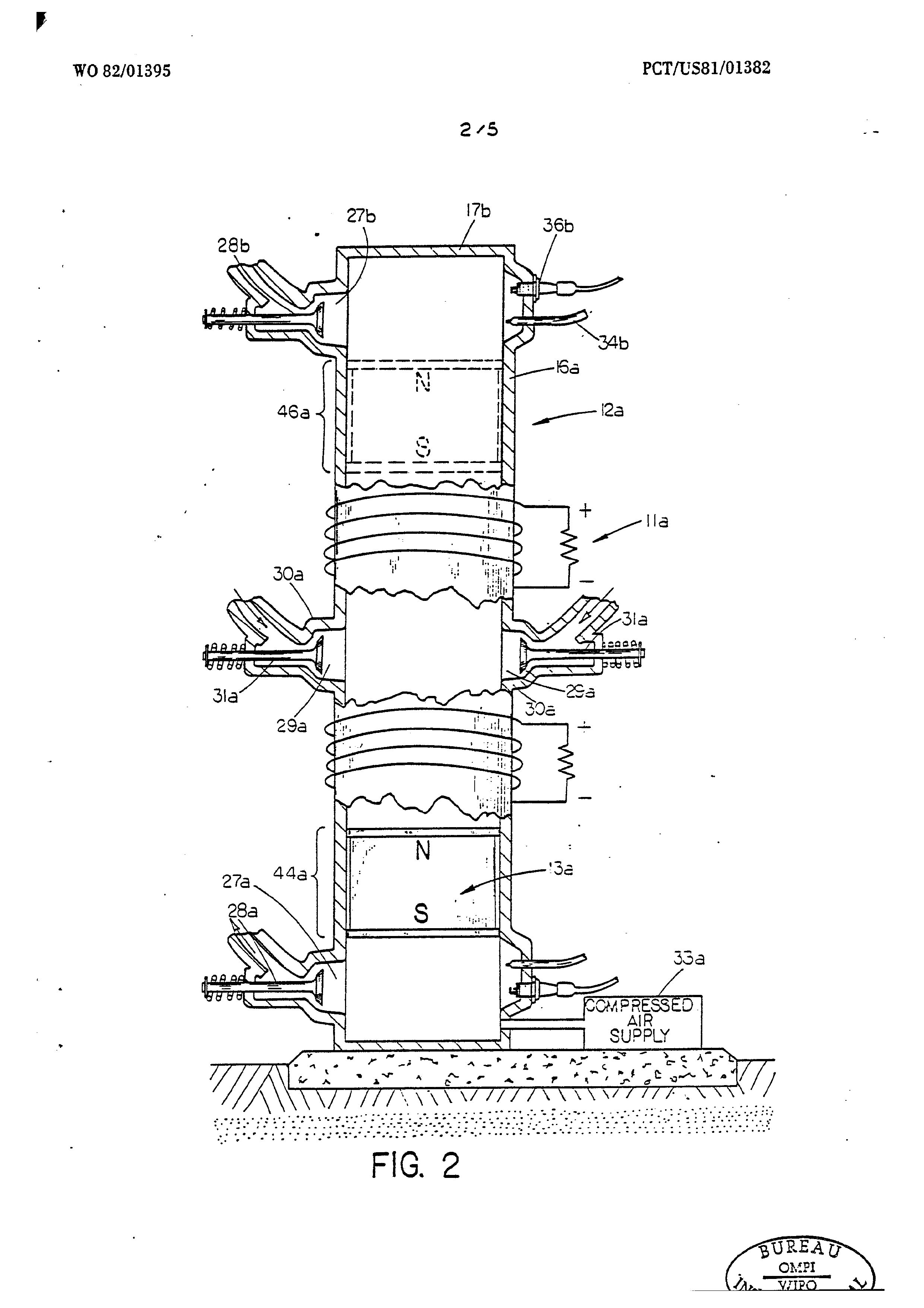

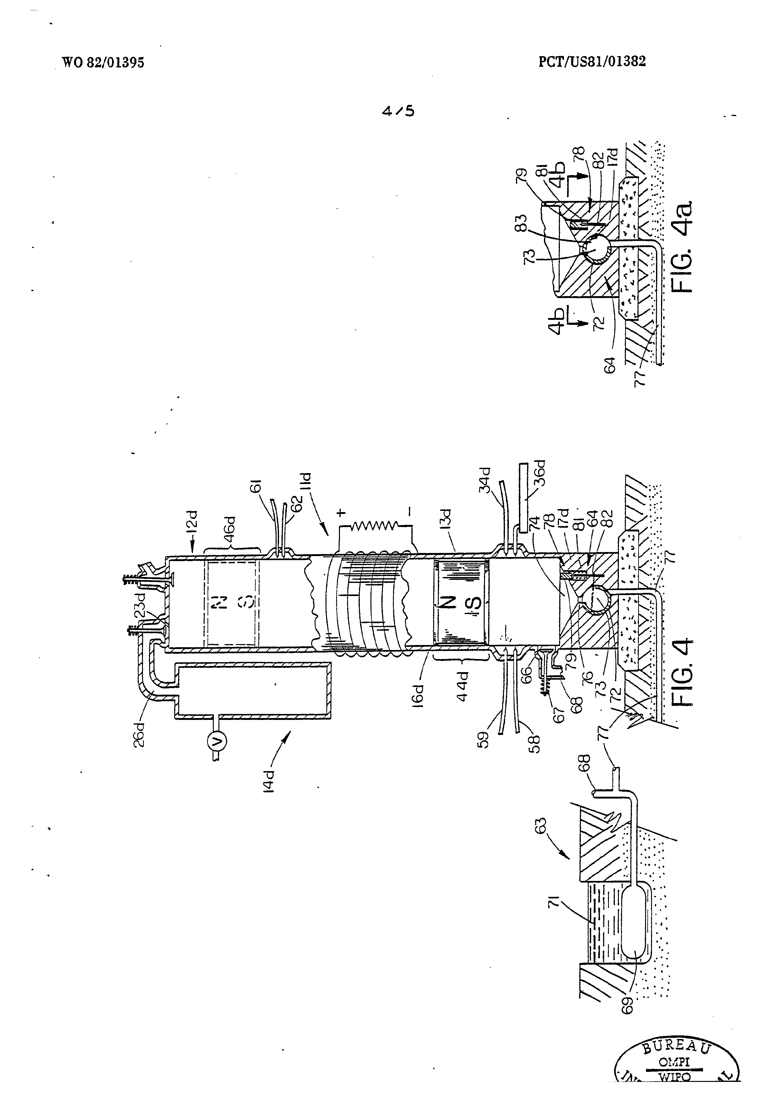
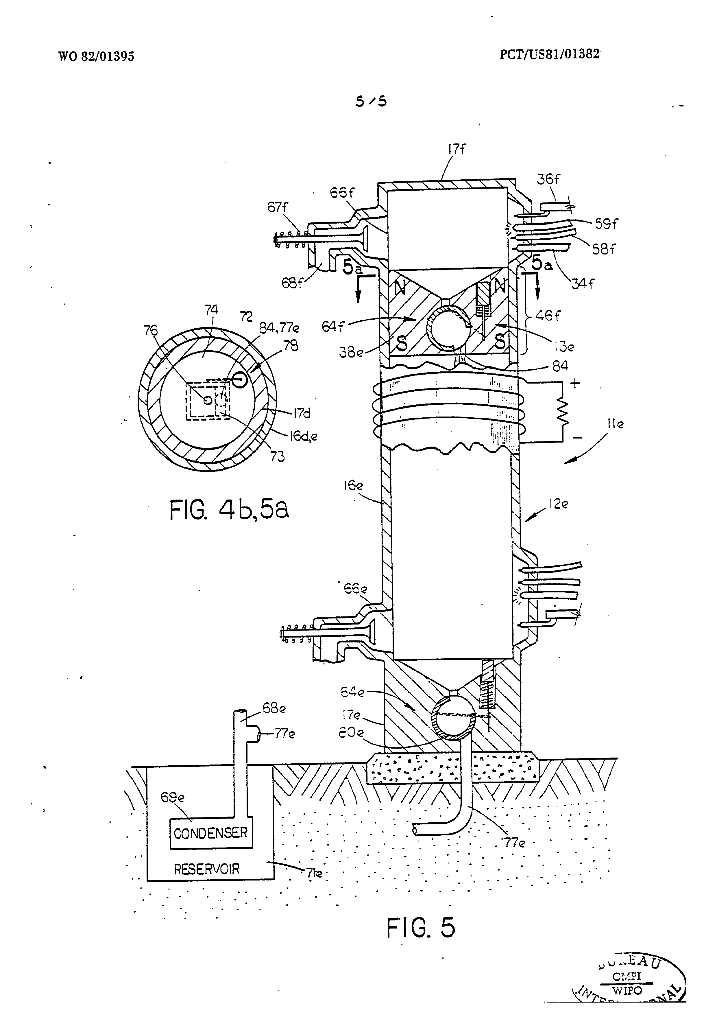
Fig. 1 is a diagrammatic fragmentec, cross-sectional side view of the preferred embodiment wherein a Grive assembly comprising an air reservoir is shown;
Fig. 2 is a diagrammatic fragmented, cross~sectional side view of an alternate embodiment wherein fuel injecting, igniting and exhaust structures are shown at both ends of the cylinder;
Fig. 3 is a diagrammatic fragmented, cross-sectional side view of an alternate embodiment wherein a structure for vaporizing and expanding a liquid by concentrated solar energy is shown;
Fig. 4 is a diagrammatic fragmented, cross-sectional side view of an alternate embodiment. wherein structure for burning hydrogen below the piston assembly. and a drain release valve for surplus water is shown; .
Fig. 4a shows the drain release valve of Fig. 4 in its release attitude;
Fig. 4b is a sectional view of the embodiment of Fig. 4 taken through line 4b-4b of Fig. 4;
Fig. 5 is a diagrammatic fragmented, cross-sectional side view of an alternate embodiment wherein structure for burning hydrogen below and above the piston assembly and two drain release valves are shown; and ;
Fig. 5a is a sectional view of the embodiment of Fig. 5 taken through lines 5a-5a of Fig. 5.
Page 48drawing sheetscan →
Page 49drawing sheetscan →
Page 50drawing sheetscan →
Page 51drawing sheetscan →
Page 52scan →
International search report
International Appilcation No PC T/ US 8] / 01382 ~]
I]. CLASSIFICATION OF SUBJECT MATTER (if several classification symbols apply, indicate all) *
According to International Patent Classification (IPC) or toa both National Classification and IPC 8 e ll, FIELDS SEARCHED
Mini ie) tation Searched +
Classification System ; ; Classification Symbol
Documentation Searched other than Mini ia]
to the Extent that such Documents are Included in the Fields Searched &
Hil. DOCUMENTS CONSIDERED TO BE RELEVANT i+
Category * Gltation of Document, 6 with indication, where appropriate, of the relevant passages 27 Relevant to Claim No. 28
07 Nov, 1944, Ostenberg
13 March 1962, Ehrat et al.
, Pescara
11 June 1963, Duncan
* Special categories of cited documents: 15
“A” document defining the general state of the art “P" document published prior to the international filing date but “" earlier document but published on or after the international on or after the priority date claimed filing date “T™ later document published on or aiter the International filing “L” document cited for special raason other than these referred date or priority date and notin conflict with the application, but cited to understand the principle or theory underlying to in the other categori i er categories the invention
“O" document referring to an oral disclosure, use, exhibition or other means “X* document of particular relevance
Iv. certification
Date of the Actual Completion of the International Search 2 Date of Mailing of this International Search Report 2 are)
International Searching Authority } Signature of Authorized Officer 2°
ISA/US , Abhi ¢ act
Farm PCT/ISA/210 (second sheet) (October 1977) Of
Page 53scan →
International Application No. P CT/ US 8] / 01382 ~|
Further information continued from the second sheet
Stengel _ =
Smith — a ' SmTth et. al. | | ne
GurtTer 7
Konig ° So vo] OBSERVATIONS WHERE CERTAIN CLAIMS WERE FOUND UNSEARCHABLE?° _.
This international search report has not been established In respect of certain claims under Article 17(2) (a} for the following reasons: 17] Claim numbers , because they relate to subject matter12 not required to be searched by this Authority, namely:
2] Claim numbers. , because they relate to parts of the international application that do net comply with the prescribed requirements to such an extent that no meaningful International search can be carried out 15, specifically:
vi] OBSERVATIONS WHERE UNITY OF INVENTION IS LACKING 11
This International Searching Authority found multiple inventions In this Iniernational application as follows:
1] Asail required additional search fees were timely paid by the apglicant, this international search report covers all searchable claims of the international application.
2C4 As only some of the required additional search fees were timely paid by the applicant, this international search report covers only those claims of the International application for which fees were paid, specifically claims:
aC] No required additional search fees were timely paid by the applicant, Consequently, this international search report Is resiticted to the invention first tloned in the claims; it Is covered by claim numbers:
Remark on Protest oO The additional search fees were accompanied by applicant's protest, oO No protest accompanied the payment of additional search fees,
Form PCT/ISA/210 (supplemental sheet (2)) (October 1977)
thet
Page 54scan →
International Application No. PCT/ US 8] /0] 3 82
I. DOCUMENTS CONSIDERED TO BE RELEVANT (CONTINUED FROM THE SECOND SHEET) Category * | Citation of Document, !* with indication, where appropriate. of the relevant passages !7 | Relevant to Claim No 28
Shinn
Cavallo .
Form PCTNSA/210 (extra sheet) (June 1980)
Provenance
- Collection
- Patents citing this work
- Pages
- 54
- Method
- pdftoppm 300dpi + tesseract 5 (eng)
- Patent office record
- patents.google.com →
- Source
- Google Patents citing-documents table
- Assignee
- Donald C Bucknam
- Published
- 1982-04-29
- Transcribed from
- patentimages.storage.googleapis.com →