

patent · US4399368A
Power plant and process utilizing gravitational force
16 August 1983
Text
Page 1bibliographic recordscan →
United States Patent (19)
Bucknam
54 POWER PLANT AND PROCESS UTILIZING
GRAVITATIONAL FORCE
76 Inventor: Donald C. Bucknam, 2124 S. 110th St., Omaha, Douglas County, Nebr.
Related U.S. Application Data 63 Continuation-in-part of Ser. No. 197,314, Oct. 15, 1980. 51 Int. Cl. ................................................ FO3G 7/02 52 U.S. C. ................................... 290/1 R; 60/641.8;
1,544,010 6/1925 Jordan ............................... 123/46 E.
Primary Examiner-J. V. Truhe
Assistant Examiner-Shelley Wade
Attorney, Agent, or Firm-Henderson & Sturm
A power plant and process for converting gas expand ing and contracting energy sources into useful forms of energy and utilizing gravitational force, wherein a pis ton containing a magnet and able to fall within an en closed cylinder, having a non-magnetically-responsive center portion surrounded by an induction coil is re peatedly impelled upwards thereby inducing an alter nating electric current in the coil. In the first alternate embodiment, concentrated solar energy is directed onto a liquid in the bottom of the cylinder to provide an expanding gas beneath the piston. As the piston moves upwards within the cylinder, compressed air is pumped into a reservoir, after which it is available to serve as a source of stored energy. A rotary diversion valve di rects hot vapor and liquid first, between a separate vapor and water reservoir and the cylinder, in order to provide vapor for a bounce chamber beneath the piston and then, to a remote cooled condenser, in order that the vapor may be condensed apart from the cylinder as the piston is free falling. The second alternate embodi ment varies from the first in that liquid is vaporized above the piston in order to compress air or pump water below it. The third alternate embodiment utilizes steam and vacuum to impel a piston both up and down and has no compressed air reservoir.
31 Claims, 6 Drawing Figures
Drawings
Page 2drawing sheetscan →
Page 3drawing sheetscan →
Page 4drawing sheetscan →
Page 5drawing sheetscan →
Page 6scan →
voir is included for the provision of an additional source
POWER PLANT AND PROCESS UTILIZING of energy in the form of compressed air produced by GRAVITATIONAL FORCE the upward motion of the piston in the cylinder, said compressed air also being available to pneumatically
BACKGROUND OF THE INVENTION 5 power the rotary valve.
This application is a continuation-in-part of applica The second alternate embodiment varies from the tion Ser. No. 197,314, filed Oct. 15, 1980. first in that liquid is vaporized above a piston to com This invention relates generally to power plants and press air or pump water below it. The piston is lifted by processes for converting energy from fuel or other O the effect of a vacuum above it created by a remote sources for expanding or contracting gases into useful liquid condenser. The third alternate embodiment alter forms of energy which incorporate enclosed expansion nately utilizes steam on one side of a piston and a vac chambers, wherein gases expand or contract anterior to uum on the other for both lifting and lowering the pis a piston slidably operable within a cylinder and more ton. No compressed air is produced. particularly to such processes and devices which do not 15 An object of the present invention is to provide a require mechanical means of transferring the energy process for converting energy into useful forms without from the piston or a structure such as a flywheel to employing expensive, heavy and dangerous moving serve as a reservoir of potential and kinetic energy, parts, such as connecting rods, cranks, crankshafts, and Conventional internal (gas) or external (steam) con flywheels.
bustion engines have long been employed to convert Another object of the invention is the economic con fuel energy into various forms of stored energy or to version of solar energy into electrical energy regardless operate moving apparatus. Such devices have tradition of the size of the device. ally employed mechanical means of transferring the Still another object of the invention is to convert energy such as connecting rods, cranks, and crank waste industrial steam and geothermal steam into elec shafts. Also, they generally require a flywheel of trical energy.
greater or lesser affect depending upon various factors, 25 A further object of the invention is to circumvent the such as the number of pistons, the massiveness of engine limits imposed by mass, intertia, momentum, wear, parts, and the requirements for smooth and constant maintenance, and manufacturability of the parts. flow of energy. In addition, other conventional parts A still further object of the invention is to convert are required, such as piston pin bearings, all needing solar lubricating means. Also, the momentum acquired by the higherenergy 30 into compressed air or to pump water to elevations for use as a supplemental source of piston must be cancelled by the crank at the end of stored energy.
every stroke. Still further additional objects are to eliminate in If the conventional device employs internal combus power plants costly and massive parts, reduce the con tion, either a crankcase or turbine is required. If it uses external combustion, a burner, boiler, turbine and 35 sumption
Yet of fuel, and reduce pollution.
another object is to provide a simpler power smokestacks are needed, all of the latter are dispensed plant, less expensive with in the present invention. To meet demands for solar based energy. to build and operating solely on strength and stress, such auxiliary parts require addi tional materials, all of which reduce the ratio of energy Yet a further object of the invention is to utilize space available to perform work to the fuel consumed. Corre 40 occupied by the secondary parts of a conventional en spondingly, downtime for maintenance and repairs is gine for the principle parts of the electrical energy gen reduced by the present invention. Furthermore, the erating parts of the present invention. present invention is not subject to the size limitations Other objects, advantages and novel features of the governed by the strength and stress withstanding prop present invention will become apparent from the fol erties of available materials required by large scale 45 lowing detailed description of the invention when con power plants designed to produce great quantities of sidered in conjunction with the accompanying draw energy. lings.
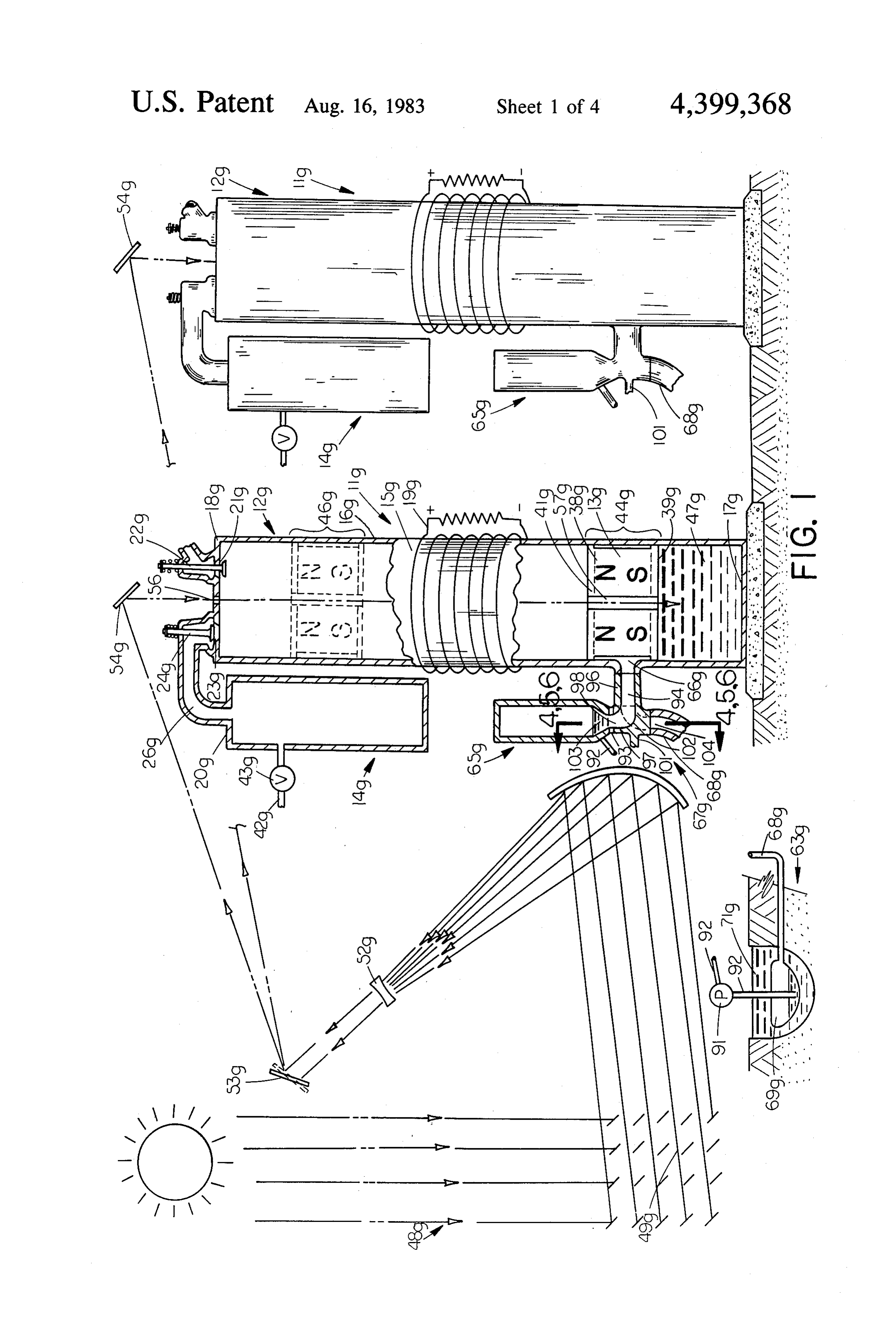
SUMMARY OF THE INVENTION BRIEF DESCRIPTION OF THE DRAWINGS A piston containing a magnet is repeatedly impelled 50 FIG. 1 is a diagramatic, fragmented, cross-sectional upwards within an enclosed cylinder having a load-con side view of the first alternate embodiment wherein a nected electrical conductor coil surrounding its center structure for vaporizing and expanding a liquid below a portion. The first alternate embodiment utilizes concen piston by concentrated solar energy, a remote cooled trated solar energy as a source of heat energy by direct vapor condensor and a separate hot liquid and vapor ing it through a transparent structure in the upper end 55 reservoir are shown;
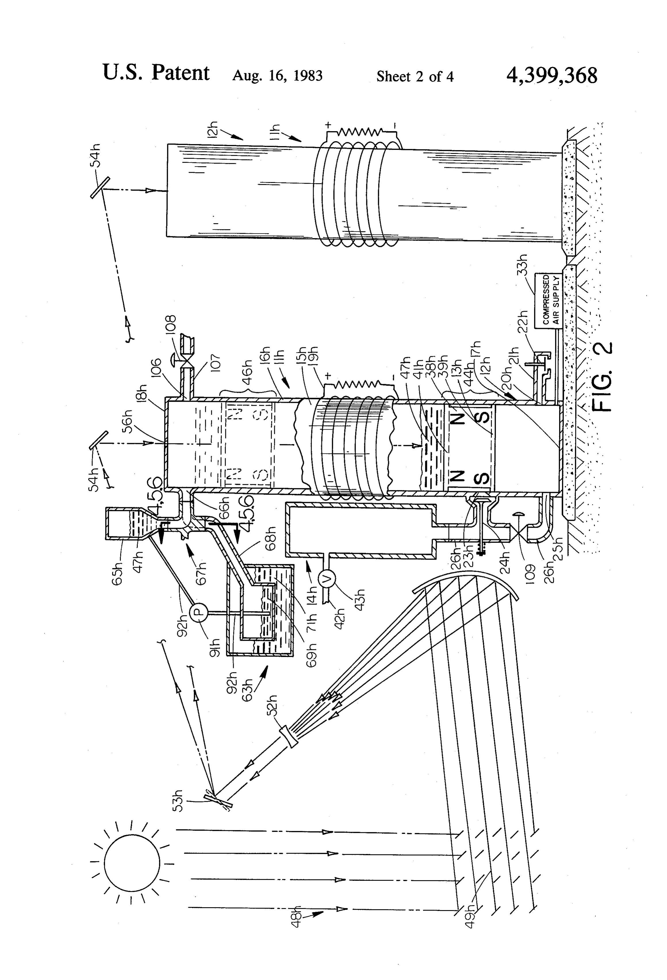
of the cylinder and a transparent core in the piston onto FIG. 2 is a diagramatic, fragmented, cross-sectional a black colored liquid in its lower end so that the liquid side view of the second alternate embodiment wherein will vaporize. As the piston reaches the apex position a a structure for vaporizing and expanding a liquid above three-way rotary diversion valve directs the hot vapor a piston by concentrated solar energy, a remote cooled to a separate hot vapor reservoir, partially filled with 60 vapor condensor and a separate hot liquid and vapor the liquid, in order to trap a portion of the vapor for reservoir are shown;
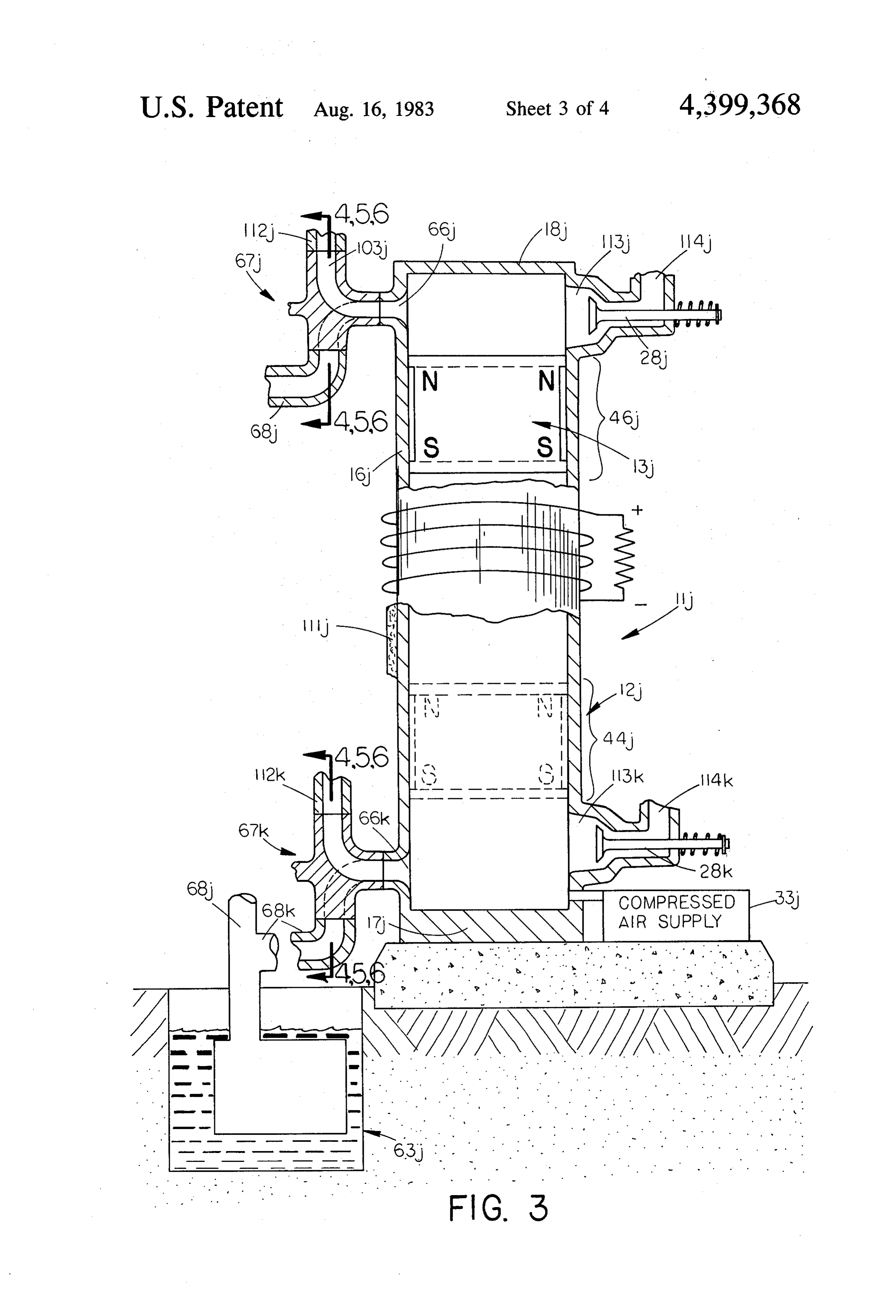
later use as a gas in a bounce chamber beneath the pis FIG. 3 is a diagramatic, fragmented, cross-sectional ton. The rotary valve then directs remaining hot vapor side view of the third alternate embodiment wherein a from the cylinder to a remote cooled liquid condenser structure for utilizing the condensation of steam is included to enhance the speed with which the liquid 65 shown;
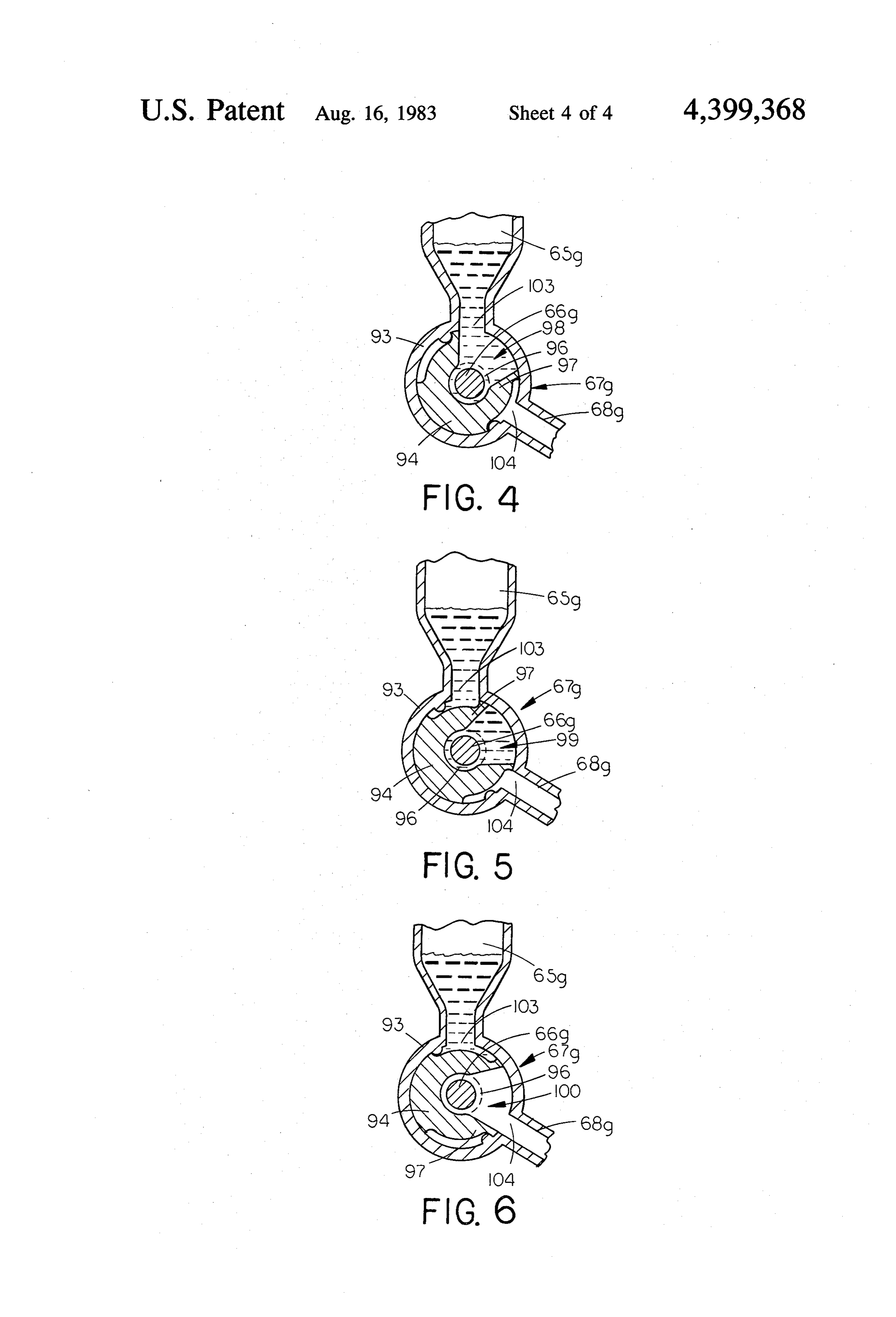
vapor is condensed, and thus the speed with which the FIG. 4 is an enlarged cross-sectional partial view of piston is returned, and to replenish the liquid in the the rotary valve in a position which allows flow be separate reservoir. In addition, a compressed air reser tween the cylinder and the separate hot vapor reservoir 7 of the embodiment of FIGS. 1, 2 and 3, taken along line densed vapor from separate condenser 69g through tube 4-4 of each of said FIGS.; 92 to separate vapor reservoir 65g. FIG. 5 is an enlarged cross-sectional partial view of Rotary diversion valve assembly 67g is comprised of the rotary valve in a position which allows no flow a housing 93 which is a drum shaped hollow cylinder between the cylinder and the interconnected elements having two circular openings 103 and 104 (See FIG. 4), of the embodiments of FIGS. 1, 2 and 3, taken along line a rotatable elbow joint 94 which rides inside of housing 5-5 of each of said FIGS.; and 93 and has an internal conformation which permits one FIG. 6 is an enlarged cross-sectional partial view of leg 96 of the elbow to rotate in sealed conjoinment with the rotary valve in a position which allows flow be port 66g (See FIG. 1) and the other leg 97 to be moved tween the cylinder and the remote vapor condenser of 10 rotationally between three positions. These positions the embodiments of FIGS. 1, 2 and 3, taken along line can be most clearly understood by reference to FIGS. 4, 6-6 of each of said FIGS. 5 and 6 and include a first position 98 where cylinder
Description of the first alternate
12g is connected with vapor reservoir 65g through opening 103 of housing 93 (See FIGS. 1 and 4) and a
EMBODIMENT 15 second position 99 where cylinder 12g is sealed with Referring now to the drawings wherein like refer respect to reservoir 65g and condenser 69g (See FIG. 5) ence numerals designate identical or corresponding and a third position 100 where cylinder 12g is connected parts, the power plant is depicted generally in FIG. 1 at by tube 68g to vapor condenser assembly 63g through 11g and includes a cylinder assembly 12g, a piston as opening 104 of housing 93 (see FIG. 6). The internal sembly 13g, an air reservoir 14g, a liquid vapor con 20 conformation of leg 97 is such that the above relation denser assembly 63g, a separate hot vapor reservoir 65g, ships can be realized by an appropriate rotation of a three-way rotary valve assembly 67g, and a concen elbow joint valve 94. A shaft 101 is affixed to an ex trated solar energy assembly 48g. posed portion 102 of elbow joint 94 located opposite its The cylinder assembly 12g is comprised of a cylinder conjoinment with port 66g for rotation thereof by con wall 16g, and a load-connected electrical conductor coil 25 ventional structure (See FIG. 1). As the present inven 19g surrounding a center portion 15g of the cylinder. tion is operated, compressed air is accumulated in com The center portion 15g of the cylinder 16g must be of a pressed air reservoir 14g in a manner to be disclosed non-magnetically-responsive material of either metal or hereinafter, and said compressed air supply may be used ceramic. By properly supporting the upper half of the to supply pneumatic power to pistons to operate cranks cylinder, the walls of the central part of the cylinder 15g 30 (not shown) for turning shaft 101. between the ends may be relatively thin, thus permitting Cylinder assembly 12g has a black colored liquid 47g the coil to be in close proximity with the magnetic contained beneath a piston assembly starting position piston. As compared to the center portion 15g, a portion 44g and adjacent its lower end wall 17g. Concentrated near the lower end wall 17g, is subject to higher de solar energy assembly 48g for vaporizing the black mands for structural strength, heat resistance, and pres 35 colored liquid 47g includes conventional heliostat re sure resistance. Materials with appropriate properties flectors 49g, parobolic concentrator-reflector 51g, con are well known and are required for the device to func cave lens 52g, movable reflector 53g, stationary reflec tion properly. tor 54g, solid transparent portion 56g of upper end wall The piston assembly 13g is slidably operable within 18g, and solid transparent core portion 57g of the piston the cylinder assembly 12g and includes an intermediate 40 assembly 13g.
bar magnet in the form of a magnetic disc 38g which has Additional complexes of cylinder assembly 12g, pis a lower ceramic plate 39g and an upper ceramic plate ton assembly 13g, and air reservoir 14g may be synchro 41g secured to its lower and upper ends, respectively, to nized with a single solar energy assembly 48g so as to serve as piston rings. The polar axis of the bar magnet produce a more constant supply of converted energy 38g is oriented so that it coincides with the longitudinal 45 and to maximize the use of sunlight. Although an air axis of the cylinder assembly 12g. The lower and upper reservoir 14g is shown for each power plant complex, a plates 39g and 41g, may be of other non-magnetically single air reservoir could serve several such complexes. responsive material such as copper or aluminum. Likewise, individual vapor condensing assemblies 63g The upper end wall 18g of the cylinder assembly 12g could be provided for each power plant complex, rather has an inlet port 21g with a spring-biased valve 22g 50 than a single one to serve several such complexes as mounted therein and an outlet port 23g with a spring shown.
biased valve 24g mounted therein which is connected plant The process of converting energy with the power by a tube 26g to first end 20g of air reservoir 14g. Air 1g includes a starting phase and a repeating cycle reservoir 14g has a take-off tube 42g with check valve phase. Prior to initiating the starting phase, the piston 43g mounted therein. As will be noted hereinafter, air 55 assembly i3g is held at rest at starting position 44g by reservoir 14g may be utilized as a supplementary source the compressive support of liquid 47g. The starting of stored energy by tapping compressed air through phase is initiated by the vaporization of liquid 47g when tube 42g. In addition, storing and releasing energy in concentrated solar energy is directed upon it. The black this manner further provides for fluctuations in load. colored liquid 47g is thereby vaporized forming an ex Adjacent the lower end wall 17g, located in cylinder 60 panding gas which lifts the piston assembly 13g to apex wall 16g is inlet/outlet port 66g (See also FIG. 4) having position 46g near upper end wall 18g. During this opera a rotary diversion valve assembly 67g mounted therein tion, the column of air above piston assembly 13g passes and connected to separate hot vapor reservoir 65g and through outlet port 23g and tube 26g into air reservoir through tube 68g to separate condenser 69g of vapor 14g creating a supply of compressed air therein. After condensing assembly 63g. Vapor condensing assembly 65 vapor expanding beneath piston assembly 13g has lifted 63g includes separate condenser 69g which contains a it to apex position 46g, in the case where a single power near perfect vacuum, chilled water 71g which envelops plant complex is synchronized with one or more others, condenser 69g, and liquid pump 91 which returns con movable reflector 53g of solar energy means 48g directs 8 concentrated solar energy to another stationary reflec chamber at the bottom of the cylinder which will deter tor 54g of another complex, allowing piston assembly the falling piston from ever physically striking the liq 13g to free fall as black colored liquid 47g thereafter uid. Were the piston to suddenly free fall against the begins to cool and condense. Otherwise, the position of liquid upon the setting of the sun or sudden moving in of movable reflector 53g of solar energy means 48g would cloud cover, the shock would undoubtedly do great be shifted at appropriate points in time so as to discon damage to the cylinder unless other cushioning steps tinue any unneeded vaporization of liquid 47g or for the were taken. It is important that cylinder assembly 12g purpose of lifting piston assembly 13g to apex position be well insulated, in particular in the area near lower 46g. end wall 17g, in order to keep it hot at all times for the As piston assembly 13g free falls toward starting posi 10 purpose of avoiding the condensation of the hot vapor tion 44g, it will pull open valve 22g permitting fresh air into black colored liquid which would occur if it were to enter through inlet port 21g and allow valve 24g to to come in contact with a cold cylinder wall. The more close, sealing off the supply of compressed air now in of the condensation which occurs in the separate con air reservoir 14g. In order to hasten the return of piston denser 69g, the more of the sun's energy will be con assembly 13g to starting position 44g, and due to the 5 verted into forms which can be stored and used. length of time it would take for the vaporized liquid in It is also possible to direct the solar beam into the cylinder 12g to condense therein, the heated liquid bounce chamber at a point prior to when piston assem vapor is released through port 66g prior to the initiation bly 13g has returned to starting position 44g there by of the descent of piston assembly i3g. increasing the pressure of the hot vapor in the bounce This result is accomplished by valve assembly 67g, 20 chamber to provide greater protection against the pis which opens to first position 98 to permit a certain ton assembly 13g striking the liquid 47g. amount of vapor to escape from the bottom of cylinder Each time the piston assembly 13g begins its ascent in assembly 12g into the separate hot vapor reservoir 65g. a repeating cycle condensed vapor from remote con This occurs before the piston reaches its apex position denser 69g is pumped by pump 91 through tube 92 into 46g while the vapor still contains considerable pressure. 25 the bottom of the vapor reservoir 65g and allowed to The amount of vapor permitted to escape into reservoir accumulate there until the piston assembly again 65g is based on its future use as a medium for a bounce reaches apex position 46g. To insure that the condensed chamber beneath starting position 44g. After this quan vapor being pumped from remote condenser 69g does tity of vapor has been stored in reservoir 65g, valve not enter reservoir 65g at a temperature which will assembly 67g moves to the third position 100 where the 30 reduce the vapor pressure in reservoir 65g, tube 92 remaining vapor is permitted to escape through tube passes through a thermostatically controlled heat ex 68g into the cooled remote condenser 69g which always change structure (not shown).
contains a near perfect vaccum. Thus, a vacuum be Compressed air reservoir 14g makes available an ad neath the piston is provided for a longer period of time, ditional supply of high pressure gas which, in an emer thereby assisting gravity in returning the piston to its 35 gency, could be piped to a safety valve beneath starting starting position 44g. position 44g to bolster the bounce chamber medium When piston assembly 13g has reached a position (structure is not shown).
about mid-way down the cylinder, valve assembly 67g To discontinue the operation of the power plant returns to the first position 98, allowing the vapor and when desired, as well as toward the end of each day, liquid to return from separate hot reservoir 65g to cylin 40 valve assembly 65g is prohibited from moving from first der assembly 12g beneath piston assembly 13g in order position 98 or second position 99 to the third position to serve as a bounce medium for piston assembly 13g as 100 thus preventing vapor from escaping to the remote it approaches starting position 44g. Also in this manner condenser assembly 63g. As the vapor now trapped an adequate amount of dark colored liquid is returned to below piston assembly 13g loses its heat through cylin the cylinder 12g for the repeat cycle. 45 der wall 16g, the piston will gradually settle upon the Prior to piston assembly 13g returning to starting liquid to be ready for the next starting phase. position 44g, and as the black colored liquid 47g remain It is believed that the method for producing and di ing in cylinder assembly 12g has begun to condense and recting a beam of concentrated solar energy may not be mix with returning black colored liquid 47g from sepa generally known to those skilled in the pertinent art rate vapor reservoir 65g, concentrated solar energy 50 and, therefore, the following explanation is included means 48g is re-directed to the stationary reflector 54g herein. Sunlight is reflected by heliostat 49g, which is in order that the black colored liquid reaccumulating in comprised of a large array of steered mirrors. As the sun the bottom of cylinder assembly 12g is maintained at moves across the sky, the heliostat 49g directs the beams whatever temperature above its boiling point is desired to a parabolic concentrator-reflector 51g which is with respect to operational requirements. 55 fixedly mounted and which directs the collection of Before piston assembly 13g has reached its starting beams through a concave lens 52g. The lens 52g causes position 44g, rotary diversion valve assembly is moved the collection of beams to become a concentrated paral to the second position 99, thus sealing off the cylinder lel beam and is located so as to direct this beam onto a beneath piston assembly 13g and the first repeating movable mirror 53g. Mirror 53g is controlled by sole phase is initiated by the revaporization of the black 60 noid or hydraulic means to alternately direct the con colored liquid 47g. The temperature of the black col centrated solar energy to the several stationary mirrors ored liquid 47g is that of the surrounding environment 54g where the beam is alternately reflected through only just prior to the starting phase and is higher during transparent portion 56g of upper end wall 18g and trans any repeating phase. Thus, the velocity of the ascending parent core portion 57g of piston assembly 13g onto the piston may be varied by controlling the operating tem 65 black colored liquid 47g in each cylinder assembly 12g. perature of the black colored liquid 47g. In addition to the material requirements set forth There must be enough vapor from reservoir 65g hereinabove, the transparent portion 56g in upper end above the water in the cylinder to provide a bounce wall 18g and the transparent core 57g in piston assembly
Page 9scan →
13g may be of glass, crystal, or a suitable plastic which whenever the pressure therein is below atmospheric are well known in the art. A suitable agent for coloring pressure. Whenever the in-flow of air through one-way the liquid 47g black is graphite containing some oil atmospheric valve 22h stops, it is closed by the effect of lubricant. Electronic timing devices (not shown) will gravity.
maintain sequential control of the movable mirror 53g, 5 Also located in cylinder wall 16h adjacent to lower and the timing of each step of the process is controlled end wall 17h is a second inlet port 25h which is con by electronic timing devices through conventional nected by tube 26h to first end 20h of air reservoir 14h. switches operated by solenoids or by hydraulic, pneu A gate valve 109 is located in tubing 26h adjacent to matic or mechanical controls where necessary. Elec inlet port 25h which is opened as required to maintain tronic timing devices which have provisions for adjust air pressure below piston means 13h to keep it at a start ments to allow for variations in sunlight, atmospheric ing position 44h.
pressure, temperature, etc., are well known; and, under An outlet port 24h is located in cylinder wall 16h a a given set of parameters, gravity being constant, once short distance above lower end wall 17h, inlet port 21h an appropriate timing sequence is determined, the en and inlet port 25h, Outlet port 24h has a spring-biased ergy converting device 11g will continue the repeating 15 valve 27h mounted therein which connects outlet port cycle. 24h to tube 26h at a point between first end 20h of air Solar energy will be converted into electrical energy reservoir 14h and gate valve 109. Also, air reservoir 14h as the magnetic forces of the magnetic disc 38g pass by has a take-off tube 42h with check valve 43h mounted the electrical conductor coil 19g, thereby inducing an therein. As in the first alternate embodiment, air reser electric current. Means for converting the alternating voir 14h may be utilized as a supplementary source of current thus produced into suitable frequencies and stored energy by tapping compressed air through tube voltages for transmission over long distances are well 42h.
known and not shown herein. Also, stored energy is Compressed air supply 33h supplies cylinder assem available in the form of compressed air by opening bly 12h with a quantity of pressurized air which sup valve 43g mounted in take-off tube 42g. 25 ports piston assembly 13h at or above starting position
Description of the second alternate
44h. A supply of dark colored water 47h is located atop piston assembly 13h as well as being contained in water
Referring now to FIG. 2, an alternate embodiment of At the beginning of the process of converting energy the power plant is depicted generally as 11h and in 30 with power plant 11h, piston assembly 13h is held at or cludes a cylinder assembly 12h, a piston assembly 13h, above starting position 44h by compressed air beneath an air reservoir 14.h, a steam condensing assembly 63h, it. A cycle of the process is initiated by first vaporizing a hot water and vapor reservoir 65h, a rotary diversion a portion of the dark colored liquid atop piston assem valve assembly 67h, and a concentrated solar energy bly 13h and then venting excess water vapor above assembly 48. This embodiment differs primarily from 35 piston assembly 13h to the atmosphere by opening gate the preferred embodiment in that liquid is vaporized valve 108. Gate valve 108 is closed before any air enters above the piston assembly 13h rather than below it. This therethrough into cylinder assembly 12h. Valve assem difference eliminates the need for a transparent core bly 67h is then moved from second position 99h (see portion in the piston assembly 13h. Except as noted FIG. 5) which allows no flow, to third position 100h hereinbelow, power plant 11h has parts parallel to those 40 (see FIG. 6) which connects the space above piston of power plant 11g and said parts are designated by assembly 13h to steam condensing assembly 63h. The corresponding numerals with the letter "h" appended water vapor above the piston assembly 13h will then thereto. flow out as it is condensed, thereby creating a relative The fit between the internal diameter of cylinder 16h vacuum above piston assembly 13h. The pressure below and ceramic plates 39h and 41h must be lose enough to 45 piston assembly 13h is not allowed to fall below atmo prevent any water 47h above piston 13h from flowing spheric by one-way valve 23h. The resulting pressure into the space below it. The piston must be constructed difference will cause piston assembly 13h to rise. Valve so that it weighs less than 14.7 pounds per square inch of assembly 67h is changed to second position 99h at the horizontal cross-sectional area, since atmospheric pres appropriate moment for causing piston assembly 13h to sure will be utilized for raising the piston as described in 50 stop at an apex position 46h, which is a short distance detail below. below inlet/outlet port 66h. The space within cylinder Adjacent the upper end wall 18h, located in cylinder assembly 12h below piston assembly 13h is at this point wall 16h is an inlet/outlet port 66h having a rotary occupied by air at atmospheric pressure that has been diversion valve assembly 67h mounted therein. Since admitted by one-way valve 22h.
rotary diversion valve assembly 67h is of a structure 55 Before a piston lowering step occurs, valve assembly identical to the rotary diversion valve assembly 67g 67h is changed to first position 98h (see FIG. 4) in order utilized in the first alternate embodiment, FIGS. 4, 5 to replenish the amount of water 47h above piston as and 6 and parallel elements therein designated by nu sembly 13h by allowing water to flow from water reser merals having either the letter "g" or no letter ap voir 65h through valve assembly 67h into the space pended thereto will be referred to as though the letter above piston assembly 13h. When the required amount "h' was instead so appended. Also located in cylinder of water 47h is inside cylinder assembly 12h above pis wall 16h adjacent the upper end wall 18h is an outlet ton assembly 13h, valve assembly 67h is then moved port 106 which is connected by a tube 107 to a gate back to position 99h which allows no flow. valve 108 which is exposed to atmospheric pressure. The step of lowering piston assembly 13h is affected Adjacent the lower end wall 17g, located in cylinder 65 by vaporizing water 47h above piston assembly 13h by wall 16h is inlet port 20h. Inlet port 20h is connected by directing a concentrated beam of solar energy upon it. a tube 21h to a one-way atmospheric valve 22h which The resulting increase in pressure above piston assem allows air to flow into the lower section of cylinder 12h bly 13h forces it downwards, compressing the column 10 of air below it. When the air below piston assembly 13h The entire cylinder assembly 12j is covered by insula exceeds the pressure inside air reservoir 14h, spring tion 81j in order to prevent the condensation of low biased valve 24h opens, allowing the air to flow through temperature steam that may be used by power plant 11i outlet port 24h and tube 26h into air reservoir 14h, Piston assembly 13j is designed for minimum weight in creating a supply of compressed air therein. This flow order to minimize mechanical wear and to minimize the of air into air reservoir 14h is stopped when piston as effort required to lift it by low pressure steam. sembly 13h reaches starting position 44h where piston Adjacent the upper end wall 18i, located in cylinder assembly 13h blocks outlet port 23h and the compres wall 16i, is an outlet port 66j which has first rotary sive support of the air below piston assembly 13h halts diversion valve assembly 67i mounted therein. Since the downward movement of piston assembly 13h. At 10 rotary diversion valve assembly 67i is of a structure this point the concentrated solar energy is directed identical to the rotary diversion valve assembly 67g away from power plant 11h and the steam above piston utilized in the first alternate embodiment, FIGS. 4, 5 assembly 13h is vented to the atmosphere as described and 6 and parallel elements designated by numerals above in preparation for another cycle. having either the letter "g" or no letter appended In the case where a single power plant complex is 15 thereto, will be referred to as though the letter "j" was synchronized with one or more others, movable reflec instead so appended. However, port 103j of rotary di tor 53h of solar energy means 48h directs concentrated version valve assembly 67j is connected to tubing 112 solar energy to another stationary reflector 54h of an which is vented to atmosphere rather than port 103i other complex after piston assembly 13h reaches start being connected to separate vapor reservoir 65g as in ing position 44h at the end of the lowering step. Other 20 the first alternate embodiment. Also located in cylinder wise, the position of movable reflector 53h of solar wall 16jadjacent to upper end wall 18i, is an inlet port energy assembly 48h would be shifted at appropriate 113 with spring biased inlet valve 28i Tubing 114 con points in time so as to discontinue any unneeded vapori nects inlet port 113 to a heat exchanger or other source zation of water for the purpose of lowering piston of steam which may be either industrial waste steam or means 13h to starting position 44h. 25 geothermal steam, for example. A corresponding set of When the power plant is not in use, the compressed ports and valves are located in cylinder wall 16i adja air in air reservoir 14g can be utilized in addition to cent to lower end wall 17i which are designated by the compressed air supply 33h to prevent piston assembly appended letter "k".
13h from settling down onto lower end wall 17h by At the beginning of the process of converting energy opening gate valve 109 as required. 30 with power plant 11j, piston assembly 13i is held at or
Description of the third alternate
above starting position 44j by steam pressure supplied
Embodiment
through port 113k. A cycle of the process is initiated by first venting excess steam pressure above piston assem
Referring now to FIG. 3, another alternate embodi bly 13i to the atmosphere by moving upper valve assem ment of the power plant is depicted generally as 11j and 35 bly 67i to first position 98j (see FIG. 4) which connects includes a cylinder assembly 12i, a piston assembly 13i, the interior of cylinder assembly 12i above piston 13j to a steam condensing assembly 63i, and two rotary diver the atmosphere through tubing 112. Rotary diversion sion valve assemblies 67i and 67k. This embodiment valve 67i is then moved to third position 100j (see FIG. differs primarily from the first alternate embodiment in 6) which connects the space above piston assembly 13i that the pressure difference for raising and lowering 40 to steam condensing assembly 63j through tube 68i piston assembly 13j is maintained in part from a source Valve 28k is then opened allowing steam to flow into of low pressure steam exterior to the power plant 11ji the space below piston assembly 13i. The resulting pres This difference eliminates the need for a liquid within sure difference created by the steam below piston as cylinder 12i that is vaporized by an exterior source of sembly 13j and the relative vacuum above piston 13i energy. Except as noted hereinbelow, power plant 11j 45 then causes it to rise towards the top of power plant 11j. has parts parallel to those of power plant 11g and said Shortly before piston assembly 13j reaches the top, parts are designated by corresponding numerals with valve assembly 67j is moved to position 99j (see FIG. 5), the letter "j" appended thereto. allowing no flow therethrough, and valve 28j is opened At present, vast amounts of low pressure steam from long enough to allow a sufficient quantity of steam into geothermal or other sources are not being utilized be 50 the space above piston assembly 13j to serve as a bounce cause there has been no economical way devised to chamber medium. Thus, mechanical contact between utilize such steam. If such steam is at atmospheric pres piston assembly 13j and upper end wall 18j is prevented. sure, 14.5 PSI, it is simply allowed to escape. However, This quantity of steam will cause piston assembly 13j to if it is contained within a cylinder and allowed to con halt at an apex position 46i. Also, at the moment valve dense on one side of a piston, given enough piston area, 55 28i is opened, valve 28k is closed, since steam is no considerable power can be converted from it. This em longer required to lift piston assembly 13i bodiment discloses a way of utilizing such a source of The step of lowering piston assembly 13j is effected energy. by first venting the steam below piston assembly 13j to If the low pressure steam comes from geothermal the atmosphere by moving lower rotary valve assembly sources it may contain chemicals which form scale and 60 67k to first position 98k (see FIG. 4) which connects the plug pipes and valves. Also, it might contain inert gases, interior of cylinder assembly 12i below piston assembly such as carbon dioxide or hydrogen sulfide which, since 13j to the atmosphere through tubing 112k. Rotary they would not condense, would quickly fill the sepa valve assembly 67k is then moved to third position 100k rate condenser, thus rendering it useless for creating a (see FIG. 6) which connects the space below piston vacuum. In such instances, a thermostatically con 65 assembly 13j to steam condensing assembly 63j through trolled heat exchanger (not shown) would be employed, tube 68k. Valve 28j is then opened allowing steam to in order that only steam generated from pure water flow into the space above piston assembly 13j. The would enter the device. resulting pressure difference created by the steam above 11 piston assembly 13j and the relative vacuum below lowering said piston means to said starting position, piston assembly 13j, combined with the weight of piston including the steps of:
assembly 13j, causes it to fall towards the bottom of discontinuing the directing of the concentrated power plant 1j. Shortly before piston assembly 13i solar beam, thereby allowing the vapor to con reaches the bottom, valve assembly 67k is moved to 5 dense and leave a vacuum below the piston position 99k (see FIG. 5), allowing no flow there means, and allowing said spring-biased valve in through and valve 28k is opened long enough to allow the outlet port to close and a spring-biased valve a sufficient quantity of steam into the space below pis in an inlet port in the upper end to open in order ton assembly 13i to serve as a bounce chamber medium. to admit a charge of fresh air; Thus, mechanical contact between piston assembly 13i 10 allowing a portion of the vapor to escape from and lower end wall 17i is prevented. This quantity of beneath the piston means in the cylinder means steam also serves to hold piston assembly 13j in starting to a separate hot reservoir partially filled with position 44i in order that another cycle might be initi said liquid by a valve means for diverting the ated as described above. Also, at the moment valve 28k vapor when the piston means reaches the apex is opened, valve 28j is closed, since steam is no longer 15 position;
required to lower piston assembly 13i. allowing any remaining liquid or liquid vapor to When power plant 11j is not in use, compressed air escape from beneath the piston means in the supply 33j could be utilized in lieu of steam pressure to cylinder means to a remote cooling condenser prevent piston assembly 13j from settling down onto containing a near perfect vacuum by the vapor lower end wall 17i by maintaining a sufficient amount of 20 diverting valve means before the piston means pressure beneath piston assembly 13, to hold it at start reaches a mid-point between the apex position ing position 44j. Any compressed air so utilized could be and the starting position; purged from cylinder assembly 12j by moving rotary preventing the escape of the vapor beneath the diversion valve 67k to first position 98k (see FIG. 4) and piston into the remote cooling condenser by the opening valve 28k for a suitable period. Also, it should 25 vapor diverting valve means; and be noted that whenever rotary valve assemblies 67i or allowing a portion of the vapor and liquid stored in 67k are utilized for allowing steam to escape to the the separate hot reservoir to return therefrom to atmosphere, they must be reclosed before any air is the cylinder means beneath the piston means by allowed to enter cylinder assembly 12j, as the presence the vapor diverting valve means before the pis of air would interfere with the performance of steam 30 ton means reaches the starting position, whereby condensing assembly 63i a bounce chamber for the falling piston is pro By using a piston assembly of sufficiently low weight, vided and the liquid in the cylinder means is this third alternate embodiment could be modified by replenished; and orienting the cylinder assembly horizontally rather than stopping the downward movement of said piston vertically. Also, it might be feasible to utilize the steam 35 means at said starting position by compressed gas exhausted to atmosphere by this embodiment in other below said piston means, thereby completing a similar power plants to create more electric power. In cycle which can be repeated by starting at the order to limit the deposit of mineral inpurities typically step in which the piston is lifted. found in geothermal steam, it may be desirable to intro duce a heat exchanger to produce steam from pure 40 ing2.the The process as defined in claim 1 further compris step of:
Water.
Obviously, numerous modifications and variations of increasing the vapor pressure beneath the piston the present invention are possible in light of the above means after a portion of the liquid vapor has re teachings. It is therefore to be understood that within turned to the cylinder means from the separate the scope of the appended claims, the invention may be 45 reservoir and before the piston means has returned practised otherwise than as specifically described to its starting position by directing a concentrated therein. solar beam onto the liquid vapor and liquid beneath I claim: the piston means.
1. A process for converting gas expanding energy 3. The processes defined in claim 1 further compris sources into useful other forms of energy, such as induc- 50 ingreplacing the step of:
said liquid in the separate reservoir which ing an alternating current in a coil, comprising the steps of: will be returned to the cylinder means by pumping holding a piston means forming a magnetic field and condensed liquid from the cooling condenser is slidably operable, but otherwise unattached, within said separate reservoir.
a substantially enclosed cylinder means at a starting 55 4. The process as defined in claim 3 further compris position near a lower end thereof, by the compres ingkeepingthe step of:
the liquid being pumped from the cooling sive support of the vapor of a liquid in the bottom of the cylinder means, said cylinder means having a condenser to the separate reservoir hot whereby load-connected electrical conductor coil means the pressure therein will not be materially lowered. surrounding it intermediate its ends; 60 5. A device for converting gas expanding and con lifting said piston means to an apex position near the tracting energy sources into useful other forms of en upper end of said cylinder means by vaporizing the ergy, such as inducing an alternating current in a coil, liquid by directing a concentrated solar beam onto comprising:
it, thereby opening a spring-biased valve mounted a liquid and its vapor located in the bottom of a cylin in an outlet port in the upper end of said cylinder 65 der means to support in a starting position near a means in order to transfer the column of air above lower end of the cylinder means a piston means the piston means through a tube into a reservoir forming a magnetic field, said cylinder means also means; having an upper end and a load-connected electri 12 cal conductor coil surrounding it intermediate said load-connected electrical induction coil surround ends thereof; ing it intermediate the ends thereof; a transparent core in said upper cylinder end and valve means connected to an inlet-outlet port in the another in said piston means for permitting a con upper end of the cylinder means, for diverting centrated solar beam to be intermittently directed liquid and vapor from the upper end of the cylinder on said liquid in order to vaporize said liquid for means to a remote cooling condenser for reducing lifting the piston means to an apex position near the the pressure above the piston means or to a makeup upper end of said cylinder means and after con liquid reservoir;
densing, causing said piston means to return to said a first one-way valve mounted in a first inlet port in starting position to complete a cycle; 10 the lower end of the cylinder means for allowing a first spring-biased valve mounted in a first outlet air into the cylinder means when the pressure port in the upper end of the cylinder means for therein falls below atmospheric pressure facilitat allowing the column of air above the piston means ing the lifting of the piston means when there is a to be forced through a connecting tube into a com 15 near perfect vacuum above it; pressed air reservoir means; a transparent core in said upper cylinder end for a spring-biased valve mounted in an inlet port in the permitting a concentrated solar beam to be inter upper end of the cylinder means to allow the piston mittently directed on a liquid located within the means to pull a fresh column of air in above it as it cylinder means above the piston means in order to vaporize said liquid for lowering the piston means concentrated solar beam directing means; to the starting position; a separate hot vapor reservoir partially filled with a second one-way valve means mounted in a first said hot liquid connected by a first tube to a second outlet port in the lower end of the cylinder means outlet port located in said cylinder means beneath for allowing the column of air below the piston the starting position; means to be forced through a tube into a com a cooling condenser containing a near perfect vac 25 pressed air reservoir means; uum connected by a second tube to said second concentrated solar beam directing means; and outlet port insaid cylinder means and by a third means for sequentially timing the directing and dis tube to said separate hot vapor reservoir; continuing directing of the concentrated solar a valve means mounted in said second outlet port for 30 beam onto the liquid.
diverting liquid vapor and liquid between the cyl 11. The device as defined in claim 10 further includ inder means and the separate hot vapor reservoir ing a second said device as defined in claim 10 for inter and from the cylinder means to the remote cooling mittent operation by directing the concentrated solar condenser and for sealing off the cylinder means beam on the liquid in the top of the second device so from both the separate hot vapor reservoir and the 35 that the two-cycle phases of the two devices are one cooling condenser; half phase out of step with each other. means for pumping condensed hot liquid from the 12. The devices as defined in claims 10 or 11 wherein cooling condenser through the third tube to the the liquid is dark colored.
separate vapor reservoir and 13. The device as defined in claim 10 further compris means for sequentially timing the directing and dis 40 ling:
continuing directing of the concentrated solar a gate valve means connected to a second outlet port beam onto the liquid. in the upper end of the cylinder means for allowing 6. The device as defined in claim 5 further compris excess vapor to be vented to the atmosphere. ing: 14. The device as defined in claim 10 wherein the means for heating the condensed liquid as it is 45 liquid vapor diverting valve means is a rotary valve pumped from the cooling condenser to the separate having a first position connecting said first outlet port to vapor reservoir. the makeup liquid reservoir a second position closing 7. The device as defined in claim 5 wherein the liquid said first outlet port whereby all flow through said first vapor and liquid diverting valve means is a rotary valve outlet is prevented, and a third position connecting said having a first position connecting said second outlet 50 first outlet port to said remote cooling condenser. port to said hot vapor reservoir, a second position clos 15. The device as defined in claim 14 wherein said ing said second outlet port whereby both the entrance liquid vapor diverting valve means is operated by pneu of vapor into and escape of vapor from the cylinder is matic pressure.
prevented, and a third position connecting said second 16. The device as defined in claim 15 wherein said outlet port to said remote cooling condenser. 55 compressed air reservoir means supplies the pneumatic 8. The device as defined in claim 7 wherein said liquid pressure.
vapor and liquid diverting valve means is operated by 17. The device as defined in claim 10 wherein said pneumatic pressure. . .. holding means includes the compressed air reservoir 9. The device as defined in claim 8 wherein said com means and a separate air compressor. pressed air reservoir means supplies the pneumatic pres 60 18. A process for converting gas expanding energy Sc. t sources into useful other forms of energy, such as induc 10. A device for converting gas expanding and con ing an alternating current in a coil, comprising the steps tracting energy sources into useful other forms of en of:
ergy, such as inducting an alternating current in a coil, holding a piston means forming a magnetic field and comprising: 65 slidably operable, but otherwise unattached, within means for holding a piston means forming a magnetic a substantially enclosed cylinder means at a starting field at a starting position near a lower end of the position near a lower end thereof, by compressed cylinder means also having an upper end, with a air below said piston means, said cylinder means 13 having a load-connected electrical conductor coil one-way valve means which allows atmospheric means surrounding it intermediate its ends; air to flow into the lower part of the cylinder lifting said piston means to an apex position near the means whenever the pressure there drops below upper end of said cylinder means by evacuating the atmospheric;
space within the cylinder means above the piston stopping the flow to the remote cooling condenser means while maintaining the air pressure within the when the piston means reaches the apex position a cylinder means below the piston means to at least short distance from the top of the cylinder means; atmospheric, thereby opening a spring-biased value and mounted in an outlet port in the upper end of said then replenishing the liquid consumed by vaporiza cylinder means in order to transfer the column of O tion from a reservoir of liquid by the vapor divert water vapor above the piston means through a tube ing valve and connected thereto, thereby preparing into a reservoir means; for the step of lowering the piston means. lowering said piston means to said starting position 24. The process as defined in claim 23 wherein the for completion of the cycle by vaporizing a quan step of holding the piston means at the starting position tity of liquid within the cylinder means above the 15 is further characterized as utilizing the pressurized air piston means by directing a concentrated solar within the compressed air reservoir and supplementing beam onto it whereby the increased pressure above the pressure within the compressed air reservoir by a the piston means forces it downward, thereby al separate air compressor.
lowing the spring-biased valve in the outlet port to 25. A process for converting gas expanding energy close and opening a spring-biased valve in an inlet 20 sources into useful other forms of energy, such as induc port in the upper end of said cylinder means in ing an alternating current in a coil, comprising the steps order to admit a charge of water vapor; and of:
stopping the downward movement of said piston holding a piston means forming a magnetic field and means at said starting position by compressed gas slidably operable, but otherwise unattached, within below said piston means, thereby completing a 25 a substantially enclosed cylinder means at a starting cycle which can be repeated by starting at the step position near a lower end thereof, by compressed in which the piston is lifted. gas below said piston means, said cylinder means 19. The process as defined in claim 18 wherein a having a load-connected electrical conductor coil second said process as defined in claim 18 is sustained by means surrounding it intermediate its ends; directing the concentrated solar beam onto a second 30 lifting said piston means to an apex position near the quantity of liquid located within a second cylinder upper end of said cylinder means by evacuating the means above a second piston means, at an apex position, space within the cylinder means above the piston at the moment the directing of the beam on the first means while allowing steam to flow into the cylin quantity of liquid is discontinued and then redirecting der means below the piston means, thereby open the beam onto the first quantity of liquid at the moment 35 ing a spring-biased valve mounted in an outlet port the directing of the beam on the second quantity of in the upper end of said cylinder means in order to liquid is discontinued. transfer the column of steam above the piston 20. The process as defined in claims 18 or 19 wherein means through a tube into a reservoir means; the quantities of liquid are dark colored.
21. The process as defined in claims 18 or 19 wherein 40 lowering said piston means to said starting position for completion of the cycle of evacuating the space the timing of the directing, discontinuing, and redirect within the cylinder means below the piston means ing of the concentrated solar beam is carried out with while allowing steam to flow into the cylinder electronic timing means and a movable flat mirror. means above the piston means, thereby allowing 22. The process as defined in claim 18 wherein the the spring-biased valve in the outlet port to close step of lowering said piston means to the starting posi 45 and opening a spring-biased valve in an inlet port in tion further comprises the step of allowing the air below the upper end of said cylinder means in order to the piston to escape only into a compressed air reservoir admit a charge of water vapor; and when the air pressure below the piston increases to a stopping the downward movement of said piston level greater than that in the reservoir due to the lower means at said starting position by compressed gas ing of the piston. 50 below said piston means, thereby completing a 23. The process as defined in claim 22 wherein the cycle which can be repeated by starting at the step step of lifting said piston means to the apex position comprises the steps of: in which the piston is lifted. first allowing the liquid vapor above the piston means step ofThe26. process as defined in claim 25 wherein the lifting said piston means to the apex position in the cylinder means to escape to the atmosphere 55 by a valve means for diverting the vapor, thereby further comprises the steps of:
lowering the pressure there to atmospheric pres first allowing the steam above the piston means sure and allowing the compressed air in the cham within the cylinder means to escape to the atmo ber below the piston means starting position to lift sphere by a first valve means for diverting the the piston means; 60 steam, thereby lowering the pressure there to at next allowing the remaining liquid vapor above the mospheric;
piston means in the cylinder means to escape to a next allowing the remaining steam above the piston remote cooling condenser containing a near perfect means within the cylinder means to escape to a vacuum by the vapor diverting means thereby remote steam condenser containing a near perfect increasing the pressure difference across the piston 65 vacuum by the first valve diverting means; means in order to assist in lifting the piston means; meanwhile allowing steam to flow into the cylinder meanwhile maintaining the air pressure below the means below the piston means by opening a first piston means to at least atmospheric pressure by a spring-biased valve;
Page 14scan →
stopping the flow to the remote steam condenser ergy such as inducting an alternating current in a coil, when the piston means is a short distance from the comprising:
apex position; means for holding a piston means forming a magnetic allowing a quantity of steam to flow into the cylinder field at a starting position near a lower end of the means above the piston means by briefly opening a 5 cylinder means also having an upper end, with a second spring-biased valve, thereby stopping the load connected electrical induction coil surround piston means at the apex position; and ing it intermediate said ends thereof; stopping the flow of steam into the cylinder means a remote steam condenser containing a near perfect below the piston means by closing the first spring Vacuum;
biased valve. O a first valve means connected to a first outlet port in 27. The process as defined in claim 25 or 26 wherein the upper end of the cylinder means for diverting the step of lowering said piston means to the starting steam from the upper end of the cylinder means to position comprises the steps of: the remote steam condenser or to the atmosphere; a second valve means connected to a second outlet first allowing the steam below the piston means in the 5 port in the lower end of the cylinder means for cylinder means to escape to the atmosphere by a diverting steam from the lower end of the cylinder second valve means for diverting the steam, means to the remote steam condenser or to the thereby lowering the pressure there to atmo atmosphere;
spheric;
next allowing the remaining steam below the piston 20 a firstinlet spring-biased valve means mounted in a first port in the lower end of the cylinder means for means in the cylinder means to escape to a remote allowing steam to enter the lower end of the cylin steam condenser containing a near perfect vacuum der means;
by the second steam diverting means; a second spring-biased valve means mounted in a meanwhile allowing steam to flow into the cylinder second inlet port in the upper end of the cylinder means above the piston means by opening the sec 25 means for allowing steam to flow into the upper ond spring-biased valve; end of the cylinder means; and stopping the flow to the remote steam condenser means for sequentially timing the operation of the when the piston means is a short distance from the above valve means.
starting position; 30. The device as defined in claim 29 wherein the first allowing a quantity of steam to flow into the cylinder 30 and second steam diverting valve means are rotary means below the piston means by briefly opening valves having a first position connecting said first and the first spring biased valve, thereby stopping the second outlet ports to the atmosphere, a second position piston means at the starting position; and closing said first and second outlet ports whereby all stopping the flow of steam into the cylinder means flow through said ports is prevented, and a third posi above the piston means by closing the second 35 tion connecting said first and second outlet ports to said spring-biased valve means. remote steam condenser.
28. The process as defined in claim 27 further com 31. The device as defined in claim 29 wherein said prising the step of utilizing an air or steam compressor holding means is a compressed air or steam supply con means connected to the cylinder means below the start nected to a third inlet port located in the lower end of ing position for maintaining the piston means at the 40 the cylinder means, whereby the piston means can be starting position. maintained at the starting position whenever the power 29. A device for converting gas expanding and con plant is not in use.
tracting energy sources into useful other forms of en k k is k
Provenance
- Collection
- Patents citing this work
- Pages
- 14
- Method
- pdftotext (the PDF's own text layer) + pdftoppm 300dpi page scans
- Patent office record
- patents.google.com →
- Source
- Google Patents citing-documents table
- Assignee
- Bucknam Donald C
- Published
- 1983-08-16
- Transcribed from
- patentimages.storage.googleapis.com →