

patent · US4342920A
Power plant and process utilizing gravitational force
3 August 1982
Text
Page 1bibliographic recordscan →
United States Patent (19) 4,342,920 Bucknam Aug. 3, 1982
54 POWER PLANT AND PROCESS UTILIZNG
FOREIGN PATENT DOCUMENTS
GRAVITATIONAL FORCE
Inventor: Donald C. Bucknam, 2124 S. 110th
St., Omaha, Nebr. 68144 Primary Examiner-J. V. Truhe
Assistant Examiner-Shelley Wade 21 Appl. No.: 197,314 Attorney, Agent, or Firm-Henderson & Sturm
22 Filed: Oct. 15, 1980 A power plant and process for converting gas expand ing and contracting energy sources into useful forms of 51 Int. Cl. ...................... FO2B 71/04; F02D 39/10; energy and utilizing gravitational force, wherein a pis FO3G 7/02 ton containing a magnet and able to free fall within an 52 U.S. C. ................................... 290/1 R; 60/641.8; enclosed cylinder, having a non-magnetically-respon 123/46E sive center portion surrounded by an induction coil is (58) Field of Search ....................... 290/1, 42, 53, 1 R; repeatedly impelled upwards thereby inducing an alter 60/495-497, 501-503, 507, 641.8, 641.13; nating electric current in the coil. In the preferred em 123/46R, 46 E, DIG. 12, 1 A; 310/12 bodiment, a mixture of fuel and air is ignited beneath the piston and compressed air is pumped into a reservoir in response to the piston's upwards motion. The reservoir 56 References Cited of compressed air is then used to assist in expelling
975,136 11/1910 Kiely ................................. 123/46R and gas mixture, and to serve as an additional source of 2,086,228 7/1937 Janicke ...... ... 123/46R stored energy. Four alternate embodiments are dis 2,362,151 1 1/1944. Ostenberg ........................... 290/1 R closed: the first injects and ignites fuel at both ends of 3,024,591 3/1962 Ehrat et al. ... 123/46R the cylinder and has no compressed air reservoir, the 3,092,958 6/1963 Duncan. ... 123/46 second directs the heat of concentrated solar energy 3,362,336 1/1968 Kafka 290/42 onto a liquid in the bottom of the cylinder to provide an 3,496,871 2/1970 Stengel .................................. 310/12 expanding gas beneath the piston, the third burns hy 3,608,660 9/1971 Smith . drogen to create heat which vaporizes water to provide 3,696,795. 10/1972 Smith et al. . pressure for lifting the piston, after which the water 3,927,329 12/1975 Fawcett et al. .................... 290/1 R vapor condenses, thus tending to leave a vacuum for 3,988,592 10/1976 Porter ................................ 290/53 assisting the piston downwards, and the fourth burns
4,231,720 11/1980 Konig. hydrogen at both ends of the cylinder. 4,242,591 12/1980 Harville ............................. 60/641.8 4,246,080 1/1980 Shinn . .. . 21 Claims, 8 Drawing Figures
s1 Nas
Drawings
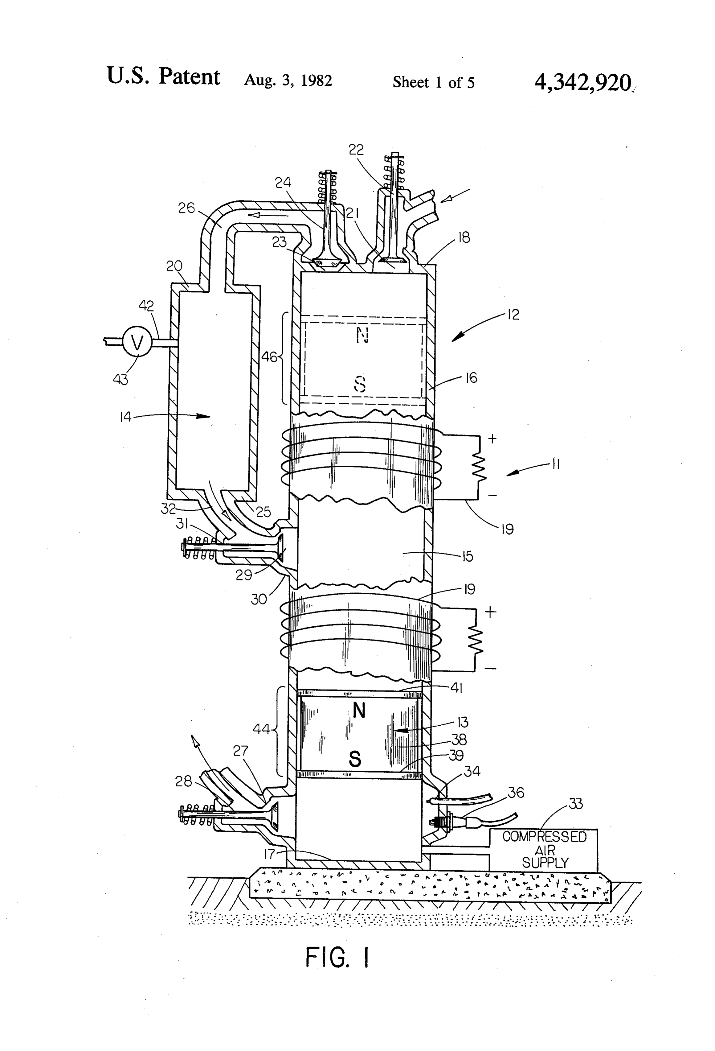
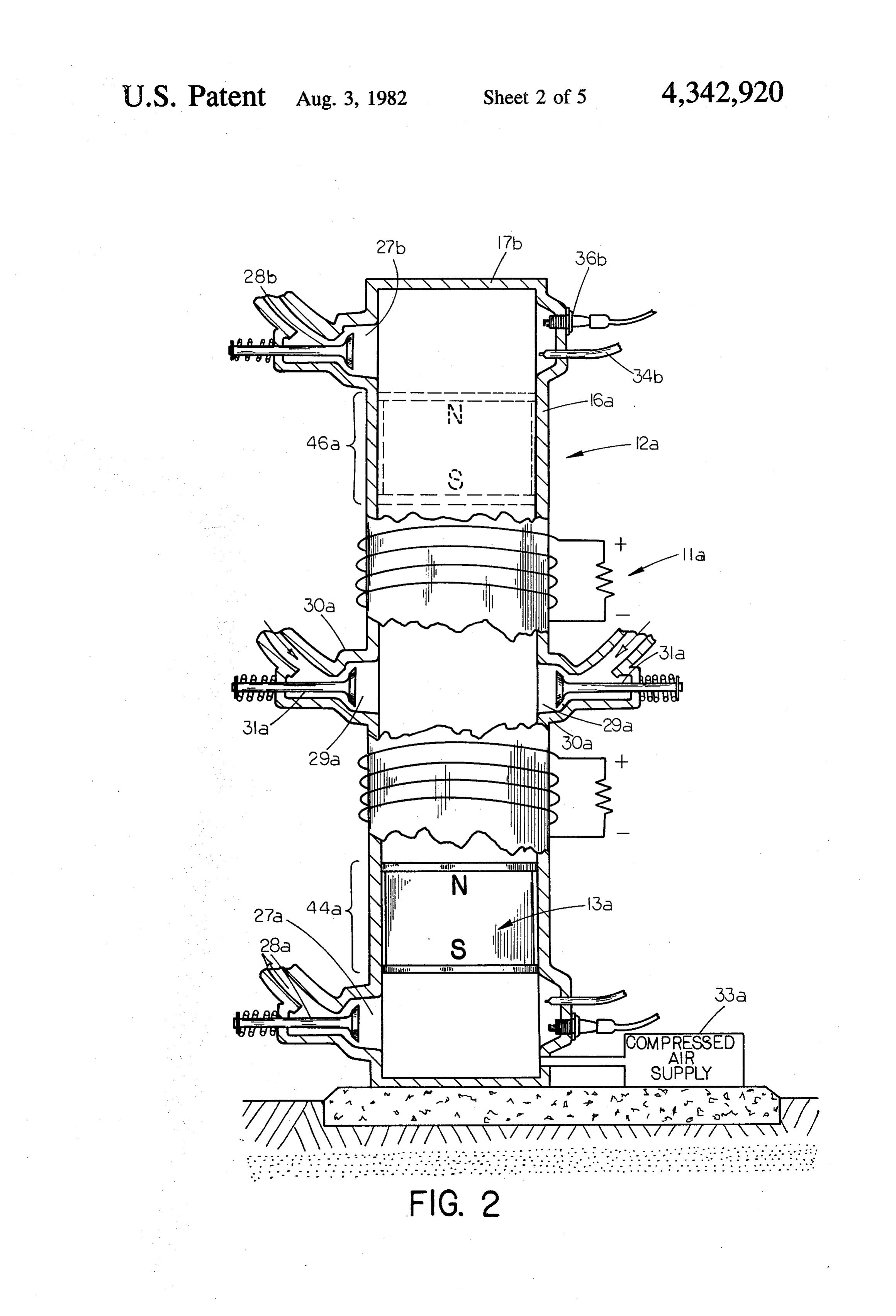
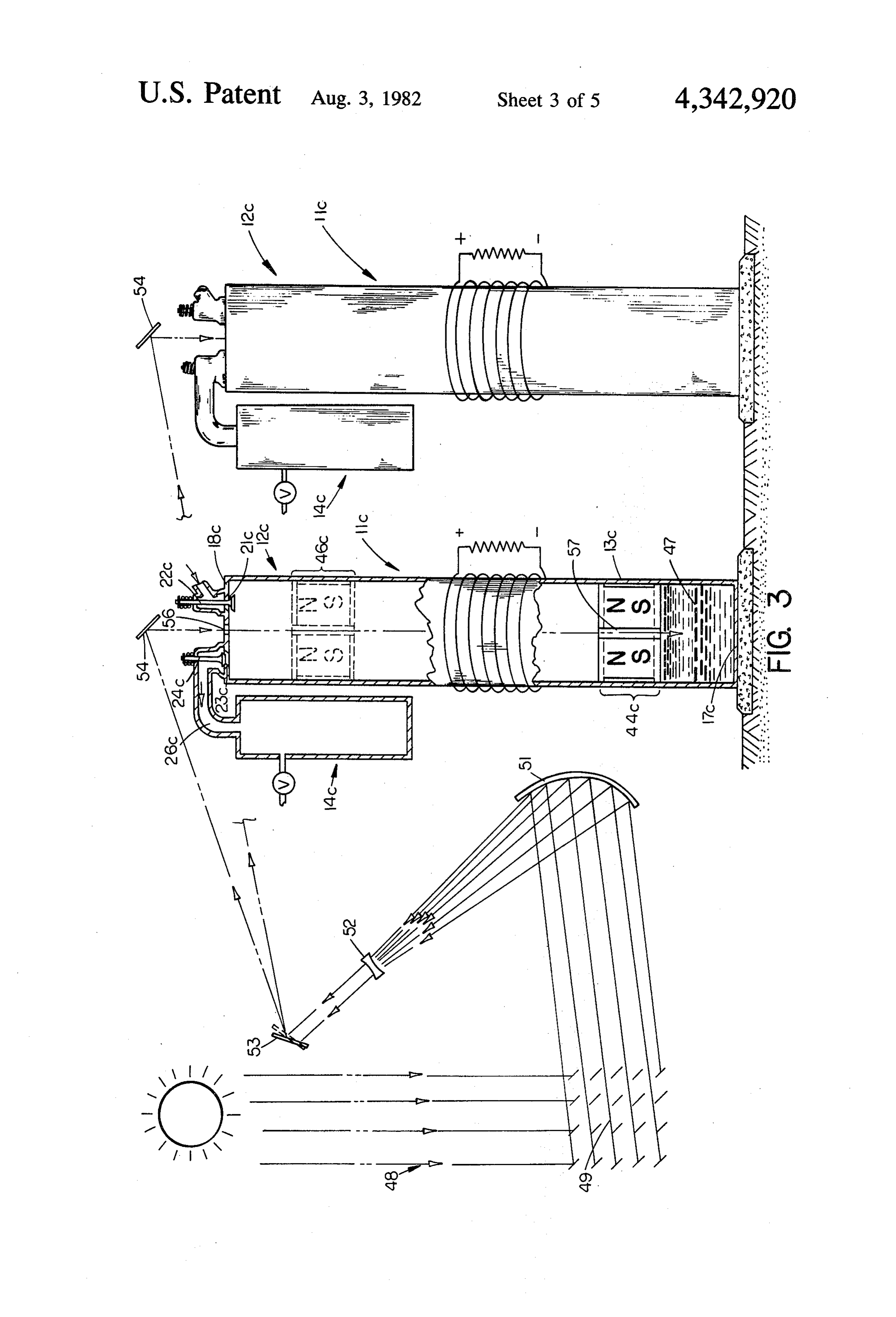
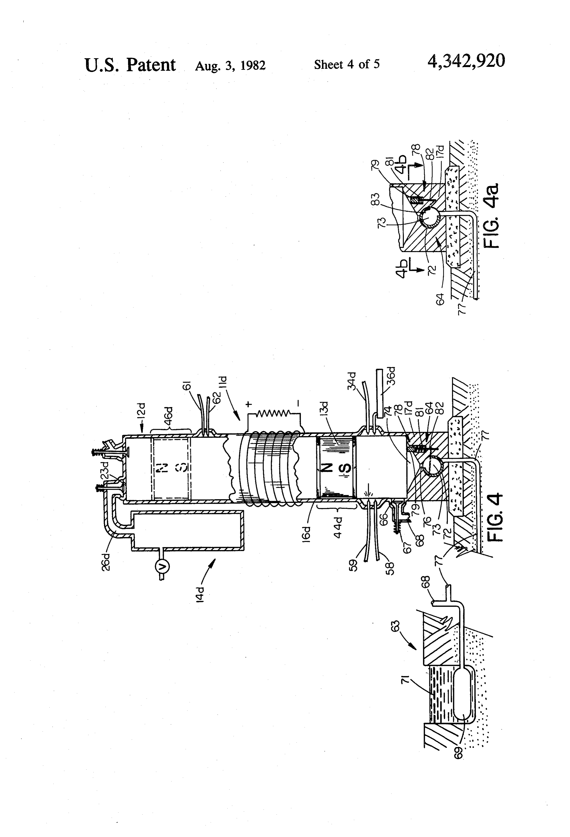
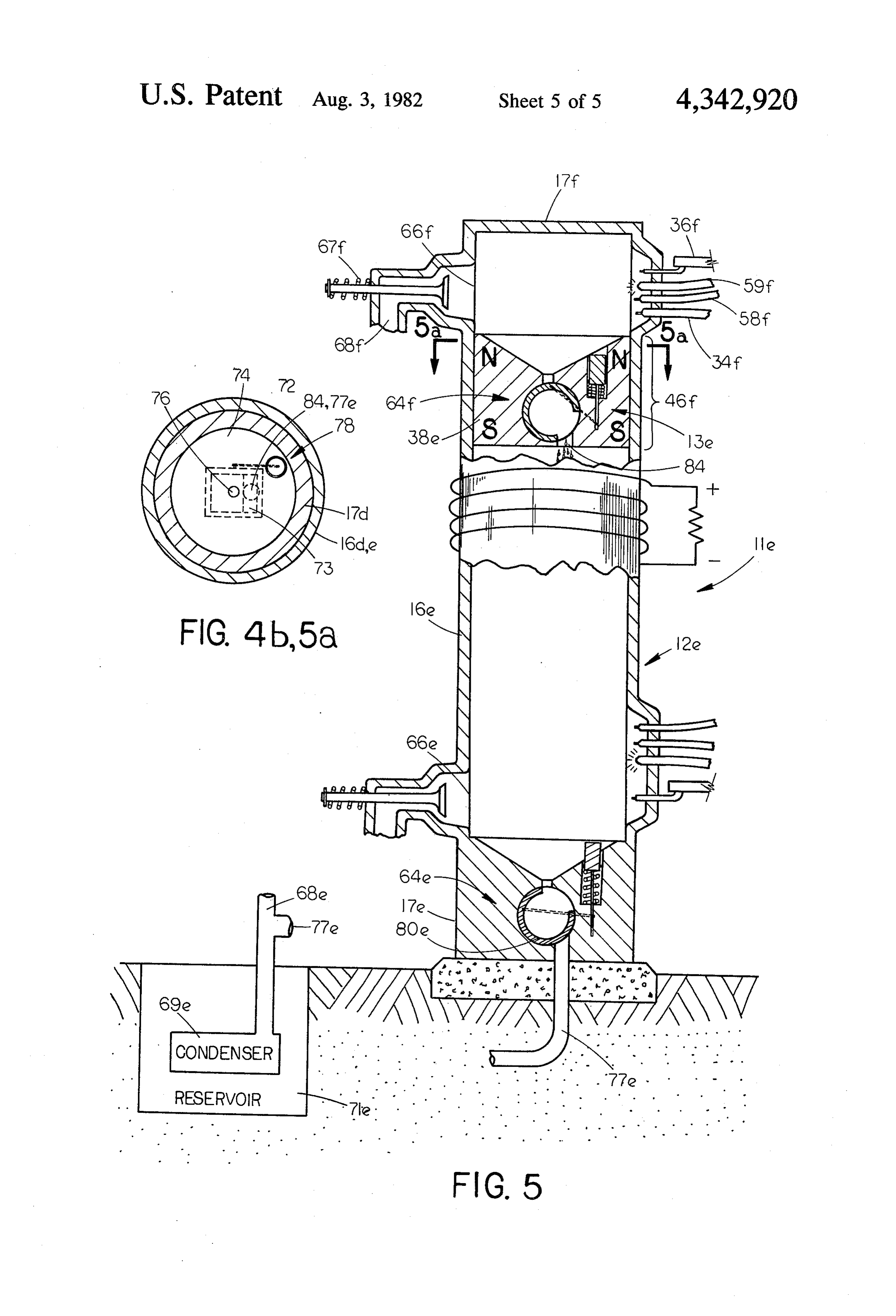
FIG. 1 is a diagrammatic fragmented, cross-sectional
Page 2drawing sheetscan →
Page 3drawing sheetscan →
Page 4drawing sheetscan →
Page 5drawing sheetscan →
Page 6drawing sheetscan →
Page 7scan →
heat energy by directing it through a transparent struc
POWER PLANT AND PROCESS UTILIZING ture in the upper end of the cylinder and a transparent GRAVITATIONAL FORCE core in the piston onto a black colored liquid in its lower end so that the liquid will vaporize.
BACKGROUND OF THE INVENTION 5 Yet other embodiments employ burning hydrogen to 1. Field of the Invention form water, first creating heat and pressure and then a This invention relates generally to power plants and vacuum beneath and then above the piston. processes for converting energy from fuel or other Thus, in addition to gravity acting alone and a second sources for expanding or contracting gases into useful 10 combustion chamber at the upper end, the other means forms of energy which incorporate enclosed expansion for returning the piston to its starting position are air chambers, wherein gases expand or contract anterior to compressed above the piston and the condensation of a piston slidably operable within a cylinder and more vapor when concentrated solar energy is used to expand particularly to such processes and devices which do not a liquid beneath the piston or hydrogen is burned in the require mechanical means of transferring the energy presence of atomized water.
from the piston or a structure such as a flywheel to 15 An object of the present invention is to provide a serve as a reservoir of potential and kinetic energy. process for converting energy into useful forms without 2. Description of the Prior Art employing expensive, heavy and dangerous moving Conventional internal (gas) or external (steam) com parts, such as connecting rods, cranks, crankshafts, and bustion engines have long been employed to convert 20 flywheels.
fuel energy into various forms of stored energy or to Another object of the invention is the economic con operate moving apparatus. Such devices have tradition version of fuel or solar energy into electrical energy ally employed mechanical means of transferring the energy such as connecting rods, cranks, and crank regardless of the size of the device. Still another object of the invention is to circumvent shafts. Also, they generally require a flywheel of greater or lesser affect depending upon various factors, 25 the limits imposed by mass, intertia, momentum, wear such as the number of pistons, the massiveness of engine maintenance, and manufacturability of the parts. parts, and the requirements for smooth and constant A further object of the invention is to convert fuel or flow of energy. In addition, other conventional parts solar energy into compressed air for use as a supplemen are required, such as piston pin bearings, crosshead tal source of stored energy.
bearings, crank pin bearings, and journal end bearings, 30 Still further objects are to eliminate costly and mas all needing lubricating means. The momentum acquired sive parts, reduce the consumption of fuel, and reduce by the piston must be cancelled by the crank at the end pollution.
of every stroke. Yet another object is to provide a simpler device, less If the device employs internal combustion, either a expensive to build and thus requiring less fuel than crankcase or turbine is required. If it uses external com 35 would be otherwise required.
bustion, a burner, boiler, turbine and smokestacks are Yet a further object of the invention is to utilize space needed. (All of the latter are dispensed with in the pres occupid by the secondary parts of a conventional en ent invention.) gine for the principle parts of the electrical energy gen To meet demands for strength and stress, such auxil erating parts of the present invention. iary parts require additional materials, all of which Other objects, advantages and novel features of the reduce the ratio of energy available to perform work to present invention will become apparent from the fol the fuel consumed. Correspondingly, downtime for lowing detailed description of the invention when con maintenance and repairs is reduced. Furthermore, appli sidered in conjunction with the accompanying draw cations such as power plants, which are designed to produce great quantities of energy, have size limitations 45 1ngs.
governed by the strength and stress-withstanding prop BRIEF DESCRIPTION OF THE DRAWINGS erties of available materials.
FIG. 1 is a diagrammatic fragmented, cross-sectional
SUMMARY OF THE INVENTION side view of the preferred embodiment wherein a drive A piston containing a magnet is repeatedly impelled 50 assembly comprising an air reservoir is shown; upwards within an enclosed cylinder having a load-con sideFIG. view 2 is a diagrammatic fragmented, cross-sectional of an alternate embodiment wherein fuel in nected electrical conductor coil surrounding its center portion. Alternating electrical current is induced in the jecting, igniting and exhaust structures are shown at conductor coil in response to the upwards and down both ends of the cylinder;
wards movements of the magnet. The preferred em 55 FIG. 3 is a diagrammatic fragmented, cross-sectional side view of an alternate embodiment wherein a struc bodiment provides for the injection and ignition of fuel near the lower end of the cylinder and the storage of ture for vaporizing and expanding a liquid by concen compressed air produced by the upward motion of the trated solar energy is shown; piston in a reservoir to be then used to assist in exhaust FIG. 4 is a diagrammatic fragmented, cross-sectional ing contaminated gases, to provide more complete com side view of an alternate embodiment wherein structure bustion, and to provide an additional source of energy for burning hydrogen below the piston assembly and a in the form of compressed air. drain release valve for surplus water is shown; An alternate embodiment does not include a com FIG. 4a shows the drain release valve of FIG. 4 in its pressed air reservoir, but provides for the injection and release attitude;
ignition of fuel alternately at both ends of the cylinder. 65 FIG. 4b is a sectional view of the embodiment of Another alternate embodiment includes a compressed FIG. 4 taken through line 4b-4b of FIG. 4; air reservoir to provide an additional source of energy FIG. 5 is a diagrammatic fragmented, cross-sectional and utilizes concentrated solar energy as a source of side view of an alternate embodiment wherein structure 8 for burning hydrogen below and above the piston as In the present invention, the momentum needed to sembly and two drain release valves are shown; and achieve the exhaust, intake, and compression cycles in a FIG. 5a is a sectional view of the embodiment of conventional fashion, resides entirely within the piston FIG. 5 taken through lines 5a-5a of FIG. 5. and that which was lost to turn a crank is now available DESCRIPTION OF THE PREFERRED to compress the charge. Furthermore, there is practi EMBODIMENTS cally no limit to the speed of the piston or distance of its travel. Increasing its velocity results in an increased
Preferred Embodiment compression ratio, a correspondingly smaller combus tion chamber. The invention, having no crank, makes
Referring now to the drawings, wherein like refer 10 varying ence numerals designate identical or corresponding also permits the compression ratio an easy matter, which parts throughout the five embodiments, and more par by employment of various types of fuels. Also increasing ticularly to FIG. 1, the preferred embodiment, the load placed upon the fuel delivered to or decreasing the power plant is depicted generally as 11 includes a cylin may be increased without the device, the speed of the piston der assembly 12, a piston assembly 13, and an air reser 15 by increasing the pressure limit. It may be slowed down and quantity of air it is pump voir 14. The cylinder assembly 12 is comprised of a ing or the amount of electricity it is producing. With a cylinder wall 16, a lower end wall 17 attached to the vertical cylinder and unconnected piston, losses due to cylinder wall 16 at or near the ground, an upper end friction should be minimal.
wall 18 attached to the upper end of the cylinder wall Air reservoir 14 has a take-off tube 42 with check 16, and a load-connected electrical conductor coil 19 20 valve 43 mounted therein. As will be noted hereinafter, surrounding a center portion 15 of the cylinder. The air reservoir 14 may be utilized as a supplementary center portion 15 of the cylinder 16 must be of a non source of stored energy by tapping compressed air magnetically-responsive material of either metal or through tube 42. In addition, storing and releasing en ceramic. By properly supporting the upper half of the ergy in this manner further provides for fluctuations in cylinder, the walls of the central part of the cylinder 15 25 load.
between the ends may be relatively thin, thus permitting The process of converting energy with the power the coil to be in close proximity to the magnetic piston, plant
As compared to the center portion 15, most other parts phase.11Prior includes a starting phase and a repeating cycle of the cylinder assembly 12 especially the end walls, are assembly 13 isto heldinitiating the starting phase, the piston at rest at starting position 44 by a subject to higher demands for structural strength, heat 30 small column of compressed air maintained by com resistance, and pressure resistance. Materials with ap pressed air supply 33. Compressed air supply 33 then propriate properties are well known and are required lifts the piston assembly 13 to an apex position 46 near for the device to function properly.
The upper end wall 18 of the cylinder assembly 12 cept outlet port 23 are in closed position soall upper end wall 18. During this operation ports ex as to permit has an inlet port 21 with a spring-biased valve 22 35 the column of air above piston assembly 13 to pass mounted therein and an outlet port 23 with a spring through tube 26 into air reservoir 14, creating a supply biased valve 24 mounted therein which is connected by of compressed air therein. When piston assembly 13 a tube 26 to first end 20 of air reservoir 14. Adjacent the reaches apex position 46, compressed air supply 33 is lower end wall 17, located in cylinder wall 16 is an turned off and valve 28 in outlet port 27 is allowed to exhaust outlet port 27 for exhausting contaminated 40 gases with a mechanically operated spring-biased ex open so as not to impede the free fall of piston assembly 13. The free falling piston assembly 13 will pull open haust valve 28 mounted in it. A second inlet port 29 valve 22, permitting fresh air to enter through inlet port located in protrusion 30 of cylinder wall 16 intermediate 21 and allow valve 24 to close, sealing off the supply of the ends of the cylinder assembly 12, having valve 31 compressed air now in air reservoir 14. When piston mounted in it, is connected by tube 32 to second end 25 45 assembly 13 has reached a point where, after exhaust of air reservoir 14. valve 28 is closed the air being compressed beneath it Completing the cylinder assembly 12, compressed air will not stop it from reaching starting position 44, ex supply 33 (which could be a compressed air reservoir or haust valve 28 is then closed. The mass of the piston and a conventional starter air pump), a conventional fuel the time of the closing of valve 28 will determine the injector 34, and a conventional fuel ignition structure 36 50 compression ratio and therefore the size of the combus are connected to cylinder assembly 12 through a protru tion chamber.
sion in the cylinder wall 6 adjacent the end wall 17. In Prior to piston assembly 13 returning to starting posi addition, electronic timing devices (not shown) and tion 44, fuel is injected by fuel injector 34, and, as piston hydraulic or solenoid switches (not shown) are pro assembly 13 reaches starting position 44, the fuel is vided for controlling spring-biased valves (22, 24, 28, 55 ignited, forcing piston assembly 13 again to apex posi and 31), fuel injector 34, and ignition structure 36, so as tion 46. During this ascent of piston assembly 13 the to synchronize their functioning in accordance with the spring-biased valves 22 and 24 will direct the column of process for converting energy as hereinafter described. air above piston assembly 13 to enter through tube 26 The piston assembly 13 is slidably operable within the into air reservoir 14, further compressing the air therein cylinder assembly 12 and includes an intermediate bar so long as valve 31 continues to be held in a closed magnet in the form of a magnetic disc 38 which has a position. However, as piston assembly 13 ascends past lower ceramic plate 39 and an upper ceramic plate 41 inlet port 29, spring-biased valve 31 is allowed to open secured to its lower and upper ends, respectively, to and admit a charge of compressed air below the piston serve as piston rings. The polar axis of the bar magnet which assists in pushing the piston upward and expel 38 is oriented so that it coincides with the longitudinal 65 ling the contaminated gases beneath piston assembly 13 axis of the cylinder assembly 12. The upper and lower downward through exhaust port 27 and supplies a fresh plates 39 and 41, may be of other non-magnetically charge of compressed air beneath the piston assembly responsive material such as copper or aluminum. 13. After a sufficient charge of compressed air is passed 9 through inlet port 29, spring-biased valve 31 is again held open so as to permit the free fall of piston assembly held closed, causing the column of air remaining above 13a, piston assembly 13 to be forced into air reservoir 14 as As the piston assembly 13a descends past inlet port the momentum of the piston assembly 13 continues to 29a, inlet valve 31a is open, and outlet valves 28a and carry it up to the apex position 46. The first cycle of the 28b close, causing the descending piston assembly 13a repeating cycle has now been completed and the second to compress the air remaining beneath it while drawing cycle is initiated as was the first by piston assembly 13 air in above it through intake port 29a, Then duplicating beginning its second free fall towards cylinder assembly the process of power plant 11, fuel is injected prior to end wall 17. piston assembly 13a reaching starting position 44a and The timing of each step of the process is controlled 10 ignited as it reaches starting position 44a, Valve 31a by electronic timing devices through conventional then closes and exhaust valve 28b opens permitting the switches operated by solenoids or by hydraulic or me exhaust to escape. As piston assembly 13a ascends past chanical controls where necessary. Electronic timing inlet port 29a valve 31a opens and valve 28b closes, devices which have provisions for adjustments to allow 15 drawing in clean air beneath the piston assembly 13a for variations in fuel, atmospheric pressure, tempera and compressing air above it as the momentum of the ture, etc., are well known; and, under a given set of pistonPrior carries it to its apex position.
to piston assembly 13a reaching apex position parameters, gravity being constant, once an appropriate timing sequence is determined, the energy converting 46a, fuel is admitted by fuel injector 34b. As piston deivce 11 will continue the repeating cycle. By employ 20 assembly 13a reaches apex position 46a, the highly com pressed air and fuel mixture above it is ignited by igni ing a plurality of valves, directional intake and outlet tion ports, as well as baffles (not shown); adequate breathing structure 36b. Intake valve 31a is then closed and and forcing of contaminated gases downwards without ing cyclevalve exhaust 28a is opened. At this instance the repeat of power plant 11a is initiated and all of the mixing with intake air, may be insured.
Energy will be converted into electrical energy as the valves, fuelbyinjectors, and ignition structures, being magnetic forces of the magnetic disc 38 pass by the 25 controlled electronic timing devices (not shown) operate in the same sequence as described above follow electrical conductor coil 19, thereby inducing an elec ing the first descent of piston assembly 13a from apex tric current. Means for converting the alternating cur rent thus produced into suitable frequencies and volt position 46a. In the case of energy converting device ages for transmission over long distances are well 30 assembly 12a andrequirements 11a, the material with respect to cylinder known and not shown herein. Also, stored energy is those of energy converting device13a11 are piston assembly and identical to electronic available in the form of compressed air by opening timing devices will maintain sequential control, after valve 43 mounted in take-off tube 42. necessary adjustments, of the various elements includ First Alternate Embodiment ing conventional valve-switching gear. Fuel energy will 35 be converted into electrical current by induction in like
Referring now to FIG. 2, an alternate embodiment of lane.
the power plant is depicted generally as 11a and in cludes a cylinder assembly 12a and a piston assembly airAsis inadmittedconventional internal combustion engines, fresh through inlet port 29a whenever atmo 13a. This embodiment differs from the preferred em spheric pressure (plus or minus 14 PSA) exceeds the bodiment in that it does not include an air reservoir with pressure behind the piston as it moves up or down; its attendant parts nor inlet and outlet ports with valves however, superchargers may be utilized if desired. for pumping fresh air in its upper end wall, but has instead, adjacent its upper end wall 17b, connected to Second Alternate Embodiment cylinder assembly 12a through cylinder wall 16a, the Referring now to FIG. 3, a second alternate embodi same elements power plant 11 has adjacent its lower 45 ment of the power plant is depicted generally as 11c and end, with the exception of a compressed air supply also includes a cylinder assembly 12c and a piston as structure 33. These elements include exhaust outlet port sembly 13c, as well as an air reservoir 14c. In this em 27b with spring-biased exhaust valve 28b mounted in it, bodiment, at least two complexes of cylinder assembly fuel injector 34b, and fuel ignition structure 36b, all 12c, piston assembly 13c, and air reservoir 14c are syn located in cylinder wall 16a adjacent to upper end wall SO chronized so as to produce a more constant supply of 17b, Intermediate the ends of cylinder assembly 12a are converted energy and to maximize the use of sunlight. one or more inlet ports 29a located in protrusions 30a in Although an air reservoir 14c is shown for each power cylinder wall 16a and having valves 31a mounted in plant complex, a single air reservoir could serve several them. In all other respects the power plant 11a has parts such complexes. This embodiment differs from the pre parallel to those of power plant 11 and said parts are 55 ferred embodiment in that air reservoir 14c is not con designated by corresponding numerals with the letter nected to an inlet port in cylinder wall 16c intermediate 'a' appended thereto. the ends of the cylinder assembly 12c and in that cylin The process of converting energy with the power der assembly 12c has (in place of a valved outlet port, a plant 11a includes a starting phase identical to that of compressed air supply means, a fuel injector, and a fuel the starting phase of power plant 11, piston assembly 60 ignition structure) a black colored liquid 47 contained 13a being lifted by compressed air from 33a to apex beneath starting position 44c and adjacent its lower end position 46a near upper end wall 17b and exhaust valve wall 17c a volume of inert gas (now shown) above liquid 28b being allowed to open so as to permit the column of 47, and a concentrated solar energy assembly 48. air above piston assembly 13a to pass through exhaust Concentrated solar energy assembly 48 for vaporiz outlet port 27b. As in the preferred embodiment, after 65 ing the black colored liquid 47 includes conventional piston assembly 13a reaches apex position 46a, com heliostat reflectors 49, parabolic concentrator-reflector pressed air supply 33a is turned off and exhaust valve 51, concave lens 52, movable reflector 53, stationary 28a is allowed to open and valves 28b and 31a are also reflector 54, solid transparent portion 56 of upper end 10 wall 18c, and solid transparent core portion 57 of the lection of beams to become a concentrated parallel piston assembly 13c. In all other respects power plant beam and is located so as to direct this beam onto a 11c has parts parallel to those of power plant 11 and said movable mirror 53. Mirror 53 is controlled by solenoid parts are designated by corresponding numerals with - or hydraulic means to alternately direct the concen the letter 'c' appended thereto. trated solar energy to the several stationary mirrors 54 As in the Preferred Embodiment, the process of con where the beam is alternately reflected through trans verting energy with power plant 11c includes a starting parent portion 56 of upper end wall 18c and transparent phase and a repeating cycle phase. Prior to initiating the core portion 57 of piston assembly 13c onto the black starting phase, the piston assembly 13c is held at rest at colored liquid 47 in each cylinder assembly 12c. starting position 44c by resting upon the volume of inert 10 As in the case of power plant 11 and 11a, the material gas above the black colored liquid 47. The inert gas requirements with respect to cylinder assembly 12c and serves to produce the effect of a bounce chamber for piston assembly 13c are identical except for the trans piston assembly 13c. In this embodiment, the starting parent portion 56 in upper end wall 18c and the trans phase is initiated by the vaporization of liquid 47 when parent core 57 in piston assembly 13c. A suitable agent concentrated solar energy is directed upon it. The black 15 for coloring the liquid 47 black is graphite containing colored liquid 47 is thereby vaporized forming an ex some oil lubricant. Electronic timing devices will main panding gas which lifts the piston assembly 13c to apex tain sequential control of the movable mirror 53. After position 46c near upper end wall 18c. During this opera necessary adjustments of the various elements including tion, the column of air above piston assembly 13c passes conventional valve switching gear, concentrated solar through outlet port 23c and tube 26c into air reservoir 20 energy will be converted into electrical current by in 14c creating a supply of compressed air therein. When duction in like manner. Compressed air stored in air the vapor expanding beneath piston assembly 13c is reservoir 14c provides an additional source of con sufficient to left it to apex position 46c, movable reflec verted energy.
tor 53 of solar energy means 48 directs concentrated The inventor believes that a more efficient way to solar energy to another stationary reflector 54 of an 25 utilize solar energy is to convert it first to chemical other complex, allowing piston assembly 13c to free fall energy so as to dissociate the elements of a liquid into its as black colored liquid 47 cools and condenses. The free elements hydrogen and oxygen with the aid of a catay falling piston assembly 13c will pull open valve 22c list, such as a rhodium compound, and later liberate this permitting fresh air to enter through inlet port 21c and stored energy by recombining and releasing their heat allow valve 24c to close, sealing off the supply of com 30 inside an engine. For an explanation of this method of pressed air now in air reservoir 14c. Prior to piston producing hydrogen and oxygen see Popular Science, assembly 13c returning to starting position 44c, and as Science Newsfront, p. 61 (May 1980). The stored chem the vaporized black colored liquid 47 has begun to ical energy far exceeds the latent heat required to condense and accumulate adjacent to lower end will achieve the phase change which converts water into 17c, concentrated solar energy means 48 is again di 35 vapor. There might be enough heat given off in the rected to the original stationary reflector 54 in order process of forming water that the pressure of the vapor that the black colored liquid reaccumulating in the bot immediately after its formation may be the same as that tom of cylinder assembly 12c is maintained at whatever of the hydrogen and oxygen gas immediately before its temperature above its boiling point which is desired burning.
with respect to operational requirements. 40
When piston assembly 13c has reached its starting Third Alternative Embodiment position 44c, the first repeating phase is initiated by the Referring now to FIGS. 4 and 4a, an additional alter revaporization of the black colored liquid 47. In this nate embodiment of the power plant is depicted gener embodiment of the energy converting device the only ally as 11d and also includes a cylinder assembly 12d difference between the starting phase and the repeating 45 and a piston assembly 13d, as well as an air reservoir phases is that the temperature of the black colored liq 14d. This embodiment is similar to the embodiment uid 47 is ambient only in the starting phase and is higher employing concentrated solar energy in that air reser during any repeating phase. Thus, the velocity of the voir 14d is not connected to an inlet port in cylinder ascending piston may be varied by controlling the oper wall 16d. is different than the concentrated solar energy ating temperature of the condensed black colored liquid 50 embodiment in that it does not employ concentrated 47. There must be enough inert gas above the water in solar energy nor any of the complementary elements the cylinder to provide a bounce chamber at the bottom and structures, and is similar to the preferred embodi of the cylinder which will deter the falling piston from ment in that it employs fuel injector 34d and ignition ever physically striking the liquid. Were the piston to structure 36d for the introduction and ignition of a fuel; suddenly free fall against the liquid upon the setting of 55 in this embodiment that fuel is hydrogen gas. the sun or sudden moving in of cloud cover, the shock This hydrogen burning embodiment also includes would undoubtedly do great damage to the cylinder oxygen injector 58, water injecting atomizer 59, second unless other cushioning steps were taken. w hydrogen injector 61, second oxygen injector 62, water It is believed that the method for producing and di vapor condensing assembly 63, and automatic drain recting a beam of concentrated solar energy may not be relief valve assembly 64.
generally known by those skilled in the pertinent art The water vapor condensing assembly 63 includes and, therefore, the following explanation is included vapor outlet port 66 with a spring-biased valve 67 herein. Sunlight is reflected by heliostat 49, which is mounted therein connecting tube 68 to a separate con comprised of a large array of steered mirrors. As the sun densor 69 which contains a near perfect vacuum and is moves across the sky, the heliostat 49 directs the beams 65 enveloped by chilled water 71. to a parabolic concentrator-reflector 51 which is fixedly Drain release valve assembly 64 includes cylinder 72 mounted and which directs the collection of beams which revolves within a recess within thickened lower through a concave lens 52. The lens 52 causes the col end wall 17d. Said cylinder 72 has a pocket 73 to receive 11 condensed water vapor collected by concave depres tively pure mixture of hydrogen and oxygen gas imme sion 74 of end wall 17d and throat 76 of end wall 17d diately above the water and below the piston. The and eject said condensed water vapor through outlet downward motion of the piston is eventually stopped tube 77. Outlet tube 77 may be connected to separate by the increasing gas pressure, resulting is a bounce condensor 69 either directly or through connecting chamber effect at the bottom of the cylinder. When tube 68. Tube 77, being connected to condenser 69 piston 13d reaches starting position 44d, if the hydrogen which contains a vacuum, will also contain a vacuum; beneath it does not pre-ignite, ignition structure 36d said vacuum will assist gravity in removing water from ignites the mixture, turning the bounce chamber into a pocket 73. Drain release valve assembly 64 also includes combustion chamber and initiating the first repeating pressure control structure 78 which has activating pis 10 phase. The heat of combustion of hydrogen and oxygen ton 79, compression spring 81, shaft 82, and connecting then vaporizes the water droplets still falling and col rod 83. In operation, compression spring 81 holds acti lecting on the cylinder walls and in concave depression vating piston 79 in raised position, as best can be seen in 74. The resulting tremendous quantity of heat vaporizes FIG. 4, until the pressure within cylinder assembly 12d additional water to create more steam which again and beneath piston assembly 13d rises to a pre-set level 15 drives the piston to apex position 46d. Water injecting sufficient to force shaft 82 downwards to the position atomizer 59 provides this additional water immediately which can best be seen in FIG. 4a. Connecting rod 83 before combustion occurs. Cooling within the cylinder, being pivoted between a fixed position on cylinder 72 between combustions, reduces the need for removing and the lower end of shaft 82 will then cause cylinder 72 to rotate from its collecting position as can be seen in 20 excess heat which can now be tapped at the condenser. If a long stem cylinder is used, separate condensor
FIG. 4, to its dispensing position as can be seen in FIG. assembly 63 may not be required. A fresh, cold, high
In all other respects, power plant 11dhas parts paral pressure charge of hydrogen and oxygen could be ad lel to those of power plant 11 and said parts are desig injectors 61various mitted at locations below the pistons, as by and 62, when the piston is still at apex posi nated by corresponding numerals with the letter "d' 25 tion 46d rather than after it has returned downward to appended thereto.
The process of converting energy with power plant the cylinder. If thebetween a position midway charge the upper and lower ends of were admitted immediately 11d is most analogous to that of the concentrated solar below the piston while the piston is at apex position 46d, energy embodiment herein next above described. Its the incoming mixture would cool and condense the starting phase is initiated by the injection of two parts 30 water vapor residing there and draw hydrogen and one part oxygen beneath the piston as water vapor from below upwards. The the remaining resulting con sembly to lift it to a starting position 44d. Water is then densed water droplets falling down the cylinder walls injected through the atomizer or nozzle structure 59 or precipitating as rain would further condense the simultaneously with the ignition of the gases beneath remaining water vapor below the piston. Increased the piston assembly. In this embodiment a laser or other 35 pressure, type of igniter must be used because a spark plug will caused by the incoming mixture would also not function in the moist environment. This results in tend to condense the vapor. super-heated steam adequate to force piston assembly Controls of conventional nature well known in the 13d to apex position 46d forcing the column of air above art are employed to balance the removal of water vapor piston assembly 13d through outlet port 23d and tube through port 66 into separate condensor 69 and the 26d into air reservoir 14d. As the steam beneath piston removal of condensed water by drain relief valve as assembly 13d begins to condense, a vacuum is created sembly 64 with the quantity of water entering the cylin which assists the return of piston assembly 13d to start der assembly 13d through water atomizer 59 and by ing position 44d. reason of the combustion of the injected hydrogen and After piston 13d reaches apex position 46d, valve 67 45 oxygen. It should be appreciated also the either the opens port 66 to permit remaining water or water vapor water vapor port 66 or the drain relief valve assembly to escape from the bottom of the cylinder to the cooled 64 alone could provide the function of removing surplus separate condensor 69, which always contains a near Water.
perfect vacuum. Thus, a vacuum beneath the piston is Fourth Alternate Embodiment provided for a longer period of time, thereby assisting 50 gravity in returning the piston to starting position 44d. Yet another embodiment of the power plant is de When piston 13d has reached a position about halfway picted in FIGS. 5 and 5a, which like the next preceding down the cylinder, valve 67 is closed and hydrogen and embodiment relies upon the ignition of a mixture of oxygen injectors 34d and 58 in the lower end of the hydrogen and oxygen in the presence of atomized wa cylinder again admit a fresh charge of two parts hydro 55 ter. This embodiment which is indicated generally as gen and one part oxygen, respectively. When the new 11e, differs from the previous embodiment in that it charge is released from pressurized containers into the does not include an air reservoir with its attendant parts, partial vacuum, it expands, cools, and further increases nor in inlet port with valve for pumping fresh air the pressure, thus causing any remaining water vapor through its upper end wall, but has, instead, adjacent its residing in the cylinder to condense on the cylinder upper end wall 17f, connected to cylinder assembly 12e walls. This precipitation provides an even greater vac through cylinder wall 16e, the same elements, power uum, thereby allowing for the addition of more of the plant 11d has adjacent its lower end. These elements gaseous components of water. include hydrogen injector 34f fuel ignition structure As piston 13d, on its way down, starts to compress 36f oxygen injector 58f water vapor atomizer 59f the new charge, its velocity is reduced by the increasing 65 water vapor port 66f spring-biased valve 67f, and con gas pressure beneath it. The water droplets continue to necting tube 68f for the transmission of water vapor to fall at the same, or increased, rate of speed and collect in separate condensor 69. Power plant 11e also has a drain concave depression 74 of endwall 17d, leaving a rela relief valve assembly 64e which has the same elements 12 as valve assembly 64, said elements depicted by append valve mounted in a first inlet port in said upper end ing the letter "e" to the corresponding numerals. in order to admit a charge of fresh air and opening The piston assembly 13e has within a magnetic disc a spring-biased mechanically operated exhaust 38e, a drain relief valve assembly 64f which includes all valve mounted in a second outlet port in said lower of the elements of the drain release valve assembly 64e, end;
which in turn is identical to drain relief valve assembly closing the valve in said second outlet port at the 64 of power plant 11d, located in the thickened lower bottom of the cylinder when the piston means has end 17e of cylinder assembly 12e, with the exception of fallen far enough to enable it to compress as much drain pathway 77e. In lieu of pathway 77e drain release fresh air beneath it to allow it to reach said starting assembly 64f has a pathway 84 which serves to permit 10 point;
water to flow from drain release valve assembly 64f into injecting fuel into the air in the cylinder means be cylinder assembly 12e beneath piston assembly 13e. In neath said piston means starting position prior to its all respects, drain release valve assembly 64e and 64f reaching said starting position; operate in the same manner as drain release valve as igniting the fuel and air mixture at approximately the sembly 64, except that pathway 84 directs the exiting 15 instant when said piston means has reached said water into the cylinder beneath piston 13e. starting position thereby forcing said piston means In all other respects, power plant 11e has parts paral towards the upper end, again opening said first lel to those of power plant 11d and said parts are desig outlet port for transferring the column of air above nated by corresponding numerals with the letter "e' and ahead of said piston means into said reservoir; appended thereto. 20
The process of converting energy with the power opening a valve mounted in a second inlet port, inter plant 11e includes a starting phase identical to that of mediate the lower and upper ends of said cylinder the starting phase of power plant 11d, with the excep means, and connected by pipe to a lower end of tion that all of the air above piston assembly 13e has said reservoir means, as the piston means passes been replaced by steam which, upon condensing, draws 25 upwardly by, in order that compressed air in the the piston assembly upward. The piston assembly 13e is reservoir will enter the cylinder means behind the also lifted by super-heated steam from below, to apex piston between the piston means and the lower end position 46f near upper end wall 17f of said cylinder means and expel the contaminated Prior to piston assembly 13e reaching apex position gases through the second outlet port; and 46f hydrogen injector 34f and oxygen injector 58f 30 closing said second inlet port when the piston means admit hydrogen and oxygen in the ratio of two parts to has again reached a point near the upper end of the one part, respectively, into cylinder assembly 12e above cylinder means and is in position to again free-fall apex position 46f, and as cylinder assembly 13e reaches for the next repetition of the cycle. apex position 46f, additional water is admitted above 2. The process as defined in claim 1 wherein said steps apex position 46f by water atomizer 59f and simulta 35 of holding the piston means at a starting position and neously the ignition structure 36f ignites the hydrogen. lifting it to an apex position are carried out by admitting At this instance the repeating cycle of power plant 11e compressed air.
is initiated and all of the valves, injectors, and ignition 3. A device for converting fuel energy into useful structures, being controlled by electronic timing de other forms of energy, such as inducing an alternating vices (not shown), also operate in the same sequence 40 current in a coil, comprising:
and in similar manner as described above for the starting means for holding a piston means forming a magnetic phase of power plant 11d. field at a starting position near a lower end of a Obviously, numerous modifications and variations of cylinder means also having an upper end, with a the present invention are possible in light of the above load-connected electrical conductor coil means teachings. It is therefore to be understood that within 45 surrounding it intermediate the ends thereof; the scope of the appended claims, the invention may be means for lifting said piston means to an apex position practiced otherwise than as specifically described near the upper end of said cylinder means; therein.
I claim: means for permitting said piston means to initiate a 1. A process for converting gas expanding energy 50 repeating cycle by free falling within said cylinder sources into useful other forms of energy, such as induc means to said starting position; ing an alternating current in a coil, comprising the steps means for injecting fuel into the air in said cylinder of: means beneath said piston means starting position holding a piston means forming a magnetic field at a and prior to said piston means reaching said start starting position near a lower end of a cylinder 55 ing position;
means, also having an upper end, with a load-con means for igniting the fuel and air mixture at approxi nected electrical conductor coil means surrounding mately the instant when said piston means has it intermediate said ends thereof; reached said starting position thereby forcing the lifting said piston means to an apex position near an piston towards the upper cylinder end from where upper end of said cylinder means thereby opening a 60 the cycle may again be repeated; and spring-biased valve mounted in a first outlet port in means for sequentially timing the injecting and ignit said upper end in order to transfer the column of air ing of the fuel, the admitting air and fuel, and the above the piston means through a tube into a reser exhausting of air and contaminated gases including: voir means; a first outlet port in the upper end of the cylinder permitting said piston means to initiate a repeating 65 having a spring-biased valve mounted thereinfor cycle by free falling within said cylinder means transferring the column of air above the piston, thereby allowing said spring-biased valve in the as it ascends, through a tube connected to an first outlet port to close, opening a spring-biased upper end of a reservoir means;
Page 13scan →
a first inlet port in the upper end of the cylinder the step of lifting the piston means to an apex position having a spring-biased valve mounted therein for comprises vaporizing the liquid by directing a concen admitting fresh air above the piston, as it falls; trated solar beam onto it; and the step of permitting said a second outlet port in the lower end of the cylin piston means to return to the starting position com der having a spring-biased mechanically oper prises, discontinuing directing the concentrated solar ated valve mounted therein for permitting the beam, allowing the vapors to condense and form a vac piston to fall initially and expel contaminated gases without compressing air beneath it so that 8. The process as defined in claim 7 wherein a second it may be closed at a predetermined time so as to said process as defined in claim 7 is initiated by directing permit the piston to reach its starting position O the concentrated solar beam onto a second quantity of and to begin to compress air beneath it; liquid which has been holding a second piston means at a second valved inlet port, intermediate the lower a starting position in the bottom of a second cylinder and upper cylinder ends and connected by a tube means at the moment the directing of the beam on the to a lower end of the reservoir means for admit first quantity of liquid is discontinued and then redirect ting compressed air from the reservoir means 15 ing the beam onto the first quantity of liquid at the into the cylinder to expel contaminated gases moment the directing of the beam on the second quan through the second outlet port and provide a tity of liquid is discontinued.
fresh charge of air after the piston passes up 9. The process as defined in claims 7 or 8 wherein the wardly by said second inlet port; and quantities of liquid are black colored. electronic timing means for synchronizing the 20 10. The process as defined in claims 7 or 8 wherein holding, lifting, and free fall permitting of the the timing of the directing, discontinuing, and redirect piston means; the injecting and igniting of the ing the concentrated solar beam is carried out with fuel; and the opening and closing of the valves. electronic timing means and a movable flat mirror. 4. The device as defined in claim 3 wherein the means 11. A device for converting gas expanding and con for holding the piston means at a starting position, lift 25 tracting energy sources into useful other forms of en ing it to an apex position, and permitting it to free fall is ergy, such as inducing an alternating current in a coil, a controlled source of compressed air which may be comprising:
same as reservoir 14. a liquid and a gas located in the bottom of a cylinder 5. The device as defined in claim 3 or 4 wherein the means to support in a starting position near a lower reservoir means 14 has a third outlet port intermediate 30 end of the cylinder means a piston means forming a the ends thereof with a valve mounted therein for tap magnetic field, said cylinder means also having an ping the surplus compressed air therein as an additional upper end and a load-connected electrical conduc source of useful energy. tor coil surrounding it intermediate said ends 6. A process for converting gas expanding energy thereof;
sources into useful other forms of energy, such as induc 35. a transparent core in said upper cylinder end and ing an alternating current in a coil, comprising the steps another in said piston means for permitting a con of: centrated solar beam to be intermittently directed holding a piston means forming a magnetic field and on said liquid in order to vaporize said liquid for slidably operable, but otherwise unattached, within lifting the piston means to an apex position near the a substantially enclosed cylinder means at a starting upper end of said cylinder means and after con position near a lower end thereof, by compressed densing, causing said piston means to return to said gas below said piston means, said cylinder means starting position to complete a cycle; having a load-connected electrical conductor coil a spring-biased valve mounted in an outlet port in the means surrounding it intermediate its ends; upper end of the cylinder means for allowing the lifting said piston means to an apex position near the 45 column of air above the piston means to be forced upper end of said cylinder means by substantially through a connecting tube;
altering the difference in gas pressure below said a compressed air reservoir to receive the air from the piston means in relation to the gas pressure there connecting tube and a spring-biased valve mounted above, thereby opening a spring-biased valve in an inlet port in the upper end of the cylinder mounted in an outlet port in the upper end of said 50 means to allow the piston means to pull a fresh cylinder means in order to transfer the column of column of air in above it as it falls to its starting air above the piston means through a tube into a position;
reservoir means; concentrated solar beam directing means; and permitting said piston means to return to said starting means for sequentially timing the directing and dis position for completion of the cycle, thereby allow 55 continuing directing of the concentrated solar ing the spring-biased valve in the outlet port to beam on the liquid.
close and opening a spring-biased valve in an inlet 12. The device as defined in claim 11 wherein a sec port in the upper end of said cylinder means in ond said device as defined in claim 11 is operated by order to admit a charge of fresh air; and intermittently directing the concentrated solar beam on stopping the downward movement of said piston the liquid in the bottom of the second device so that the means at said starting position by compressed gas two cycle phases of the two devices are one-half cycle below said piston means, thereby completing a out of step with each other.
cycle which can be repeated by starting at the step 13. The devices as defined in claims 11 or 12 wherein in paragraph three above. the liquid is black colored.
7. The process as defined in claim 6 wherein the step 65 14. A process for converting gas expanding and con of holding a piston means at a starting position is carried tracting energy sources into useful other forms of en out by the compressive support of a liquid and a gas in ergy, such as inducing an alternating current in a coil, a bounce chamber at the bottom of the cylinder means, comprising the steps of:
Page 14scan →
holding a piston means forming a magnetic field at a separate valve means for introducing charges of hy starting position near a lower end of a cylinder drogen and oxygen in ratio of two parts to one, means with the compressive support of water, said respectively, below said starting position; cylinder means also having an upper end, with a means for igniting the hydrogen-oxygen mixture lo load-connected electrical conductor coil means cated beneath the piston means starting position; surrounding it intermediate said ends thereof; means for introducing atomized water beneath the introducing separate charges of hydrogen and oxy piston means starting position; gen in ratio of two parts to one, respectively, below a spring-biased valve mounted in an outlet port in the said starting position; upper end of the cylinder means for allowing the lifting said piston means to an apex position near an 10 column of air above the piston means to be forced through a connecting tube into a compressed air upper end of said cylinder means by igniting the reservoir;
hydrogen oxygen mixture located therein and in a spring-biased valve mounted in an inlet port in the troducing atomized water beneath the starting po upper end of the cylinder means to allow the piston sition at substantially the same time thereby open means to pull a fresh column of air above it as it ing a spring-biased valve mounted in a first outlet returns to the starting position; port in said upper end in order to transfer the col means for discharging surplus water accumulating in umn of air above the piston means through a tube the cylinder means through a sealed valve means in into a reservoir means; its lower end; and permitting said piston means to initiate a repeating 20 electronic timing means for synchronizing the hold cycle by free falling within said cylinder means ing of the piston means; admitting of hydrogen, thereby allowing said spring-biased valve in the oxygen and atomized water; igniting of the hydro first outlet port to close and opening a spring gen-oxygen mixture; and the opening and closing of the valves.
biased valve mounted in a first inlet port in said 25 18. The device as defined in claim 17 further compris upper end in order to admit a charge of fresh air; ing:
admitting separate fresh charges of hydrogen and a spring-biased outlet valve located in a port beneath oxygen in ratio of two parts to one, respectively, the starting position for allowing any remaining below said starting position when the piston means water or water vapor to escape when the piston has fallen to a position approximately mid-way 30 means reaches the apex position; and between the apex and the starting positions; a cooling condensor connected by tube to said valve. igniting the fresh charge of hydrogen-oxygen mixture 19. The device as defined in claim 17 wherein the at approximately the instant when said piston igniting means is a laser beam.
means has reached said starting position, thereby 20. The device as defined in claim 17 wherein the forcing said piston means to the apex position 35 means for discharging surplus water comprises: where it can again free fall for the next repetition of a concave shaped top of the lower end of the cylinder the cycle, and again opening said first outlet port means for permitting suplus water to drain towards for transferring the column of air above and ahead a point;
of said piston means into said reservoir; a drain pathway in said lower end for permitting discharging surplus water accumulating in the cylin surplus water to exit from the cylinder means; der means through a sealed valve means in its a cylindrical valve means with a horizontal longitudi lower end. nal axis locatd within a recess within said lower end having a depression within it for alternately 15. The process as defined in claim 14 further com receiving and discharging said surplus water prising the steps of allowing any remaining water or 45 through said pathway; and water vapor in the cylinder means to escape through a a pressure control means linked to said cylindrical valve means into a cooling condensor containing a near valve means for causing said surplus water to be perfect vacuum by opening the valve means when the discharged upon the cylinder means internal pres piston means reaches the apex position and closing it sure beneath the piston means rising above pre when the separate fresh charges of hydrogen and oxy 50 determined levels.
gen are admitted. 21. The device as defined in claim 20 wherein the 16. The process as defined in claims 14 or 15 where pressure control means comprises:
the separate fresh charges of hydrogen and oxygen are an activating piston located in a recess in the top of admitted at one or more locations above the starting 55 the lower, end of the cylinder means; position but below the apex position when the piston a coil spring supporting the activating piston at its means is still at the apex position. low pressure point so that the upper surface of the 17. A device for converting gas contracting energy actvating piston is above the top of the lower end sources into useful other forms of energy, such as induc of the cylinder means;
ing an alternating current in a coil, comprising: an arm, located within a vertical planar recess in the water located in the bottom of a cylinder means to 60 lower end of the cylinder means pivoting from a support in a starting position near a lower end of depending arm secured to the bottom of the acti vating piston to a pivot means on an end of the the cylinder means a piston means forming a mag cylinder valve means so as to cause the cylinder netic field, said cylinder means also having an valve means to discharge surplus water from the upper end and a load-connected electrical conduc 65 cylinder means through the pathway when the tor coil surrounding it intermediate said ends internal pressure rises. k thereof;
Provenance
- Collection
- Patents citing this work
- Pages
- 14
- Method
- pdftotext (the PDF's own text layer) + pdftoppm 300dpi page scans
- Patent office record
- patents.google.com →
- Source
- Google Patents citing-documents table
- Assignee
- Bucknam Donald C
- Published
- 1982-08-03
- Transcribed from
- patentimages.storage.googleapis.com →