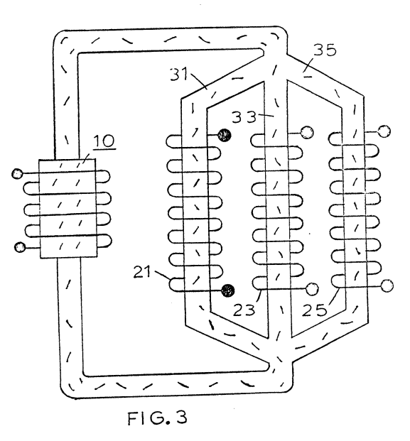
Figure (3)
Figure (3)
How it is written
- (3) 2×
Drawings 1
-
The output 22 of the secondary transformer 20 is a high voltage/current output. · Electrical Particle Generator
Where it is named · 2
Electrical Particle Generator 2×
-
Figure 3 is an illustration similar to Figure 2 but adaptable to 3 phase.
-
It can be appreciated that the system of Figures 1 and 2 utilizing a single closed loop will provide a single phase output in the secondary winding. With particular reference to Figure 3 there is illustrated a closed loop system having three parallel non-magnetic tubes 31, 33, and 35. On each tube or pipe there is a respective secondary winding 21, 23, and 25.