Figure (4)
Figure (4)
How it is written
- (4) 3×
Drawings 1
-
Beside the passage · Electrical Particle Generator
On this figure 1
Where it is named · 3
Electrical Particle Generator 3×
-
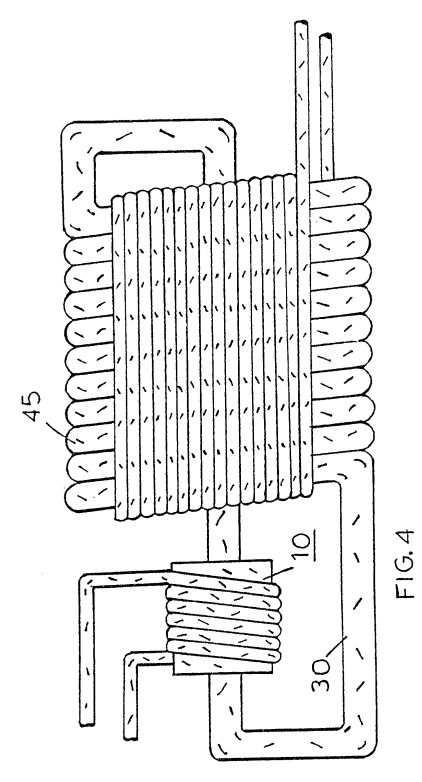
Figure 4 is a first alternative arrangement in a preferred illustration of the invention.
-
The electrical power generator illustrated in Figure 4 is in electrical operation identical to. that in Figures 1 and 2. The physical configuration of the arrangement is adapted to be utilized in a high moisture environment. An insulating coating 45 completely covers the pipe 30, as well as all electrical windings.
-
In Figure 4 there is illustrated that increasing the number of coils'with a given size winding the voltage/current output is increased. The physical configuration illustrated is such that the vertical aspects as well as the horizontal aspect are utilized. In this way a large diameter pipe can be used with a substantial number of turns of heavy-gauge high-current wire.