(14)
Air
Also written intake air
Where it is first named
The output of mixing chamber 40, as described relative to Figure 1 is fed via line 9 to a gas mixture system 42. In this instance the intake air 14 may be in a carburetor arrangement with an intake adjustment 55 that adjusts the plate 42 opening. The gas mixture 15 is fad into the carburetor by nozzle 11 and mixed with the air 14.
How it is written
- (air 14) 2×
- (intake air 14) 1×
Drawings 2
-
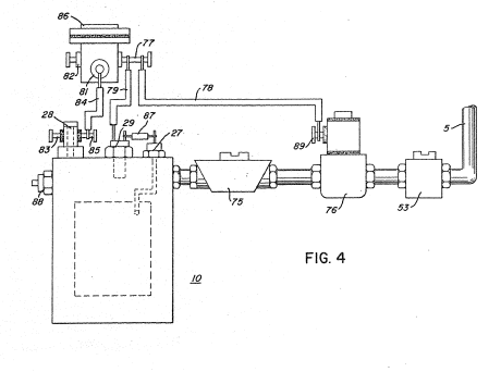
Figure 4 is a block schematic illustration of a gas control system for retrofitting existing automobiles to a combustion system of the present invention; and · Hydrogen Air & Non-Combustible Gas Mixing Combustion System
-
The figure it sits on · Hydrogen Air & Non-Combustible Gas Mixing Combustion System
Where it is named · 3
Hydrogen Air & Non-Combustible Gas Mixing Combustion System 3×
-
intake air (intake air 14)
The output of mixing chamber 40, as described relative to Figure 1 is fed via line 9 to a gas mixture system 42. In this instance the intake air 14 may be in a carburetor arrangement with an intake adjustment 55 that adjusts the plate 42 opening. The gas mixture 15 is fad into the carburetor by nozzle 11 and mixed with the air 14.
-
air (air 14)
The output of mixing chamber 40, as described relative to Figure 1 is fed via line 9 to a gas mixture system 42. In this instance the intake air 14 may be in a carburetor arrangement with an intake adjustment 55 that adjusts the plate 42 opening. The gas mixture 15 is fad into the carburetor by nozzle 11 and mixed with the air 14.
-
air (air 14)
… The gas mixture combines with air 14 as it enters the cone area 65 and the combined mixture combustible gas 15 is directed by the cone 65 to the dispersing chamber 66. …