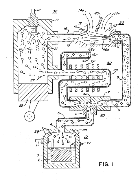
Figure (1)
Figure (1)
How it is written
- (1) 11×
Drawings 2
-
Captioned as this figure · Hydrogen Air & Non-Combustible Gas Mixing Combustion System
-
Beside the passage · Hydrogen Air & Non-Combustible Gas Mixing Combustion System
On this figure 13
- 10 Generator
- 14 Air
- 15 Mixture Combustible Gas
- 18 Spark Plug
- 22 Exhaust Gases
- 42 Gas Mixture System
- 55 Intake Adjustment
- 59 Combustion
- 63 Cone
- 64 Non-Combustible Gases
- 67 Ports
- 74 Outlet
- 95 Alternator
Where it is named · 11
Hydrogen Air & Non-Combustible Gas Mixing Combustion System 11×
-
Figure 1 is a schematic, cross-sectional illustration of the present invention in its preferred embodiment;
-
Figure 2 is a block schematic illustration of the preferred embodiment of Figure 1;
-
Referring particularly to Figure 1 the complete overall combustion system is illustrated together with a mechanical drive piston.
-
With particular reference to Figure 1, the hydrogen source 10 is the hydrogen generator disclosed and described in my aforementioned Application Serial No. …
-
The apparatus of Figure 2 comprises much the same system as Figure 1. In this embodiment the components are depicted more explicitly in their structural relationship in an alternate arrangement. Basically, the system is operable in the same manner as that in Figure 1, i.e. it utilizes a mixture of combustible (hydrogen) gas and non-combustible gases (exhaust).
-
The apparatus of Figure 2 comprises much the same system as Figure 1. In this embodiment the components are depicted more explicitly in their structural relationship in an alternate arrangement. Basically, the system is operable in the same manner as that in Figure 1, i.e. it utilizes a mixture of combustible (hydrogen) gas and non-combustible gases (exhaust).
-
The output of mixing chamber 40, as described relative to Figure 1 is fed via line 9 to a gas mixture system 42. In this instance the intake air 14 may be in a carburetor arrangement with an intake adjustment 55 that adjusts the plate 42 opening. The gas mixture 15 is fad into the carburetor by nozzle 11 and mixed with the air 14.
-
… The mixture designated gas 56, ejected from ports 67a xxx 67n of the dispersing chamber 66, is ignited by the pilot light and thereby causing combustion 59 of the mainstream gases, As the non-combustible gases 64 (exhaust gases 22 of Figure 1) rise upwardly in the cylinder 61, of the combustion chamber 60, the cone 63 captures a portion of the non-combustible gases 64. …
-
… The captured exhaust gas is returned via pipe line 68 and outlet 74 to the combustion process as set in Figure 1 or expelled for other purposes. …
-
… In operation, the process mixture is ignited much in the same manner as in Figure 1. …
-
… That is, again referring to Figure 1, the electrical voltage applied to contact 27 is in the closed loop with the alternator/mechanical drive of Figure 5 In this way, the voltage requirements for the hydrogen generator are drastically r …