(40)
Chamber
Where it is first named
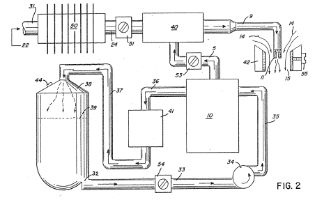
A portion of these exhaust gases 22 are fed via pipe line 24 to the gas mixing chamber 40 providing the non-combustible gases for mixing with the generated hydrogen gas.
How it is written
- (chamber 40) 4×
Drawings 1
-
Beside the passage · Hydrogen Air & Non-Combustible Gas Mixing Combustion System
Where it is named · 4
Hydrogen Air & Non-Combustible Gas Mixing Combustion System 4×
-
chamber (chamber 40)
A portion of these exhaust gases 22 are fed via pipe line 24 to the gas mixing chamber 40 providing the non-combustible gases for mixing with the generated hydrogen gas.
-
chamber (chamber 40)
The pipe line 24 passes through cooling chamber 50 far cooling of the gases therein. The cooling chamber 50 also functions as a spark arrestor to eliminate the possibility of gas ignition inside the mixing chamber 40. The excess non-combustible gases are exhausted via outlet 49, to be expelled into the atmosphere.
-
chamber (chamber 40)
The outlet 5 on the generator 10 receives the combustible (hydrogen)and non-combustible gases generated thereby and directs the same to the mixing chamber 40. The flow of the hydrogen gas is, of course, critical; therefore, there is incorporated in line 5 a gas Flow valve 53 to adjust the hydrogen gas flow.
-
chamber (chamber 40)
Gas regulator valve 75 is utilized to reduce the pressure level inside the hydrogen generator 10. The pressure differential hydrogen gas output to gas mixing chamber 40 is, for example, 30 lbs. …