Figure (1)
Figure (1)
How it is written
- (1) 14×
Drawings 1
-
Beside the passage · Resonant Cavity Hydrogen Generator That Operates with a Pulsed Voltage Electrical Potential
On this figure 5
Where it is named · 14
Resonant Cavity Hydrogen Generator That Operates with a Pulsed Voltage Electrical Potential 14×
-
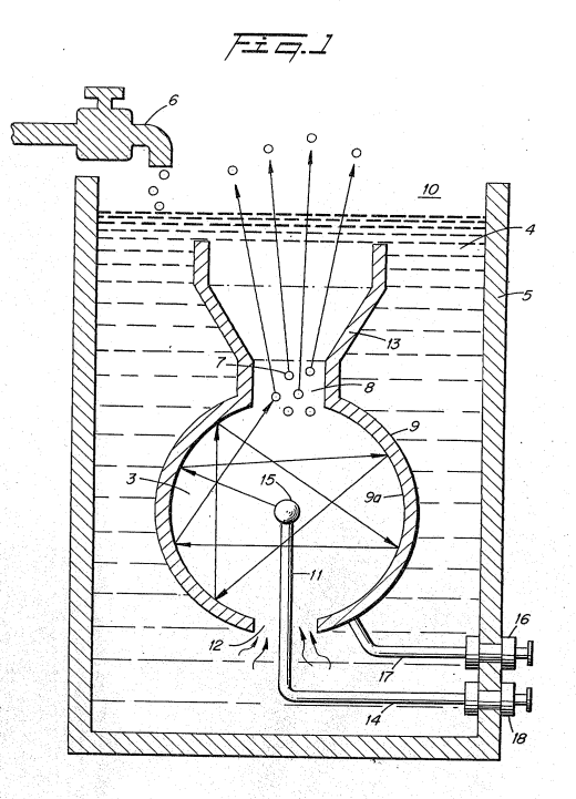
Figure 1 is a schematic illustration of the structure of the present invention in its most simplified arrangement.
-
Figures 2, 2A, and 2B, are a series of waveforms illustrating the pulse rate of the direct current to' match the resonant frequency of the structure of Figure 1.
-
Figure 3 is a schematic illustration of the utilization of the structure of Figure 1.
-
Figure 4 is a first alternative structure to that shown in Figure 1.
-
Figure 5 is another alternative structure to that shown in Figure 1.
-
Figure 6 is another alternative structure to that shown in Figure 1.
-
Figure 7 and 7A are an array of exciters, such as shown in Figure 1, in a preferred embodiment.
-
Reference is now made to the several figures depicting the preferred embodiment of the present invention. Referring to Fig. 1. there is illustrated a device 10 which includes a vessel 5 having therein an outer shell 9 and an inner element 15. The shell 9 has a gas expulsion opening 8 in its uppermost region, and a gas guide 13 flared out from the opening 8.
-
With specific reference again to Figure 1, the distance from the outer surface of the central element 15 to the inner surface 9a of the outer spherical element 9 will be at some wavelength correlated to the molecular motion of travel. …
-
In the sphere of Figure 1, the directions that the water molecules may travel from the inner sphere 15 to the surface 9a of the other sphere 9 is of an infinite number. …
-
Returning to Figure 1, an opening @ is provided in the uppermost portion of the outer sphere 9 of the resonant cavity 3 structure. …
-
The structure of Figure 1 is that of a sphere 9 with another sphere 15 positioned therein. The spacing between the outer surface of the inner sphere 15 to the inner wall 9a of sphere 9 provides a resonant cavity to a given frequency of the physical force of the direct current voltage. Other resonant cavities may be utilized in other arrangements.
-
The structure of Figure 3 is substantially identical in operation to that of Figure 1. …
-
Referring now to Figures 7 and 7A, the structure of Figure 1 is in an array of resonant cavities 50a to 50n. Specifically, the housing 51 having water 52 therein includes the array of exciters, having a positive potential applied to its central element 53a to 53n, via terminal 64 and a negative potential to the outer element 55a to 55n.